"Lofting" originally meant drawing full-sized patterns for ship frames. It was so called because it was often done in large, lightly-constructed mezzanines or lofts above the factory floor; the people who did this kind of layout work, originally using flexible rulers called splines held in place by weights called ducks, were called loftsmen.
There are many ways to generate systematically varying families of curves on a flat surface. One such family that lends itself to both graphical and mathematical production is that of the conic sections. Conics were often used for ship lofting, and were widely adopted for aircraft design in the 20th century. Although the mathematics of conics has been well understood since classical times, it was a North American Aviation mathematician, Roy Liming, who was responsible for putting aircraft lofting on a purely mathematical footing in the late 1930s. Supposedly the beautiful Mustang was the first airplane to be entirely lofted in this way. Liming believed (incorrectly) that the Mustang's superlative performance was due to the precision of its surface contours.
Around 1980, with the assistance of Rob King, who put the necessary equations into a usable form for me, I began writing BASIC software that generated airplane lines using mathematically derived conics. At first, it generated only cross-sections. The original program, running, or rather strolling, on a Radio Shack TRS-80, was called BLOFTER, for "Bulkhead Lofter." I didn’t have a printer -- they weren't being given away yet then -- and to preserve my results I would photograph the screen.
BLOFTER became the three-dimensional FLOFT ("Fuselage Loft"), written in C, and FLOFT eventually merged with a separate wing lofting program, WLOFT, to become LOFTSMAN, written in a mixture of C and C++. All of the lines of Melmoth 2 were generated mathematically by FLOFT and LOFTSMAN.
The lines of the original Melmoth were generated graphically. This was easily done because the airplane was skinned with metal, which does not lend itself to compound curves. The longitudinal lines were therefore mostly straight, and so it was necessary to define only a few cross-sections and then to interpolate the ones between them.
Melmoth 2, on the other hand, is a composite airplane, and like most composite airplanes it tries to make the most of the medium by clothing itself, or at least its fuselage, entirely in compound curves. It's very difficult to define the shape of a compound-curved surface otherwise than by lofting -- a good definition of shape is needed for designing the interior structural components -- and so LOFTSMAN, or some other program like it, is a prerequisite for designing free-form composite airplanes.
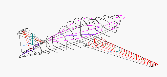
Melmoth 2's fuselage is lofted in several pieces: a main body, canopy, and a cowling scoop. The program combines them into a single shape. In addition to the shapes of cross-sections, canted sections, intersections, and longitudinal components like longerons, it calculates surface area, volume, and, for purposes of weight estimation, the centroids of the surface area and volume of the entire fuselage or of any segment of it. Here is a composite of some of the lines used or generated by LOFTSMAN, including wing geometry with spar locations (orange) and fuselage intersection, master longitudinal lines for the fuselage components (black and violet), vertical cross-sections at intervals of 20 inches (black), and the line of intersection (blue) between the canopy and the body. Circles with crosses represent the aerodynamic centroids of the wing, vertical fin, and horizontal stabilizer.
One of the virtues of a mathematical loft is that it is necessarily fair. You can change a longitudinal contour, and the entire fuselage reshapes itself to accommodate the new line without losing its overall smoothness. And, because you know the exact location of the surface at any point, it's easy to plan the installation of interior structure, mechanisms, equipment and furnishings.
When I needed to build tooling for the wing, the program plotted chordwise wing contours at 10-inch intervals. These were glued to particle board, cut out, and secured to a tabletop in order to make a series of cradles for the female molds in which the wing skins, four of them, were laid up. As would be expected, given the inherent precision of the loft, the top and bottom skins of each wing fitted together perfectly. Not only does the program calculate total wing tank volume, but it also does so for partial fuel loads and for any aircraft attitude. I was therefore quickly able to determine the amount of usable fuel in various flight attitudes, and to predict the fuel quantities that would correspond to various positions of the sender floats, of which there are two in each wing, one in the root rib and one at mid-span.
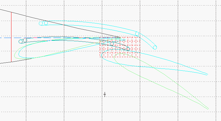
LOFTSMAN provides a procedure for designing flaps to fit in an existing wing, and also for designing the tracks and actuators required to make the flaps follow a desired path. Since Melmoth 2 has a large Fowler flap that translates aft all the way to the trailing edge of the wing before deflecting 30 degrees, the track geometry was relatively critical. Here is the roller track design screen. To define a roller track, you first set several points along the flap travel; you then move the rollers around with the mouse, and the slot shapes constantly change to match the desired travel.
If you're curious to learn more about conic lofting, you can download a free demo version of LOFTSMAN from the AeroLogic website at www.aerologic.com, together with documentation. I sell the program for $200 in a version that does lofting only; the version advertised on the website, which also performs meshing for computational fluid dynamics models, is more expensive.

