NACA inlet sizing for the TSIO-360
(It is important to note that the following discussion concerns sizing of an engine induction air inlet. Flush inlets perform best when feeding into a suction, which an engine supplies; not so well against a level or rising pressure gradient.)
The following was my thinking in arriving in a 1.15 x 4" throat for the engine air inlet.
The assumed airflow, based on the displacement, the maximum rpm, and the maximum manifold pressure (41 in Hg or 1.37 atm) is about 24,000 cu ft/hr. One way to arrive at this figure is to multiply the engine speed (2,800 rpm) by half the displacement (because the cylinders fire on every other rev) and then by the ratio of the assumed manifold pressure (41) to the naturally-aspirated manifold pressure at sea level (about 29). An internal Lycoming evaluation of their competitor's engine reports an airflow requirement of 16,250 cu ft/hr (1,300 lb/hr) for the naturally aspirated engine, which is logical considering that volumetric efficiency is less than unity.
The maximum flow translates into 11,500 cu in/sec for takeoff power at sea level. To get the required size of the inlet, you have to decide on a ratio between the flight speed and the speed of flow in the inlet; this is called the velocity ratio or the mass flow ratio. For a NACA inlet, the optimum ratio is 0.7 -- that is, the duct velocity should be seven tenths of the flight speed -- but ratios can range from 0.5 up to 1.5 without a huge loss of efficiency. NACA R.M. No. A8B16 , p. 34, shows ram recovery (also called pressure recovery) greater than 90% for mass flow ratios from 0.6 to 1.5 at 0.3 Mach -- very optimistic, but what the heck. For low-level takeoff and climb, in any case, ample turbo boost is available and so maximum ram recovery is not needed.
It's worth noting that in the absence of a suitably gradual diffuser -- that is, an expanding duct -- to slow down the airflow before it reaches the air filter, ram recovery is going to fall far short of theoretical values anyway. Nevertheless, its seems desirable to properly match the duct size to the flow rate.
Supposing 2,800 rpm, a climbing TAS of 140 mph or 2,500 in/sec, and a velocity ratio of 1.0, an inlet area of 4.6 sq in would be required at sea level. At the critical altitude of 18,000 feet, more cubic inches of ambient air will be required to achieve 41 in Hg in the intake manifold, and the required duct size goes up to 8.1 sq. in.
For cruise, the air and fuel flows are reduced, and you need a different method of computing the air requirement. Knowing that about 14.9 pounds of air are required to combust one pound of fuel at peak EGT and that air weighs 0.08 lb/cu ft at sea level, you can calculate that to combust a gallon of fuel, which weighs six pounds, requires about 90 pounds, or 1.94 million cubic inches, of air. For convenience, since duct sizing is generally expressed in terms of inches and flow rates in cubic inches per second, this can be expressed as 540 cu in/sec of air per gallon per hour of fuel consumption. You have to remember, however, that this number is based on sea level air density, and has to be corrected for higher altitudes. It also has to be corrected for leaner mixtures; a 75 deg. F lean-of-peak mixture uses about 20% more air than a peak EGT mixture.
Cruising at 12,000 ft. at a TAS of 210 mph or 3,700 in/sec, a fuel flow of 10 gph with a stoichiometric mixture implies an airflow rate about half of the takeoff/climb maximum, and an inlet section of only 2.2 sq. in, again assuming a velocity ratio of 1.0. Cruising at 18,000 ft requires 21% more area than at 12,000, other things being equal.
The problem now is to see whether or not there is a throat area that provides a mass flow ratio between .5 and 1.5 for all flight cases, and that puts the ratio near optimum (0.7) at some commonly used flight condition, such as 60-70% power at 10,000-12,000 feet.
Applying the 1.5 mass flow ratio to the max rpm climb at 18,000 feet, the throat area drops from 8.1 to 5.4 sq in. Applying the 0.6 ratio to the 10 gph cruise, 210-mph cruise case at 12,000 ft., the area rises from 2.2 to 3.67 sq in. Air flow is directly proportional to fuel flow, and so an 8.5 gph cruise would require 85% of this area, or 3.12 sq in. On the other hand, changing the mass flow ratio from .6 to .8 would reduce the required area to 2.34 sq in.
Cruising at 10 gph at 18,000 ft and a mass ratio of 0.6 requires 4.44 sq in.
Cruising at 9 gph at 10,000 ft and a mass ratio of 0.8 requires 2.3 sq in.
And so on.
It appears that it is not possible to optimize the inlet for both maximum performance at the critical altitude and for the normal cruise points. It seems reasonable to sacrifice maximum climbing performance at the critical altitude, but even so it is still not possible to perfectly reconcile maximum power and economy cruising performance at non-oxygen altitudes. In the end, I decided on an area of 4.6 square inches. Various NACA reports recommend that the rectangular throat of the inlet have a width/depth ratio between 3:1 and 5:1; hence my final dimensions of 1.15 by 4 inches.
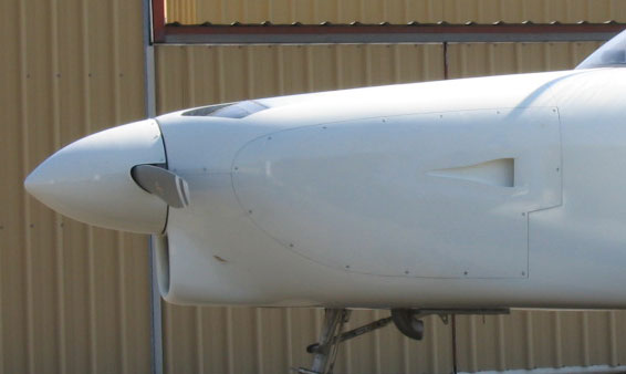
The shapes of the scoop walls and of the airfoil-shaped "lip" or outer surface of the scoop are defined in NACA reports, several of which are listed below. Many commercially available molded scoops are much shorter than the NACA pattern, and the lip shape is often ignored altogether. The lips of properly formed NACA inlets have substantial thickness; mine are about 0.4 in thick at a location one inch aft of the leading edge of the lip. The floor of the throat is therefore 1.55 in below the external contour of the cowling, and, since an angle of seven degrees is recommended for the ramp, the overall length of the ramp ahead of the entrance is about 12 inches.
-------------------------------------------------------------
Here is a bibliography of reports that I was able to download from the Internet. The first one does not relate directly to NACA scoops as such, but provides a broad, if rather opaque, introduction to the general topic of air inlet and outlet performance.
NACA Report No. 713, Internal Flow Systems for Aircraft; Rogallo. 1940.
NACA Advance Confidential Report No. 5120, An Experimental Investigation of NACA Submerged-Duct Entrances. Frick et al. 1945.
NACA Research Memorandum No. A8B16. An Experimental Investigation of NACA Submerged Inlets at High Subsonic Speeds. I -- Inlets Forward of the Wing Leading Edge. Hall and Barclay. 1948.
NACA Research Memorandum No. A8F21. An Experimental Investigation at Large Scale of Several Configurations of an NACA Submerged Air Intake. Martin and Holzhauser. 1948.
NACA Research Memorandum No. A5OE02. Pressure-distribution and Ram-recovery Characteristics of NACA Submerged Inlets at High Subsonic Speeds. Frank. 1950.