The wing of the first airplane I designed, Melmoth, had a constant chord of four feet. It consisted basically of two four-by-four foot panels on each side of the fuselage, four feet being a standard width for aluminum sheet. The center portion, about 12 feet in span, had no dihedral; the outer panels had eight degrees. There was no washout. The wing geometry was taken, essentially unchanged except for the airfoil, from the Thorp T-18, in large part because John Thorp was a friend, allowed me to use the metal-forming equipment in his Sun Valley, California shop, and answered my questions during morning palavers over coffee and bear claws at a place called Mr. C's. I figured that what had worked for him would work for me.
That I copied a wing design from another airplane shows what an arbitrary and irrational process airplane design can be (and often is). That the airplane was successful in spite of the wing's not really being optimized, or even appropriate, for its mission shows that rationality can sometimes be dispensed with.
Melmoth had a very long cruising range, more than 3,000 sm, which was achieved not by the conventional avenue of a high lift-drag ratio, but by the mere provision of a lot of internal tankage. Tip tanks holding 35 gallons each supplemented wing tanks holding 42 each. Melmoth flew from Cold Bay, Alaska to Sapporo, Japan, 2,650 sm, in 1976 with two souls and lots of baggage aboard, and landed with 23 gallons remaining. The flight took 14 hours and 45 minutes.
Around 1979 I discarded the tip tanks and replaced the outer wing panels with ones of eight-foot length, increasing the span to 28 feet. The result was undiminished range and speed and increased rate of climb and performance at high altitude. (Since I had also recently installed a turbocharger, high-altitude performance had begun to matter to me more than it had before.) The span increase was structurally possible because the main spar was originally designed for acrobatic load factors.
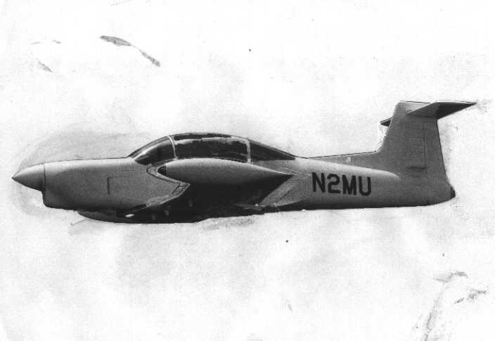
I began building a new composite fuselage for Melmoth 1 in 1981, because my companion Nancy and I were about to have a baby and it seemed as if we were going to need a larger airplane. I also craved a new project, and I was then laboring under the delusion that composite airplanes were easier and quicker to build than metal ones. I could of course merely have stretched the existing airplane by inserting a plug in the fuselage, and I did do some design work on that idea. Here's what it looked like in a doctored photograph:
But I wanted to experience composite construction, and so I decided to build a completely new fuselage instead. Making a fuselage from scratch had the collateral advantage (I thought) that I would not have to ground the airplane for as long as I would if I were cutting the metal fuselage apart.
Maybe, on the other hand, I should have just cut the old one apart after all, because then, perhaps, it would not have been holding short of the right runway at Orange County Airport on the afternoon of July 16, 1982, just in time to be hit and chopped to pieces by an out-of-control Cessna attempting to land on the left.
The destruction of Melmoth 1 meant that I now needed to design a new wing to go with the new fuselage and empennage that were already under construction.
By the time I designed the wing for what was now Melmoth 2, the fact that wingspan per se is an asset to an airplane had finally sunk in. In fact, although we usually talk about aspect ratio -- the ratio of the span to the average chord -- as the essential attribute of highly efficient airplanes like sailplanes, it's really absolute span that most strongly affects efficiency. (Efficiency here means getting the most pound-miles and the greatest rate of climb for the least power.) Drag does too, of course, and since sheer surface area produces drag, it's desirable to have the smallest possible wing area combined with the largest possible span -- in other words, a high aspect ratio. But it is span, pure span, that affects the price in drag that an airplane pays to produce lift, and that price is about half of the total drag around the airplane's speed for best rate of climb and best range (about 40% above the clean stalling speed).
To investigate the effects of span on performance I used a computer program based on one given me in the late 1970s by Burt Rutan. For the airplane I wanted to build, which was basically Melmoth all over again but with four seats, it turned out that by the time the span approached 40 feet the improvement to be expected from adding yet more had become negligibly small. In fact, at a certain point additional span has a negative impact because it increases both weight and wetted area. As far as I could tell, at around 37 feet the wing was about as efficient as it was going to get. I settled on a span of 35 feet, based on the width of the hangars at the airport where I expected to be based.
To give you a sense of the diminishing returns to be had from increasing span, here is a plot of wingspan against the calculated variation of L/D ratio, maximum rate of climb, and fuel flow required to maintain a true airspeed of 200 mph, for Melmoth 2 at 17,500 feet. (These numbers do not take into account any drag or weight penalty for increasing span.) You can see that fuel flow and rate of climb don’t improve by much once the span is 35 feet or more.
It may seem paradoxical that the L/D ratio continues to increase, but fuel flow does not diminish at the same rate. The principal reason is that the fuel flow figures are taken not at the best L/D speed but at a much higher speed, where the impact of increasing span is smaller.
Having determined a span, I now had to fix upon a planform -- the shape of the wing as seen from above. I did not want to increase the wing area beyond Melmoth's, which had varied from a minimum of about 87 square feet (fair tips, no tanks), through 94 (tip tanks), up to 112 (extended outer panels). I was prepared for the wing loading to rise to 28 lb/sq ft at high operating weights, which would be encountered only very seldom. For comparison, most four-seat general aviation airplanes have wing areas of about 160-180 square feet and maximum wing loadings of around 20 lb/sq ft.
There were several design criteria. One was undiminished range, which meant that either the fuel capacity had to stay in the vicinity of 140-150 gallons or the efficiency had to increase sufficiently to compensate for a lesser capacity. Another was sufficient section depth near the root to accommodate the retracted landing gear without any protrusion. I was planning to use the main gear struts and the retraction linkage from a Piper Cherokee, although they would have to be modified considerably. The section depth requirement meant that the root airfoil would have to be thick; I set 18% as an arbitrary maximum. Even so, the Cherokee half-forks and 600x6 tires were too thick -- about 10 inches -- to fit inside the wing, and I decided to enclose them beneath the seats; but the swing of the retraction linkage still demanded a certain section depth within the wing itself.
In order to be able to transport the dismantled airplane more or less conveniently, I decided to build an 8-foot-wide stub section into the fuselage. The landing gear would be mounted in that section, so that the airplane would stand on its gear even with the wings removed. The gear track would be about seven feet -- rather narrow, but not unacceptably so. I have had no reason to regret this decision.
After experimenting with various configurations I decided on a double-tapered planform with a kink in the leading edge two feet out from the side of the fuselage. This arrangement allowed the top of the inboard panel -- the part that would be built integral with the fuselage -- to be straight and horizontal -- a convenience, since the seats would rest on top of this section.
The root chord is 52.3 inches, and the chord at BL48.000 (buttock line 48 -- 48 inches from the plane of symmetry) is 44 inches. The tip chord was originally intended to be 20 inches. There was some risk that the taper ratio would be excessive, because the aerodynamic effectiveness of an airfoil is affected by its size, and by the time you get down to 20-inch chords you start to encounter a noticeable loss of maximum lift. The tip airfoil was optimized for good lift at low speeds, and the stall, though not friendly, is not vicious either.
The airfoils were designed by John Roncz, who was doing airfoil design work for Burt Rutan at the time and whom I had come to know through my friendship with Rutan. The foils are of the laminar flow variety, the root section being slightly reflexed in order to harmonize with the fuselage flow field. The section at BL48 is called SODA (for Stamp Out Drag Airfoil) and the 13% thick tip section is POP (Peter's Outboard Profile). Roncz brings a whimsical touch to his airfoil naming; he once responded to a request for an airfoil with an unusual amount of thickness far aft with OSPITE -- Olympic Swimming Pool In Trailing Edge. The sections he designed for M2 are similar to those used on Rutan's Catbird, an airplane in some ways akin to mine.
Roncz was of the opinion that designers tend to use too much twist. Having no clear opinion of my own on this subject I deferred to his, and provided the wing with comparatively little twist. The root incidence is 2.00 degrees; at BL48.000 the incidence is 0.5 degrees, and it is -0.83 degrees at the tip. The purpose of twist is to delay the stall of the outer panels and maintain aileron effectiveness, so that the airplane does not roll off suddenly at the stall. Often, however, twist fails to produce a sufficiently tame stall, and sharp leading-edge "stall strips" are added to trigger the stall inboard. This seems to be the case with my wing, but I have not yet turned my attention to the problem of getting nice stalling characteristics.
The dihedral angle of 3.17 degrees was something of a stab in the dark, related more to the geometry of the tapered spar than to any sort of refined aerodynamic calculations. Although I found support for it in a chart in Perkins & Hage, a classic aerodynamic text, most people seemed to think it was not enough, and they were right. Anticipating that an adjustment to the dihedral effect might be required, I had originally built the wings with a span of 400 inches rather than the intended 420; in the spring of 2004 I added tapered tips, swept 45 degrees and turned up 30 degrees, which increased the span to 430 inches and remedied the deficiency of dihedral effect. The chord at the extreme tip is now six inches and the airfoil there is an uncambered NACA 0009. Some doubts were voiced about the suitability of an uncambered airfoil for the wingtip, but it seemed to me that since the lift coefficient at the tip is zero anyway, it didn't make much difference what airfoil section was used, or whether it had camber or not.
Excepting the portion of the centersection aft of the main spar where the landing gear is mounted, the wing is entirely an integral fuel tank from 5% of chord to 70%. Its volume is about 71 gallons on each side, of which three are unusable when the airplane is in a 15-degree nose-up attitude. The spar, located at 31% of chord, has no sweep. The aspect ratio is 12.8.
Geometric aspect ratio is one thing, effective aspect ratio another. The ratio between them is called e, or "Oswald's efficiency factor." An untwisted elliptical wing free of Reynolds number effects should have an e of 1.0, but 0.8 is a more typical value. The losses are due to deviations from the ideal elliptical lift distribution, and in the case of Melmoth 2 are exaggerated by the large size of the fuselage in relation to the wing. There are various ways of calculating span efficiency. A simple texbook formula makes Melmoth 2's quite low -- about 0.65 or less. Analyzed alone, however, the wing has an e of about 1.0. At first I accepted this discouraging result, but flight experience showed persistently better performance at low speed than such a low value of e would suggest. Panel code analysis of the complete airplane (but without the wingtip extensions) using CMARC yields values, varying with angle of attack, between 0.8 and 1.0.
The minimal dihedral, although aerodynamically acceptable once the upturned tips were added, is a potential cause of problems with fuel distribution. If the airplane is fueled on sloping ground, or if one wing is filled disproportionately, so that its oleo compresses much more than the other's, fuel may run outboard, further exaggerating the imbalance. To fully fuel the airplane, it would be necessary to add fuel by 10- or 15-gallon increments, moving back and forth until both tanks are full.
Prior to the installation of flaps and ailerons, each wing, excluding again the centersection, weighed 52 pounds. The skin is a sandwich, carbon on the inside and glass on the outside, with a quarter-inch thick core of two-pound Divinycel foam. Carbon sandwich ribs are spaced about two feet apart. The single main spar, a channel with forward-facing caps, is entirely carbon. The stub spar that is built into the fuselage is a carbon I-beam. The spar splice between the outboard panel and the fuselage stub consists of a 24-inch overlap secured by three 3/8-inch close-tolerance bolts at the inboard end and four at the outboard end. The bolts are in steel bushings and the faying surfaces have flush aluminum surface plates laminated into the spars.