Burt Rutan and Mike Melvill came down to the big hangar at Whiteman Airport, where I then rented space, in August, 1981 and laid up the inner skins of the top and bottom halves of the aft fuselage as I watched. This was my introduction to wet layup; I took over from there. The tail cone, from the fin post bulkhead to the trailing edge of the wing, was made by heating 1/2-inch thick foam sheets in a homemade convection oven to soften them, and then bending them and gluing them into place in a fixture consisting of particle-board cradles. After the inner skins had been laid up by Burt and Mike, I added frames, then joined the top and bottom with glass tapes along the inside of the seam. Finally, I sanded the outer surface of the foam to give it continuous longitudinal contours and added the outer skin in my garage during the winter of 1981-82.
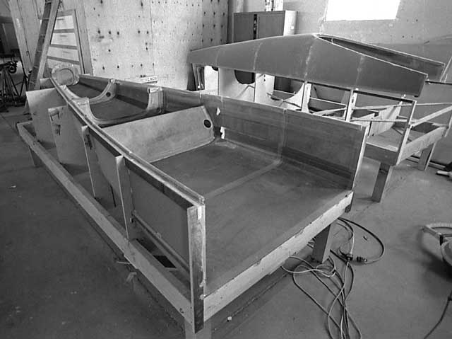
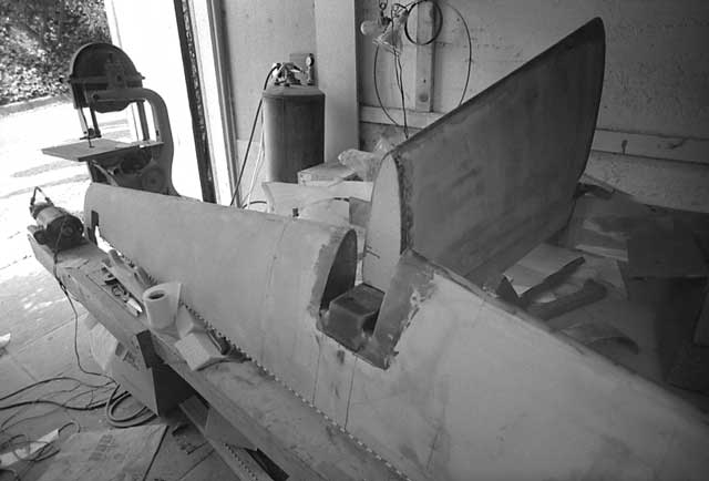
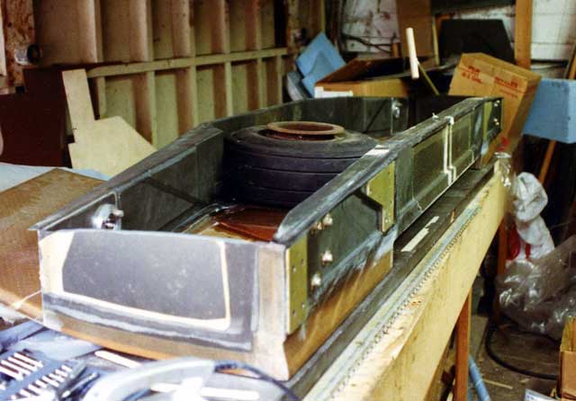
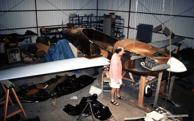
In this picture and the next one, the frames have been installed and the top half has been lifted out of its fixture and set down upright on top of it. The slanted bulkhed in the lower half is the footrest for the back seats. At this point, I still imagined that the project would be finished in another year or two.
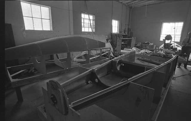
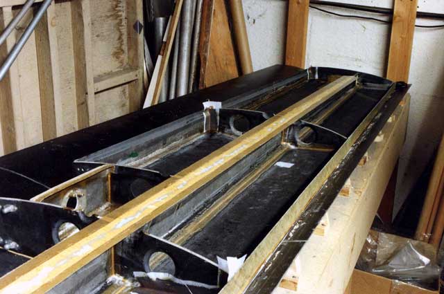
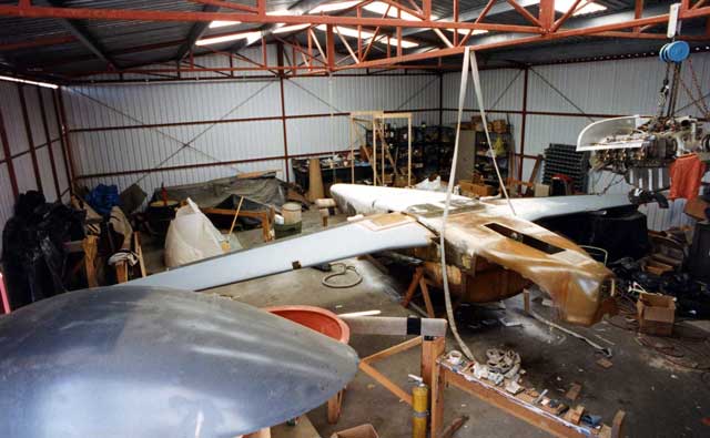
Same scene, different angle. Graphite tapes visible in the lower corners of the bottom half-shell were supposed to serve as longerons, but despite their high elastic modulus it's unlikely that they carry much load since there is so much fiberglass sandwich that is farther from the flexural axis. The spacing of bulkheads was a matter of guesswork; I did not have access to sufficiently sophisticated methods of composite analysis to make rational decisions. The structure is heavier than a comparable metal one would have been. The weight of the sandwich skin and frames, which consist of two plies of 6-oz bidirectional glass cloth over a Klegecel core, is about equivalent to that of .036 aluminum. An aluminum tail cone of equivalent strength and stiffness would probably use .025 material.
The tie-wearing figure on the right is the late Jack Smith, an old friend of mine and a remarkable fellow who could guess the size, weight or cost of anything and be right 95% of the time.
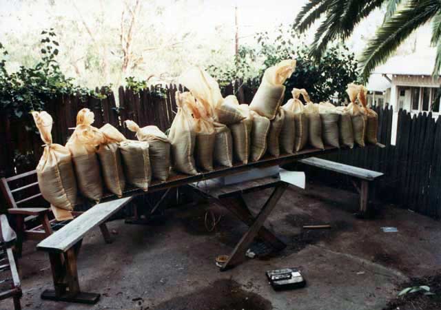
In 1983, prior to joining the vertical and horizontal stabilizers, I static-tested the horizontal stabilizer, and my homemade picnic table, with 900 pounds of sandbags. When I picked up the first one I thought there was no way the tail could hold them all, but it did, deflecting about 1.5 inches over a semi-span of 56 inches. The limit load is actually 1,000 pounds; I don't know why I didn't carry the test right up to the limit load. Probably afraid of breaking something, though there would still, even at 1,000 pounds, have been, at least theoretically, a 50% margin of safety.
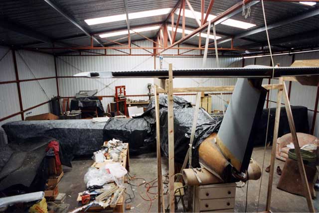
The T-tail, mated. The horizontal uses a continuous piano hinge for sealing. Both the horizontal and the vertical have box spars of carbon fiber, bonded web-to-web and taped along all the mating edges with carbon cloth. A fair joint between the leading edges, added later, would complete the torsional connection. Once this rather massive assembly was done -- it weighed 50 pounds -- I had to get it out of the garage in order to have room for other work. A kindly neighbor, Lornie Frauman, consented to hang it up in his garage on my assurance that it would not be there long. It remained for years.
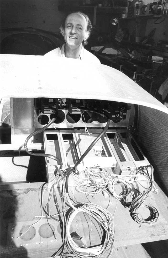
Among the parts of the first Melmoth that survived the accident were the instruments and radios. The radios were Collins MicroLine that I had acquired in 1975. I laid them out horizontally to provide them with ample cooling. The shelf on which the wire looms are resting is a foam-cored box beam, about ten inches wide and an inch thick, that extends from side to side of the fuselage and is bonded to the upper longerons. The engine mount box bolts to its front edge; the bolt holes and the aluminum reinforcements embedded in the lamination are visible.
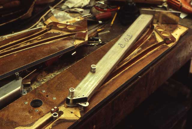
From time to time I would stray into some useless and very complicated detail. These are the two frames that support the boarding steps, which slide in and out on rollers in tracks that resemble flap tracks. At the outer ends are phenolic blocks that take the bearing loads from the weight of a person on the step. The steps were supposed to be electrically actuated and I have all the hardware for doing it, but I have never gotten around to making them work. I pull them out by hand to help people get aboard, and then push them back in. Friction keeps them in place.
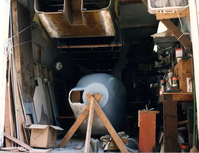
I used the cowling from the original Melmoth as a starting point for a new one. I split it top and bottom and right and left to adapt it to the shape of the new firewall, which was close to that of Melmoth 1. After I had matched it to the fuselage, I hoisted the fuselage into the rafters and continued finish work on the cowl. I made a two-part female mold and then laid up the cowling in four parts. The sides were done first, with the Camloc rings laminated in place. They were then screwed into the mold through the rings and the bottom and top laminated. Each part overlapped the previous ones so that in the end they fit together perfectly. The bottom cowl became an integral part of the fuselage, providing lateral support to the engine mount.
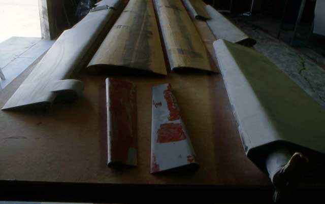
I built the wings in female molds made of "laminate", a common construction material used for kitchen countertops. The laminate was glued to particle board cradles at 10-inch intervals. Steel or aluminum would have been better; the laminate formed slight waves that had to be filled and smoothed later. But at least it was cheap and easy to handle. I had to repeat the process four times, destroying each mold after one use, because there was not room in the 10x17-foot garage for more than one. I built the spar and ribs into the bottom skin, and provided channels in the top skin that I filled with microballoon-thickened epoxy when mating bottom to top. The wing skin is a sandwich consisting of an inner carbon layer .016" thick, a 1/4-inch Divinycel core, and an outer layer of two plies of unidirectional glass oriented 45-45. The glass provides little strength, but it protects and stabilizes the inner carbon skin. The spars and ribs are of carbon-Divinycel construction. For the spar caps, I laminated unidirectional carbon cloth into sheets about .080" thick, then sawed them into strips an inch wide and built the caps up by interleaving them with successive layers of carbon shear web. I had the unidirectional strips tested; they took about 70 ksi in compression. I had used 60 ksi as an ultimate allowable -- about the same as 2024 aluminum.
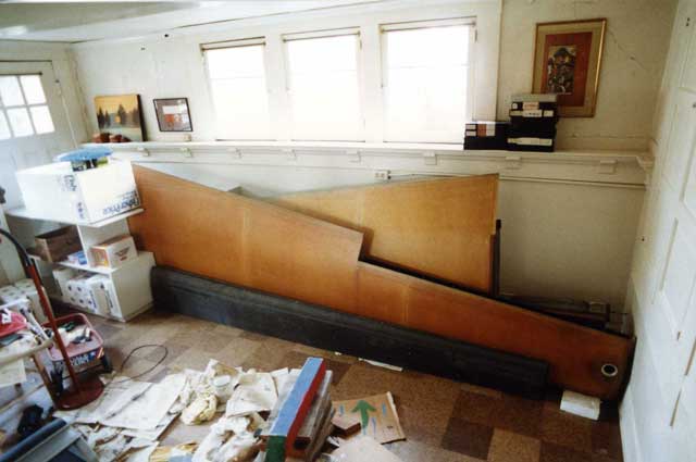
When the wings were assembled I stashed them and the Fowler flaps, which were made in the same molds, in the basement. It was now the mid 1980s. The reason the basement has windows is that our house is on the side of a hill.
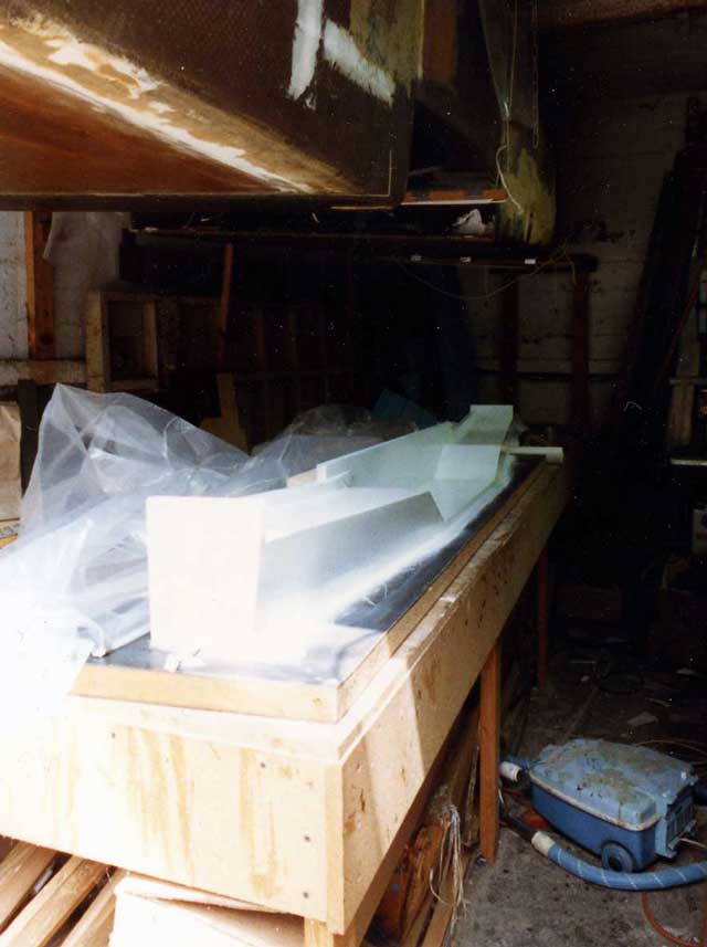
One of the more complex structural elements was the rear spar for the wing centersection. It needed to be joggled to accommodate the wheels, which retract under the seats, but its upper cap also needed to take compressive loads associated with the main landing gear, which mounts against the rear spar. I began with a wooden mold eight feet long.
After laying up one carbon skin and the upper spar cap, I added foam cores to stiffen the shear webs. All laminations were room-temperature-cured, but vacuum bagged to reduce weight and make sure everything conformed perfectly to the molds.
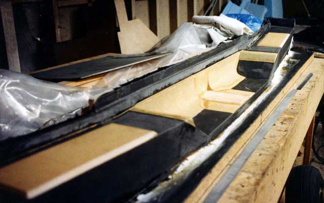
After completing the rear spar, I built up the centersection box, which became an integral part of the fuselage. The wing panel spars overlap the box by 24 inches and bolt to it through the green aluminum plates with a total of seven 3/8-inch close-tolerance bolts on each wing. In order to minimize the intrusion of the centersection into the cabin, its main spar had to be several inches shallower than the spars of the wing panels; the light-brown surfaces are the difference between the two spar depths.
The overlapping spar joints entail a weight penalty of several pounds, but composites do not take concentrated loads well and so attachment points need to be widely spaced when large bending moments are involved. The workspace I had available made it impractical to build the wing in one piece, and to do so would also have sacrificed the convenience of having the airplane still standing on its landing gear when the wings are removed.
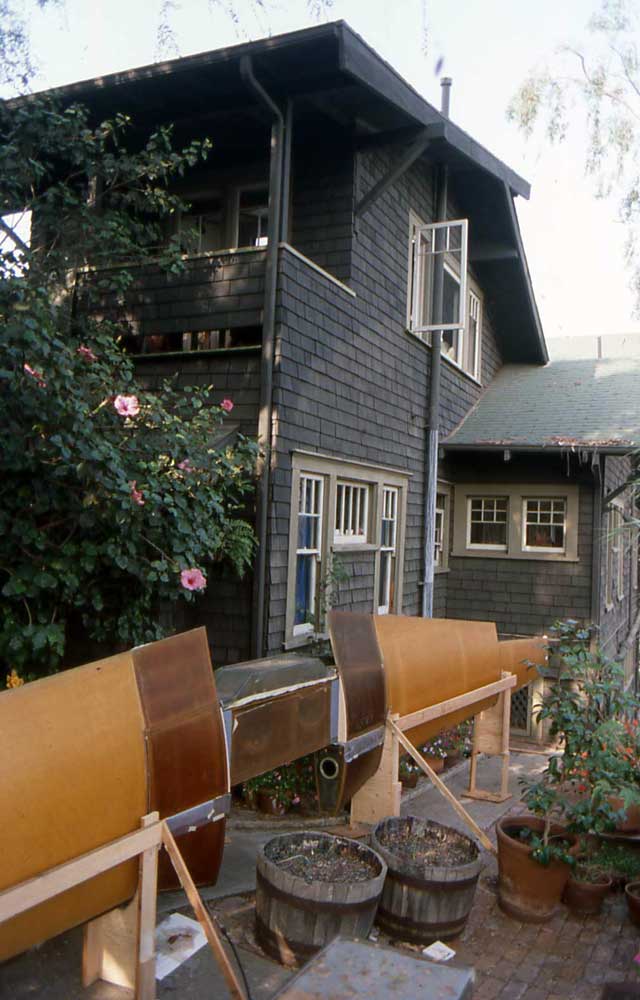
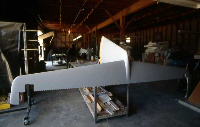
Now it was possible to assemble the entire wing and check the alignment of parts, which turned out to be okay. At this point the wing was more than 33 feet long -- its final span is about 36 feet -- and the only place to put it together was in the front patio of our house. The round hole in the inboard leading-edge rib is an inspection and access port. Unfortunately, it is usable only when the wing is removed from the airplane.
The blurred object above the gravity-heater vent is clearly a UFO.
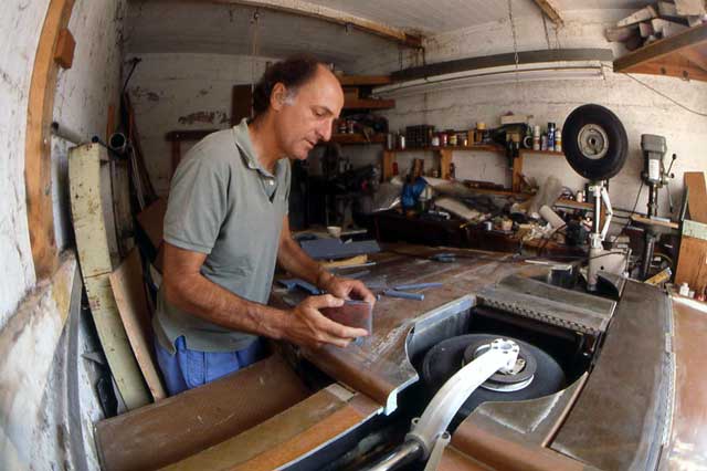
I could now bond the wing centersection into the fuselage, close up the gaps, install the main landing gear and make the wheel well doors. The centersection spans eight feet, my workbench was 24 inches wide, and the garage is 10 feet and 3/4 inch wide, allowing 3/8-inch clearance at each end of the box. To get where I am standing, I had to crawl under the wing on my hands and knees and slither up into the narrow space. The fuselage, from aft bulkhead to firewall, is 17 feet long -- the length of the garage, which must have been built for a Model T. The fisheye lens exaggerates its size considerably. By the early 1990s lack of space had slowed progress almost to a halt.
The dark panel just ahead of the wheel wells is the airbrake.
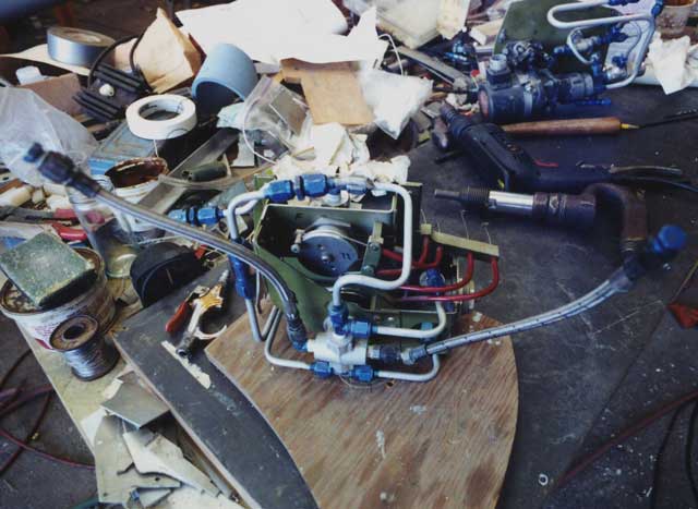
Of course, not everything was composites. There were also systems to take care of, principally the fuel system, which incorporates filters, an aux pump, and a timer and motor for automatically switching tanks, and the hydraulic system, which operates the landing gear, flaps, and airbrake. In over-reaction against the sprawling hydraulic system of Melmoth 1, which used a lot of heavy solenoid valves, I decided to make this one simple and compact and to control it mechanically. This assembly holds three valves that are actuated from the control panel through cable loops. It mounts in the space below the front seat occupants' knees and above the airbrake, and can be removed for service. Of course, the complexity of its connections, both hydraulic and mechanical, is a great deterrent to removing it. Fortunately, in almost fourteen years of flying it has not yet required service.
Other views of this modern sculpture are here, here and here.
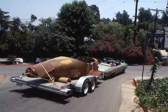
I finally came into possession of a hangar at Whiteman Airport and moved the airplane out there in the summer of 1992. I had the '68 Malibu since 1977, when I bought it for $50. It had 450,000 miles when I gave it to my son Nick, who loved it more than I did, for his 32nd birthday.
Note the trunnion, used to rotate the fuselage, still attached to the rearmost bulkhead.
I flipped the airplane over to smooth and prime the underside. While it was in this position, a friend, Jack Smith, brought over a friend of his to show him the plane. Assuming that this stranger was familiar with things aeronautical, I gave him all the details. At this time the main gear doors were not in place, and so there were two holes where they should have been. My guest, after patiently listening to me, asked, "Where do the other two people sit?"
The gray and red objects in left foreground are the male and female canopy molds.
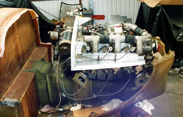
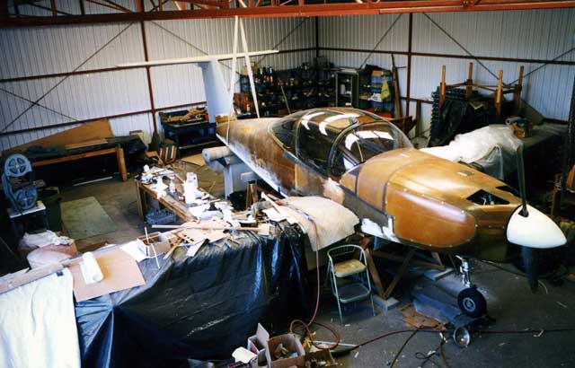
With the engine in place, I had to make a new set of baffles to accommodate updraft cooling. The firewall is a lightweight sandwich of ceramic cloth in a bismaleimide matrix with a Nomex honeycomb core and carbon rear surface, courtesy of a friend at Hexcel Corporation. It is supposed to be able to pass the FAA firewall test, which consists of blasting the firewall with a big 2,000-degree flame for 15 minutes.
Since room-temperature-cured structural composiites do not thrive at the temperatures that prevail inside a cowling, the engine mount is built up of .050 aluminum. It was rather pleasant to revisit sheet metal and rivets, old friends from the first Melmoth. The reason for using a box structure to support the engine is that since the high-pressure side of the cooling circuit is below the engine, the nosewheel well has to be isolated from the cowling. With downdraft cooling, the nosewheel can simply retract into the cowling.
Incidentally, the canopy window in the background is a memento from Melmoth 1. It was the pilot's side gull-wing door, and bears the scars of the Cessna wing that missed my head by a few inches.
After an unsuccessful attempt to vacuum-form a canopy in a female mold, the plastics guy stretched parts over a male plug. I laminated and vacuum-bagged the canopy frames over the windows in the female mold, so that the outer surface is more or less perfectly smooth. The windows are held in the frames by adhesive, without mechanical fasteners. The canopy is optically quite good except in one place -- right in front of the pilot.
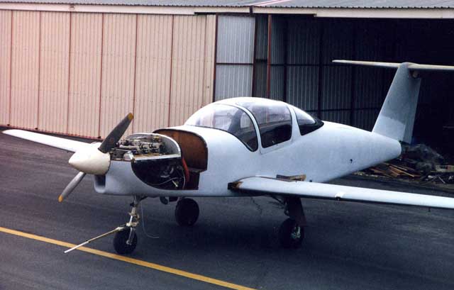
In 2000 I was able to run the engine and taxi around the airport. That it still took another year and a half to get ready to fly puzzles even me.
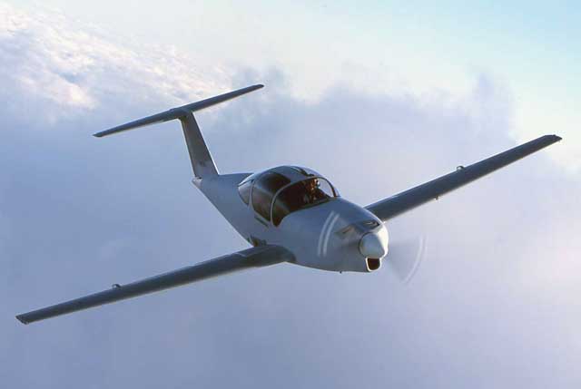
The big canopy weighs about 50 pounds and is not as aerodynamically clean as a faired turtledeck might be, but the view in all directions is worth it.