[March 19, 2026]
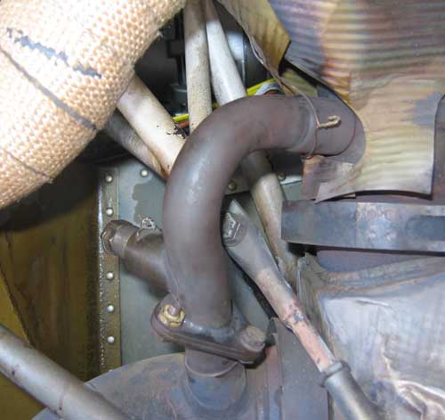
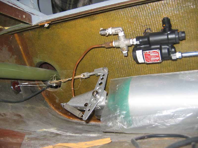
The replacement of the fuel drains turned out to be a protracted nightmare which I am reluctant to revisit, even in memory. Suffice it to say that I finally managed to get one of the new ballcock drains installed on the left wing, only to find that interferences with existing plumbing in the right wing would make it impossible to install one there without making revisions too onerous to contemplate. So now I have one ballcock drain that will never drip because of trapped crud, but that requires opening the airbrake and getting under the airplane to operate, and one conventional quick drain that can be operated by a person crouching beside the airplane but whose tiny O-ring will leak at the slightest provocation.[December 12, 2025]
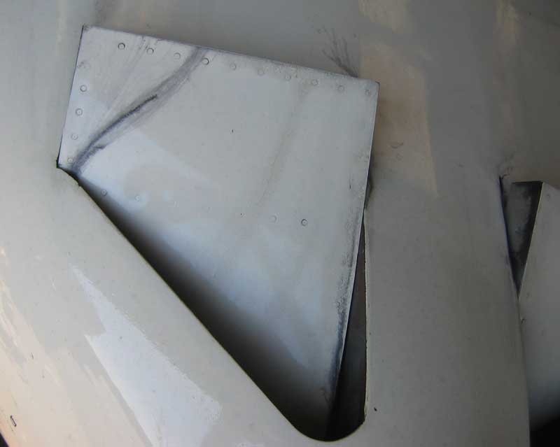
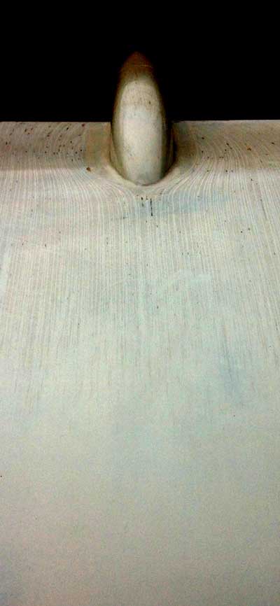
For the past ten years or so I've been aware of several very fine cracks in the upper surface of the horizontal stabilizer, where you had to go pretty far up a ladder just to see them. I marked the ends of the cracks with pencil and observed that they grew at a rate of at most 1/8 of an inch a year. It was very likely that these were filler cracks, since they were not in a particularly highly stressed area. I finally decided to make sure, and sanded away the area in question, down to the lamination. Embarrassingly, the filler was about 1/8 of an inch thick at that particular location. It's not that bad everywhere. The underlying skin was fine, so I just had to fill up the hole I had made, which was about 3 by 4 inches. This is done with a mixture of epoxy and plastic microballoons, which resemble flour but are much lighter, each microscopic particle being -- if not broken -- an empty bubble. You could fill a page, in a small font, with detailed instructions on how to fill a hole, from how to mix the epoxy-microballoon filler so that it is as dry as possible but not too dry, to how to wet the bottom and edges of the hole with a very thin smear of epoxy and press the filler into the edges so that tiny gaps don't appear around the perimeter when you sand the filler, and how to mound the filler slightly above the surface contour and then sand it down after it cures. The reason you do it that way is that, as with Bondo, it's desirable to do the filling in a single pass and not to keep filling low spots with additional layers. Multiple rounds of filler risk producing regions of slightly different hardness that sand slightly differently. At any rate, I managed to fill and smooth the wound pretty satisfactorily. I then found a can of "ivory" spray paint whose plastic cap, which is supposed to show the color of the paint, exactly matched the paint on the airplane. Unfortunately, it did not exactly match the paint in the can, but no matter, since 1) areas painted with the actual original paint, but years later, are even less similar and 2) nobody brings a ladder to look at my airplane anyway.[October 13, 2025]
I was mid-sentence in the process of replying to an email from Dan Fritz, who had made some suggestions regarding the sump drain question, when it dawned on me that if I was going to have to open the airbrake to get access to the sump drains, the drain valves didn't have to be crowded into the tight gap between the wing and the edge of the airbrake; they could make use of the ample space above the brake itself. Weird how the mind works, or rather doesn't.[October 9, 2025]
I recorded a couple of speed points today. The air was extremely smooth, and there seemed to be no vertical movement in the air mass; but one can't be sure. I was at 10,500 feet, density altitude 12,000. At 23/2300, lean of peak, I saw 174 knots true (145 kias) at 8.3-8.4 gph, or about 57% power. My generally reliable computer simulation says that I should have been using 9.8 gph at that speed. Seldom have I seen it so far off. I then set the power at 21.5/1900, and got 152 ktas (126 kias) at 7.1 gph (45%), which is exactly in line with the simulation. I can't account for the divergence; the simulation is normally in good agreement with experience. Incidentally, the engine is pleasantly smooth and quiet at 1,900 rpm; I would use that setting more often, but it coincides with some blade resonances that I should probably avoid.
[October 2, 2025]
[September 24, 2025]
I got to the airport for the first time since returning from the east coast a week ago. It was unexpectedly moving to see the plane, which I had washed just before leaving, gleaming marble-white in the hangar's filtered light. For a couple of minutes I just stood and gazed at it, like a person lingering over a just-rediscovered photo of an old love. I recall a lovely sentence of George Eliot, from Adam Bede: "It was that moment in summer when the sound of the scythe being whetted makes us cast more lingering looks at the flower-sprinkled tresses of the meadows." In this case, the scythe is being whetted for me. Flying has decided to run my two columns alternately rather both in each issue. This deprives me of about a third of my already exiguous income, and makes my ownership of an airplane even less defensible than it was before.[August 19, 2025]
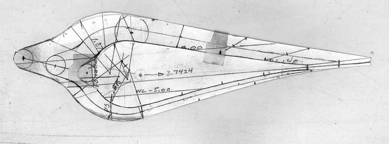
Back in January, 2007 I installed a fairing around the exhaust pipe. Its intended efect was to preserve a more or less coherent boundary layer between the exhaust stream and the fuselage, thereby preventing staining and leakage of exhaust into the cabin. For some reason, I failed to take the precaution of using my analysis software to determine the angle of flow in the vicinity of the exhaust. As exhaust stain built up on the underside of the fuselage, it was apparent that the fairing was misaligned. Now, after ignoring this annoying imperfection for 18 years, I finally got around to re-orienting the fairing, which turns out to need to be at a (surprisingly large) 10-degree angle to the airplane centerline (trailing edge outward). Until I've flown a few times, it won't be clear whether this modificatoin did any good.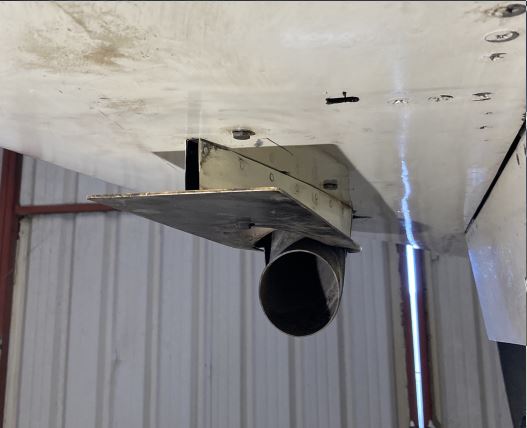
[August 13, 2025]
The other day I was flying and noted down the fuel flow, density altitude and indicated airspeed. I later checked the numbers against my computer simulation and was glad to see that they matched precisely. That the simulation is a good predictor of the performance of the airplane would have no particular significance, unless one were planning a flight over a very long distance. I am not planning such a flight, except in imagination; but suppose, for example, I wanted to fly to Hawaii. Then the ability to simulate the performance of the airplane at various weights and power settings would be quite helpful. The shortest distance is Oakland to Hilo, around 2,330 statute miles; Los Angeles to Honolulu is 2,555. With 140 gallons of fuel usable in level flight, and able to cruise at 180 mph at 9 gph even at gross weight -- fuel flow drops as weight diminishes -- the plane can obviously make the Oakland-Hilo trip with good reserves. It could even make it in under 12 hours, but the cushion gets a bit scanty, with 19 spare gallons for taxi, climb and reserve. What is noteworthy is that it's not necessary to fly anywhere near the airplane's best-range speed, which would not only make for an agonizingly long and slow trip, but would in fact use more fuel than a higher speed. The reason is that the specific fuel consumption rises considerably at very low power settings, and the best L/D speed, 103 imph at 2,100 pounds and 119 at 2,800, occurs at between 35 and 39 percent power. What you're really interested in, if you want to go the longest possible distance, is not the best L/D speed but the speed for best specific range, that is, the most miles per gallon. That occurs, for example, at between 138 and 155 mph TAS at 12,500 feet. Note that L/D speed is an IAS, invariant with altitude, whereas specific range speed is a TAS and therefore increases with altitude. So for the quickest trip you would fly at the highest altitude you could; at 20,000 feet you could cruise at 200 mph and arrive with more than 30 gallons in reserve, but an empty oxygen tank.[July 5, 2025]
I modified the lidar gear warning software to make the beep rate of the alarm signal inversely proportional to height; this is supposed to convey a sense of urgency as I descend gear-up toward the runway wondering what that beeping noise I'm hearing is all about.[October 16, 2024]
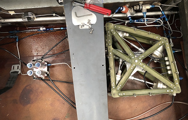
My casual prediction that at the rate I was going the last couple of hose replacements should take me through the fall proved to be correct. I finally finished that project today. The final step was the most complicated, and involved removing the inboard flap actuator cylinders and replacing the hydraulic lines coming from the far aft ends, which were simply lengths of nylon tubing secured to the cylinder with tie wraps, with hard tubing terminating in an AN bulkhead fitting. The bulkhead fitting is secured to a flange that protrudes from the side of the cylinder at a right angle, and is bonded to it with silicone caulk to allow the cylinder to expand under pressure. Now the tie wraps pass under the hydraulic tubing, to keep it from rubbing against the cylinders. Whether this whole operation was worthwhile is questionable, but at least it looks better than it used to, and will certainly not be subject to connections popping loose under intense solar heating of the hydraulic fluid, as happened twice with the nylon plumbing.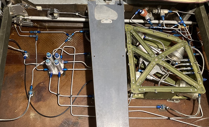
[June 20, 2024]
After being away most of the month of May and half of June, I finally finished the installation of the lidar gear warning system and flew the plane for the first time in 3 months. It started instantly and seemed none the worse for the long period of idleness. I found that I had by now forgotten which color wire I needed to disconnect to override the gear position signal and test the lidar portion of the system, but that can wait. Ironically, returning to Whiteman, when I was a mile or so out, I ran the landing checklist and found that I had failed to put the gear down. I attribute that oversight to my approaching fast straight in, so as not to inconvenience the airplane turning base behind me. I slowed from 130 to 100 knots rapidly with the airbrake, then put down half flaps. This was a deviation from my normal practice, which is to put the gear down before the flaps. Perhaps I unconsciously consider the flaps a confirmation that the gear is already down. If so, I had better make it my unvarying practice to do gear first, then flaps.[April 13, 2024]
Yesterday I began installing the gear warning system. The first step was to track down the wires going to the up and down lights on the panel, and I discovered that my recollection of the system, which I installed several years ago, was all wrong. I had mixed up the microswitch that enables the landing lights to operate (they are on a gear leg, and so don't light when the gear is retracted), with the switches -- it turns out there are two -- that trigger the gear position lights. So I actually have a "gear down" signal available, not just a "gear up" signal, and the ambiguity of a null "gear up" signal, which could mean gear down or gear in transit, is removed.[April 11, 2024]
I finally assembled the lidar rangefinder gear warning system, but have not yet installed it. It consists of a lidar rangefinder, an Arduino computer and a relay. When the rangefinder tells the computer that the distance to something below the airplane is less than 30 feet, the computer energizes the relay. The relay in turn completes a circuit that gets power from the "gear is up" branch of the gear position microswitch. If the gear is not up, that circuit is not energized and so nothing happens. If the gear is up, the circuit is hot and an alarm sounds. There is an LED that lights whenever the rangefinder says the plane is below 30 feet agl, whether or not the gear is down, and a press-to-test button to check, from time to time, whether the beeper is working.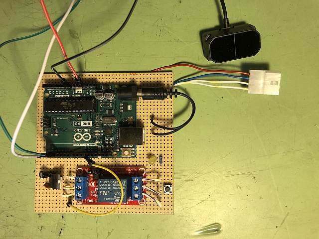
[February 13, 2024]
I have replaced all but two of the nylon lines with proper aluminum and a small fortune in AN fittings, and am now having a hard time bleeding the system. I realize now that certain components could have been better designed to avoid trapping bubbles; unfortunately it is unlikely that I will ever get to apply that knowledge. In the meanwhile I have also begun working on a landing gear warning system using a lidar sensor to trigger an alarm when the airplane is less than, say, 30 feet from the surface and the landing gear is not down. I have never done much with electronics before, but with the help of Peter Lert and YouTube, anything is possible.[December 15, 2023]
Having rehearsed the procedure in my mind a great many times, I set out to replace just one of the nylon hoses in the flap synchronizer with an armored hose with AN flare fittings, etc. It turned out to go more smoothly than I had expected, and in a couple of hours I did all four of the main feed/vent connections. Luckily my visualizations had forewarned me to partly lower the flap before making the change; that way the air that got into the system would be flushed back to the reservoir when the flap was retracted. I will not be able to attempt the next step until after Christmas, the time between now and then being consecrated to making cookies for our annual Christmas party which, after two years of Covid and one of Nancy's broken hip, is resuming its otherwise uninterruped 35-year run. The next step will be to connect the master cylinder outlets to the bubble catchers, four little towers that are supposed to collect any air that finds its way into the lines between the master and slave cylinders. I anticipate that stage being simpler than the first, which required partly dismantling the synchronizer frame; all of the fittings for the second phase are accessible from outside the frame.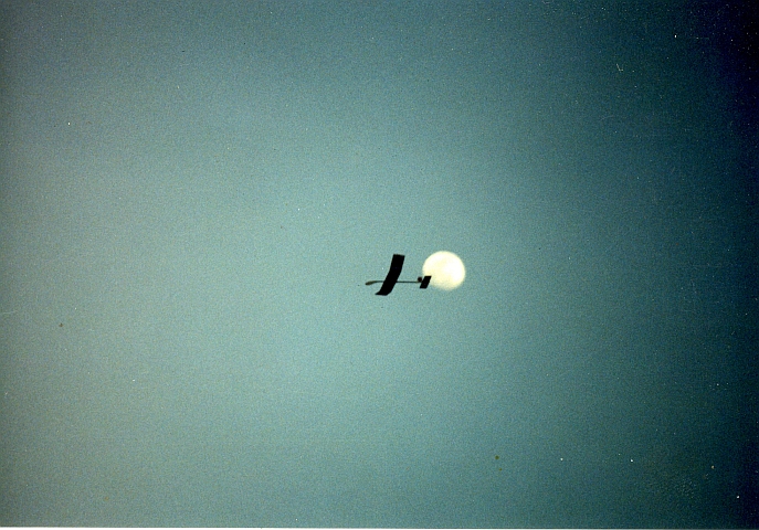
[September 28, 2023]
After some floundering around I learned that you can buy the plastic breakable link for a Rapco vacuum pump. It came today. The chief mechanic at Able Air told me that once one of these things has failed you might as well get a new pump, because it's friction in the pump that caused it to fail. However, I can't discern any friction in the pump, so I'm going to give it a try. The worst that can happen is that the pump fails again, which won't matter, since I no longer fly IFR. In the course of removing the pump I discovered that a steel bracket, whose intended purpose was to stabilize the throttle body, had fatigued and broken. The break could not be seen, I have no idea when it failed; I installed it in 2014.[September 6, 2023]
A while ago I received a card inviting me to join the octogenarian pilots' association. I have not yet acted upon it; the reality takes time to sink in.[March 5, 2023]
The trim system is pleasantly smooth now, demonstrating that lubricants are not all they're cracked up to be. I checked compressions; three were 80/80, none lower than 77/80, surprisingly good for an engine that qualifies, on time flown alone, as run out. Spectroscopic oil analysis after changing the oil found no ill omens. The radios -- Collins MicroLine dating from the 1970s -- are getting a bit weak; I may need to stop using earplugs under my headset. The airplane's main problem now is hydraulic leaks. I keep toying with the possibiity of replacing all of the nylon lines I now use with a combination of hard aluminum lines and a bunch of short Aeroquip hoses to accommodate cylinder movement. As I mentioned last June, it's a project that would cost quite a bit of money and might yield little or no improvement, since the leaks may be principally in the cylinder seals.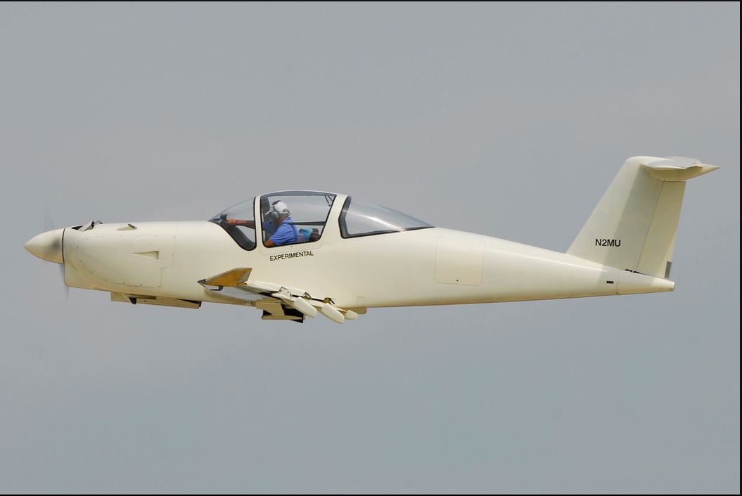
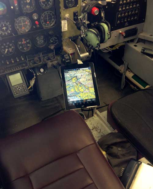
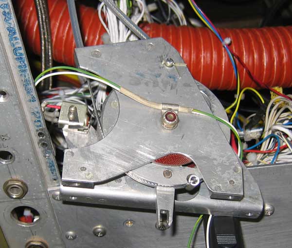
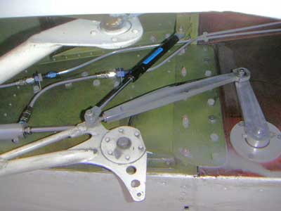
The
reason for
the peculiar position of my right arm is that the gear is in transit.
The gear handle must be held in the "up" (or "down") position
while the gear is cycling; it is returned to the center detent once the
gear is up or down. The flaps work the same way. Both flap and gear
handles are connected by cables to closed-center hydraulic
valves, and directly actuate microswitches to energize the
hydraulic
pump.
[January 17, 2023]
Having gotten the trim system back into shape, I noticed that there seemed to be some friction in the elevator circuit, so I pulled out the hinge pins and cleaned and dry-lubed them, one with Molykote and the other, when the Molykote spray can clogged, with some stuff from Home Depot called Blaster. The elevator is still not exactly frictionless, but at least the friction is more or less constant throughout its travel, not variable as it was before.[January 3, 2023]
Nancy being at last sufficiently mobile that I can leave her alone in the house, I was at the airport yesterday and today trying to track down the cause of the extreme stiffness, indeed virtual inoperability, of the pitch trim. After exonerating the trim jackscrew, whch I originally assumed was the culprit, I finally homed in on the sprocket that converts the linear movement of the trim cables, via a length of bicycle chain, to rotary motion in the jackscrew. Apparently, long ago, in an effort to gild the lily (or, as the bard actually put it, to gild refinèd gold and paint the lily), I greased the bushing that supports the sprocket. In the course of (much) time the grease dried out, and now the sprocket would barely turn. I was kicking myself for the inaccessibility of the assembly, and had already taken a bunch of stuff apart (including removing the rudder), when I realized that all I really needed to do was take out the elevator bellcrank and I could remove the sprocket and its supporting bushing easily. I cleaned up the bushing, put the assembly back together dry -- aluminum is a perfectly good low-speed bearing surface for a steel shaft, even without lubricant -- and re-installed it. Now I just have to undo all the unnecessary disassembly of the surrounding structure. Actually, it has not been a complete waste of time; I was able to inspect a lot of hidden pieces and confirm that everything is holding up. I was impressed by the ingenuity with which I (not I who am writing, but an I of many years ago, practically a stranger to me now) had modified and cobbled together various pieces of a much longer linear actuator to make the current trim system. It really isn't bad at all.[December 7, 2022]
I flew today for the first time since September 22. My long absence from the upper air was not voluntary. Nancy and I spent the month of October in Ojai, with only occasion brief returns to Los Angeles, helping our son manage his two kids while their mother was doing a 30-day yoga program in Bali. No sooner did we get back than Nancy fell and broke her hip. She was in the hospital for three weeks, two of them in rehab getting physical therapy. I was with her most of the time. Now we're back home at last, and a day finally arrived when our daughter Lily, who came out here from New York between jobs to help, could hang out with Nancy while I went flying. Too much information, I admit. Anyway, the plane still flies, although now that colder weather (actually, standard atmosphere) is here the grease that I foolishly put on the pitch trim jackscrew has stiffened up and made the trim practically inoperable. I have to take the assembly apart, clean the screw and nut, and lubricate them either with dry graphite or not at all.[September 22, 2022]
I did a speed check today at 10,500 ft. The density altitude was 13,000. Speed seems to be a little off the expected numbers; at 25/2300, 25 LOP with a fuel burn of 9.9 gph, I got a true airspeed of 184 knots, versus an expected 189; or, to put it differently, versus an expected 9.5 gph. My engine is around TBO, and while I believe even an old engine will develop rated power, I'm not sure it will develop rated sfc. Since I use a curve-fitted sfc model to determine power for purposes of performance calculation, if the actual sfc is higher than I am assuming then the engine is developing less power at a given fuel flow, and so speed would be below the predicted value.[August 2, 2022]
Sure enough, the problem with the landing/taxi light was a broken ground wire, which I found and fixed. I seem to have suffered an unusual number (two) of broken ground wires lately; the reason is probably related to the fact that a composite airplane does not have the convenience of airframe ground, and so uses a great many more ground conductors than a metal airframe would. In many instances I used shielded conductors with the shield as the ground return, but not in the case of the landing light.[August 1, 2022]
Today I revised the wiring connections for the switch panel, and in so doing I found the broken ground wire that was the reason for the anticollision lights not working. Now they work, and, collaterally, that particular patch of wiring is a little better organized than it was before. Tomorrow I will tackle the problem of the inoperative landing lights. It will probably turn out to be something similar. I always imagine electrical gremlins to be more devious and subtle than they really are.[July 29, 2022]
The persistent refusal of the so-called strobes (they are actually halogen lamps) to work continues to baffle me. I have tried to troubleshoot the problem armed with a digital multimeter and almost zero understanding of electricity, and gotten about as far as I deserve to. The wiring behind the panel is not so well organized and labeled as one would wish, to put it mildly. Generally, my wiring resembles that of a Delhi slum. I decided to do some housekeeping there on the assumption that I would stumble on a solution to the strobe problem in the process. Actually, what I have stumbled on so far is that the landing/taxi light is not working either. They have nothing in common other than a 15-pin Molex connector that I've decided is too crowded with wires, so I'm dividing its occupants between two smaller connectors, one for the nav/panel/landing lights and another for the strobes. The flasher circuit was designed by the late Paul Lipps, who also made me the little board that operates it. It incorporates some ingenuity to increase bulb life; in the words of a caption, "This unusual dual-bulb flasher eliminates high inrush currents by using one bulb's heated filament to limit the starting current for the other bulb." This refinement may be superfluous, since the small halogen bulbs I use are practically given away and I don't fly at night anyway.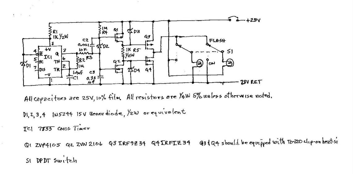
[May 5, 2022]
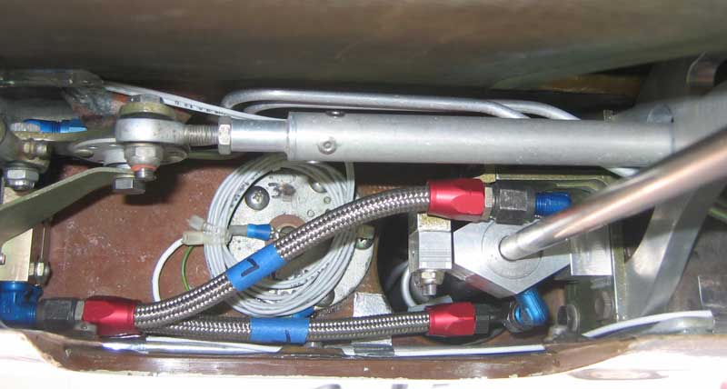
Cinco de Mayo! And with it --- well, nothing, actually. Yesterday I flew around for an hour, going, as usual, nowhere. I noticed that the left main strut was a little low, which is surprising, since with warmed weather you'd think it would get a little higher. It's been years since I've added air to the struts; they hold air well. I dipsticked the fuel, and found that it perfectly matched the totalizer. This seems always to be the case, although I never set the totalizer by the dipstick value, only by the gallons added. The totalizer is an old Alcor that Mike Melvill gave me; the company, whose employees are all younger than the totalizer, now denies any knowledge of its existence. The so-called strobes still aren't working, I don't know why, and the Lowrance GPS is increasingly demented, but who isn't?After I finished that chore, I was lying under the plane trying to figure out where a hydraulic fluid drip was coming from and to decide whether it was even serious enough to bother tracking down. I suspect the airbrake actuator; its O-rings are about 20 years old. My main gear actuator is also a possible culprit. It came from an Aztec, I think, and I can't remember now whether I overhauled it before I installed it, which was maybe 25 years ago. If either of those is the source of the leak, I won't be surprised. Maybe both are. But I couldn't summon the energy to pull either actuator, so I just lay there looking up into the well where all the hydraulics are and thinking, "God, I did this?"
At some point recently my "strobes" -- they're really blinking halogen lights -- stopped working. I have tried to track the A+ and ground wires through the maze behind the panel to find the problem; so far no luck. On a more cheerful note, I got a comm radio (Collins MicroLine VHF-251) on eBay for $150 to replace the one that quit. It works reasonably well -- well enough for a backup.
[January 3, 2022]
My anxiety about the apparent inaccessibility of my oil screens turned out to be a case of hypochondria by proxy. Though I could not recall having inspected the oil screens -- there are two, a suction screen and a pressure screen -- I probably had done it at some point in the past 19 years. And, although it took a little fancy wiggling to extricate them, it was not necessary to make a hole in the engine mount to do so. And both screens were perfectly clean; washing them with acetone liberated exactly nothing. So my concern about oil starvation due to a clogged screen turns out to have been unnecessary. The time and trouble were not wasted, however, because knowing that the screens are clean is roughly equal in importance to their actually being clean. Incidentally, it's not surprising that the "pressure screen", through which oil returns to the sump, is clean, since oil passes through the oil filter before reaching it. As for the "suction screen", it is very coarse and is apparently intended to prevent large fragments of a disintegrating engine, or perhaps nuts or bits of safety wire inadvertently abandoned by a careless overhauler, from getting to the oil pump.[November 23, 2021]
Nancy and I and three other couples went to Hawaii for a couple of weeks. We spent three days at Hilo and then went to Hanalei on Kauai for the duration. It was fun. I came back with a pair of flipflops called "Locals" which to my surprise were immediately recognized by a passerby as a sign of my having recently been to Hawaii. You never know what people are looking at. When I flew after coming back I found that the fuel totalizer had apparently regained its long term memory and was again retaining the fuel remaining from flight to flight. My next job is going to be to cut an access hole into the engine-mount-cum-nosewheel-box so that I can get the oil screen out of the crankcase. It has been blocked in there lo these 20 years, but I just read an NTSB report about somebody's engine quitting and the oil screen being found half full of schmutz. Apparently it hadn't been inspected in 11 years. I am a little skeptical of the attribution of a sudden engine failure to a partial obstruction that must have accumulated very gradually, and I put faith in my oil filter, but as a matter of principle I guess the oil screen should be accessible.[October 7, 2021]
I finally finished installing the new tailBeacon. The first couple of PAPRs I got reported NIC and NACp discrepancies, but I think those may have been due to the mountainous route I flew from WHP to Santa Paula and back, so I am not panicking yet. There has, however, been a series of other unfortunate, if minor, annoyances. One cushion of my David Clarks began oozing silicone gel down my neck. (This is the second time this has happened, by the way. The first time I had just landed at Kendallville, Indiana when I dicovered the reason my neck felt so greasy. By chance, a Blanik landed soon after me, and its pilot turned out to be a manufacturer of silicone gel. I remarked that I hoped it did not have flesh-eating properties. "If it's okay for breasts, it's okay for necks," was his reply. Actually, breast implants have had a checkered history, but my neck seems okay so far.) Then my fuel totalizer stopped remembering the fuel remaining from one flight to the next. Most likely the problem is failure of an internal battery, but it could be something more dire: the eventual decay of semiconductors, which has rendered both of my Lowrance GPSs mere shadows of their former selves. Finally, the new direction of Flying threatens to make of me that rarest of rarae aves: an airplane owner with an income below the poverty line.[August 25, 2021]
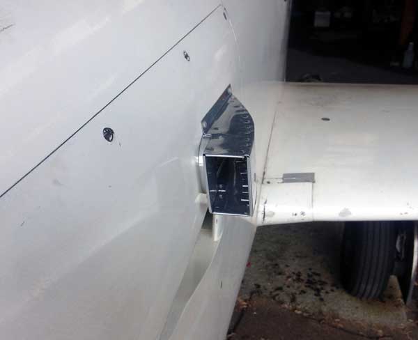
After many delays the tailBeacon went to uAvionix for repair. Nancy and I are going to the East Coast for two or three weeks, so it will not be back on the airplane until mid-September. In the meantime I have accomplished nothing besides adding the stout ground wire -- 14 gauge, as it turned out -- linking the aluminum frame on the aftmost bulkhead to the nearest airframe ground, which is the instrument panel. I was about to cut a hole in the afterbody of the engine/intercooler airscoop for a dedicated flush air inlet for the pilot, but I began to wonder whether putting a NACA scoop on a narrow raised surface was such a good idea. I could put it above the afterbody, but I have been discouraged from doing that by concern that hot air from the various top-surface cowling outlets might get to it. I doubt that could actually happen, but by the time I make up my mind the weather will have cooled off and an extra airscoop will seem less desirable, so the whole project may drag on until next summer. In the meantime Flying Magazine has been sold yet again, with what consequences for me remains to be seen. Flying has been the reason I have been able to spend my life messing about with airplanes; I hope that doesn't change.[July 30, 2021]
At the beginning of July, I got a stern letter from the FAA telling me that my ADS-B performance was not up to snuff, and giving me 45 days to shape up. My NIC was out of tolerance. Don't ask. I got in touch with uAvionix support, and they said it was probably a matter of the ground resistance, which should be less than half an ohm. This was the first I knew of that requirement; I don't know whether I overlooked it when I first installed the tailBeacon or they did not think it worth mentioning. Low ground resistance is easy to accomplish in an airframe made of metal, but takes more attention in a composite airplane, especially when the nearest ground plane -- the instrument panel frame -- is 18 feet away. I had supplied a rather fine ground wire, 20 or 22 gauge, and its resistance was around 1.5 ohms. Apparently it was right on the edge of okay, because I've been flying for more than a year and a half with the tailBeacon and this is the first time the FAA has complained.[June 24, 2021]
Nancy finally finished proofreading Aloft yesterday. She found a bunch of typos and scanning errors, so my rashly publishing the ebook on June 1 was obviously a mistake. If anyone rashly bought it (Rule 1 of software: never buy v.1.0) and would like a copy with the errors fixed, let me know and I will PayPal or otherwise send the $8 so that you don't need to pay for it twice. The paperback version should be available on Amazon in a couple of days. Incidentally, some guy who writes fantasy fiction has chosen to do so under my name, heaven knows why. I am not the author of The Magic Dead (Changeling Saga #3).[June 3, 2021]
A couple of days ago I had a bad runup: big drop, rough, and didn't get any better after I ran up to high power and leaned. The problem occurred when I turned off the mag switch labeled 'L". Did 'L' mean I was checking the left mag, or turning off the left mag to check the right? I wired the system 20 years ago, and it's been so long since I've had a bad mag drop that I'd forgotten what I was thinking back around 2000. I also wasn't sure how the mags related to the plugs -- the leads are a confusing jumble of identical wires -- but I suspected that the right mag assocated with the upper right and lower left plugs. Just to be sure, I asked an A&P, who said there was no hard and fast rule, and that he had even seen systems in which the right mag fed the right cylinders and the left the left -- an arrangement that seems to violate common sense, as he readily agreed. Eventually, on the advice of a different A&P, I ran up to 2,000 rpm, leaned to bring up EGT indications, and checked each cylinder. Turning off one spark plug slows the burn within the cylinder, so that the exhaust gases are hotter when they leave it. When both plugs are healthy, the EGT will rise during the mag check. The effect was not subtle. The EGT on #1 was much higher than the others' with both mags on, and when I switched off the left mag -- that's what 'L' means, as I found by checking the P leads with a multimeter -- it dropped to the peg. No ignition whatever on #1 from the right mag. I replaced that spark plug and the engine ran up fine. The faulty plug looked okay; there was no external evidence of failure.[June 1, 2021]
In a second venture into self-publishing, I have assembled 50 or so articles from my Technicalities column into a book called Aloft, which is currently available from Amazon (mea culpa!) as a ebook and will emerge in paperback form just as soon as Nancy finishes finding typos in the manuscript. It looks like this:

[April 2, 2021]
Yesterday the temperature hit 88, so, while it's still not exactly midsummer in the Rub al Khali, I did a quick oil temperature check using the digital system. The highest I saw was 193 F during a high power climb; cruising, it settled at 177. That is exactly the Vernatherm setting, so I guess the system has been working as expected all along, and my years of intermittent concern over high oil temperature readings were due to nothing more grave than a faulty panel instrument. The temperature did seem to be slightly affected by the cowl flap setting, so I will do some further tests to compare the current arrangement, where the oil cooler air vents into the upper plenum along with the cylinder cooling air, with the alternative, in which the oil cooler air shares a vent with the turbocharger intercooler air and is unaffected by the cowl flaps.[March 17, 2021]
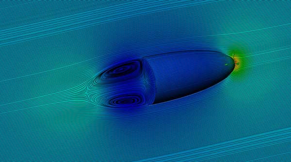
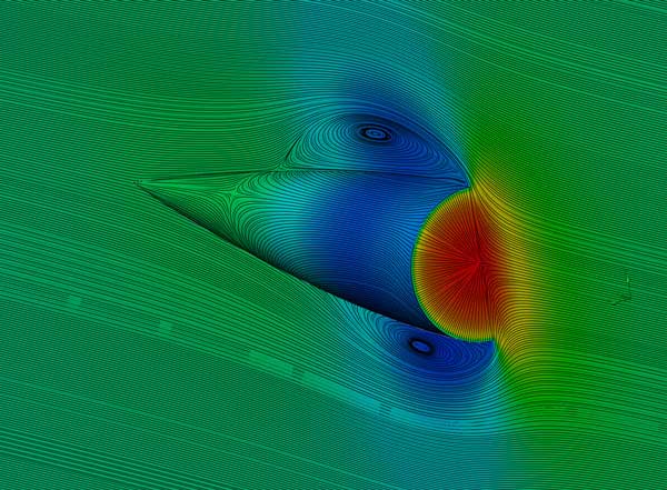
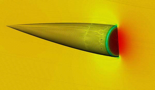
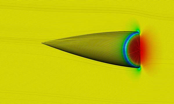
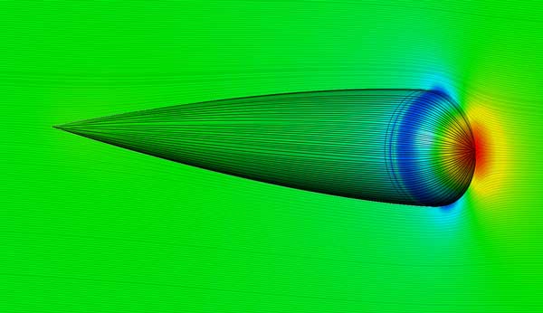
I asked, rhetorically, in the current issue of Flying, whether, if you sliced an airfoil-shaped body of revolution transversely at its thickest point, the bullet-shaped forebody or the blunt-faced afterbody would have the greater drag. My friend Hans Kandlbauer ran some simulations using Solid Works' RANS code, with the following results: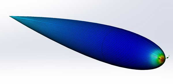
[February 17, 2021]
I did a cold compression check. All three cylinders on the right side of the engine were 80/80. the three on the left were 42, 64 and 71. This seemed odd, so I ran the engine for five minutes at 1,200 rpm, then shut down and repeated the check on #6, which was the lowest; it now showed 80/80. I don't understand compression checks; it seems as if you can get just about any result on any given day. The asymmetry is puzzling, however.[February 10, 2021]
A friend forwarded me a picture, taken by a friend of his, Elwood Schapansky, of the original Melmoth at Galena, Alaska, in July, 1976, a few days before Nancy and I flew over to Japan. I am surprised to see that 1) the airplane was so clean; and 2) the down jacket, which I still have, was once so puffy.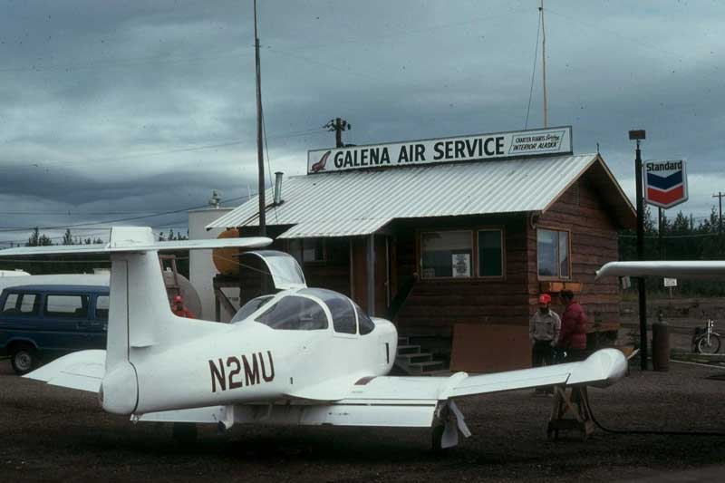
[January 8, 2021]
Oddly, it has now happened twice that the new micro-camera stopped working as soon as I took off. Today, however, I did get a gratifying speed point at 14,000 ft DA, 181 ktas at 9.2 gph, 63% power, which is slightly better than the computer simulation predicts.[December 19, 2020]
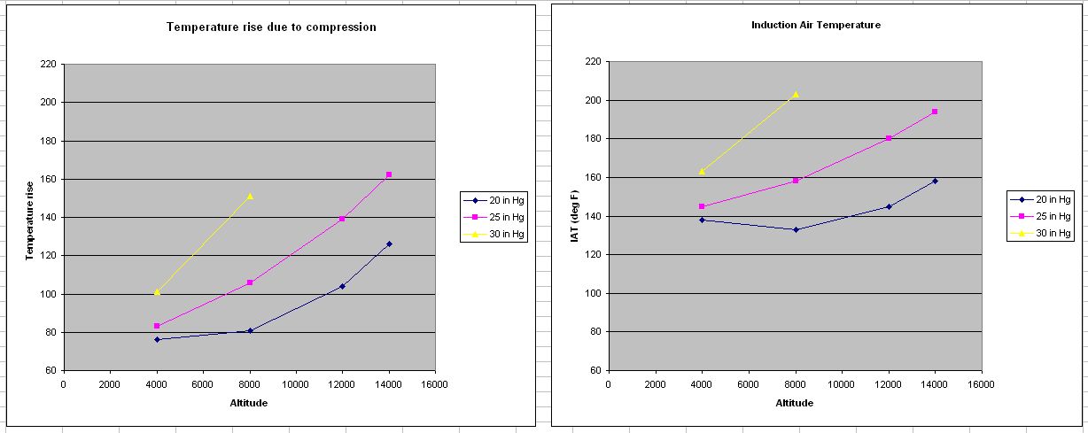
Last week was notable for ridiculousness. I re-did the calibration of the MS-28034 induction air temperature probe, and checked a spare as well (I have three -- the third is the oil temp probe). Both returned horrible calibration curves, with a true 100 deg C reading as 125, and 40 reading as 55. Since it is unlikely that two probes are identically faulty (and the oil temp, which I did not test, also indicates unexpectedly high), it seems probable that, as a friend suggested a few weeks ago, the problem is the three-gauge panel display, which is probably coeval with the B-47. If this is the case, then all my worries about oil temperature have been unecessary, since it has actually been in a reasonable range all along.[November 30, 2020]
Before Thanksgiving I moved the IAT probe, which is about 1/4 inch thick and a couple of inches long, from its position at the entry to the throttle body to one in the middle of the intercooler outlet tank. I did this in the hope that the asymmetry it created in the throttle body flow, which it entered from one side, might be responsible for the odd difference between EGTs between the right and left cylinder banks. The change turned out to have no appreciable effect. CHTs have always been very inconsistent front-to-back, but they do not show the same right-left imbalance as EGTs do. Yesterday at 12,500 ft d.a. I recorded these CHTs (Celsius) with partially open cowl flaps, ordered front-to-back:[November 14, 2020]
I added a heat shield to the portion of the duct leading air to the oil cooler. The result -- with the not negligible help of cooler weather -- was that the oil temps are now in the green. The temperature of air entering the cooler is now about 4 deg. F above ambient, so there is still some heating taking place on the way from the cowl intake, but it's slight. The temperature rise in the air passing through the oil cooler is around 75-80 degrees F. It was apparent that the vernatherm was working as intended, since there was no temperature rise in the air passing through the cooler until the oil temperature hit 160 F.
The oil temperature turns out to be quite sensitive to the position of the cowl flaps, which regulate the pressure drop across the cooler and the amount of air passing through it. This was the reason I originally provided the oil cooler with its own exhaust duct, separate from the cylinder cooling air. With cowl flaps open, oil temp was 185, fully closed 215.
I finally got a speed point -- 178 ktas at 9.6 gph at 12,500 ft -- that more or less matched predictions for an equivalent flat plate area of 2.35 sq. ft, so the intercooler and the pitot-style scoop on the side of the cowling have not added a huge amount of drag. They've added some, however. Maybe I should have a way to shut off the intercooler when I don't need it.
[November 2, 2020]
The duct is now installed.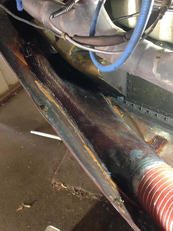
[October 21, 2020]
I see that it was just shy of three years ago that I contemplated providing a direct duct from the cowling air inlet to the oil cooler, to avoid an admixture of exhaust-warmed air. I have now almost finished the mold for this duct: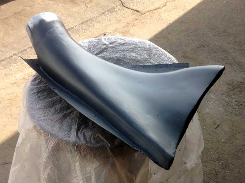
[October 13, 2020]
The oil and air temperature probes, which share the same indicator via a toggle switch, both read high on the ground (on a 38 deg C day. they read 50 C) but say 100 C when immersed in a can of boiling water; so they're okay. I decided finally to provide a separate supply of cold air to the oil cooler, and I am making tooling for that duct now. Now that the oil cooler will no longer be sharing an outlet with the intercooler, I can probably replace the hood over the opening with shark gills.[September 24, 2020]
No peace unto the wicked. I took out the nice oil cooling air outlet plenum and duct that I was so pleased with, closed up the holes it left, and moved the pressure probe line to the top of the (now intercooler only) outlet pan. The OAT was slightly higher than yesterday's: 94 F on the ground and 71 at 8,500 feet, or 42 degrees F above standard. Despite the change in the oil cooler arrangements, during the climb the oil temp went up to 240 F, same as before, and settled back to 230 in cruise.[September 23, 2020]
I collected a few pressure points from the plenum immediately above the oil cooler. To my surprise, the pressures there were quite high, even though the outside world is 12 inches away through a 10 sq. in. duct. Two representative values were 3.8 in. H2O at 120 kias and 5.1 at 140 kias. These correspond to delta-p's of 3.5 and 5.4 inches respectively. What is surprising about this is that the delta-p's across the engine are 6.5 at 120 and 7.9 at 140. In other words, I would get better delta-p across the oil cooler if I closed the external duct and simply let the oil cooling air spill into the upper plenum. This was the original arrangement, before I started messing with it about 10 years ago. I now intend to try reverting to it.[September 22, 2020]
I finally managed to get some video of the scoop tufts, but now I can't figure out how to download the video from my iPhone. However, I did some screen grabs, of which this is one: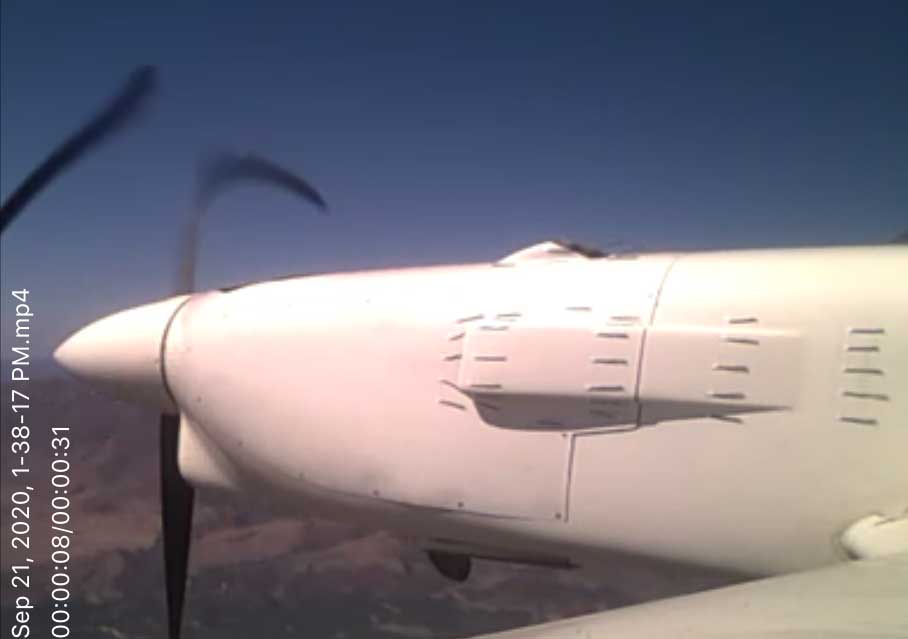
[September 12, 2020]
I tufted the scoop and then made two attempts to record video of the tufts in flight. Neither was successful. I belatedly realized that the camera rig I was using had no on-off switch, and was activated simply by connecting the battery to the camera. The charging port is on the camera, however, and so to charge the battery one must connect it to the camera. I had not done so, and when I turned it on before flying the camera would work for just long enough to persuade me that it was okay, but, once I was airborne, quit. I can see some of the tufts from the cockpit, and they were lying down nicely. Tufts are typically made of a loosely woven yarn, and one telltale sign of flow separation is tufts that are unravelled after flight. Tufts in smooth flow are undamaged. The only frayed tuft I had was one right in front of the center of the boundary layer channel; I suppose it may have been whipping back and forth across the stagnation zone.
In the course of the last three flights I noted unusually high oil temperatures. The ambient temps have been around 40 degree F above standard -- that is, in the high 90s -- but even so the oil temp is higher than expected. I checked the pressure in the lower plenum and got the impression that it's down a bit, perhaps because of leakage into the collector pan from which the intercooler and oil cooler air are vented. The pan is stationary -- it does not move with the engine -- and so I am removing its flexible perimeter seals and replacing them with a rigid barrier that will press into a rubber sealing strip on the inside surface of the cowling. There could be other reasons for the increased oil temperature, but since all are potentially more dire or difficult to deal with than this one, I might as well start with this.
Last Tuesday I climbed through smoke to 5,000 feet, hoping to get on top, but with restricted forward visibility -- impossible to tell whether it was three miles or half a mile -- and with the ground disappearing below me, I turned back to the airport. Yesterday and today the smoke has been dense, down to the ground, its campfire smell pervasive, the sun a faint orange disk or entirely invisible, all around an infernal and shadowless scene.
September 2, 2020]
[August 7, 2020]
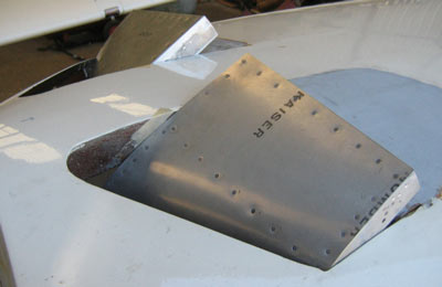
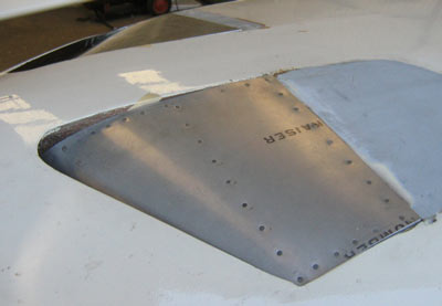
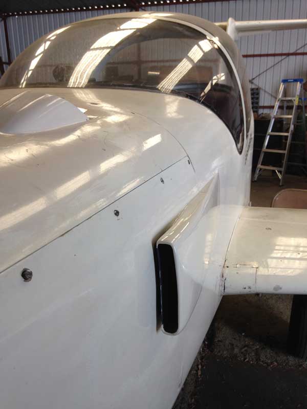
The outer form of the scoop is now complete; only the afterbody behind the cowling parting line remains to be laminated, and then the whole thing needs to be smoothed and finished. The ivory paint with which I originally painted the plane 17 years ago, and of which I still have a serviceable can, now seems to cure with a faint purplish hue, so the repainted areas around the new inlet and outlet will be rather conspicuous; but no one has ever accused me of being overly fastidious about paint. Call it Murano.[July 30, 2020]
I finished the inner liner of the new airscoop today. (When I flew the other day, the front 4.5-inch duct and the boundary layer channel were not yet installed.) This will now be covered with a layer of foam, which will be sanded to a streamlined shape and glassed over. The inlet is 7 inches wide and 1.25 inches deep, and the boundary-layer channel is 3/8 inch deep. The afterbody will extend a little past the firewall along the side of the cabin and will incorporate a small flush scoop for the pilot's ventilator.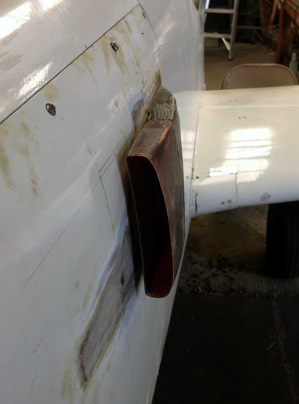
[July 24, 2020]
I flew today with the new air inlets partly installed. At present only the inner surfaces are in place; the outer fairing is yet to come. I was curious to see what speed penalty the sharp-edged, lipless excrescence would exact. At 10,500 ft, where the density altitude was 12,500, 9 gph gave an indicated airspeed of 143 for a true of 172. This is about three knots shy of what the computer model predicts. On the other hand, at 7.8 gph it was 138 kias (166 ktas) which coincides exactly with the model. So I suppose things won't be noticeably worse once I have the smooth fairing built.
[July 21, 2020]
I've been spending a couple of hours a weekday on the seemingly endless task of replacing the air inlets for the engine (NACA flush, very pretty) and intercooler (crude metal kludge) with a single pitot-style scoop. I am very sorry to lose the NACA inlet, the look of which I have always liked, but regret, as both Chief Seattle and Marlon Brando have said, is useless. I intend to incorporate into the afterbody of the scoop a smaller NACA inlet, a sort of consolation prize, to provide air directly to the pilot's ventilator. In the present arrangement, a single inlet on the right side supplies both pilot and front-seat passenger, and it is not too satisfactory for the pilot on hot days if the passenger-side vent is open. The two back seats share a single ventilator, but it produces a surprisingly powerful blast of air, as Russ Hardwick and I discovered to our sorrow when flying at a frigid 15,500 feet a few years ago. I resolved then to provide the pilot with the ability to shut off that ventilator, but have not yet done so.[May 27, 2020]
I found a nice picture online of M2 leaving Oshkosh in 2011. Takeoff flaps have not yet been retracted. This reminded me that there are still some bits that need paint. I wrote to the copyright holder asking for permission to post the picture on this site. I have not yet heard back -- it's been a couple of weeks -- but if he refuses I'll take it down. So study it carefully now.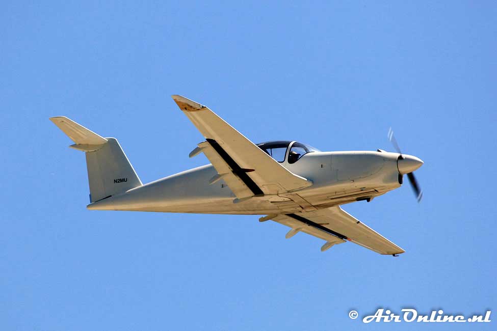
[May 2, 2020]
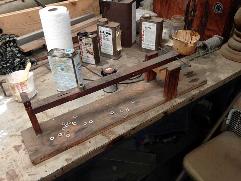
To convert the geyser emerging from the top of the cowling into a more-or-less aft-facing plume, I removed the hood from the now-disused oil cooler outlet with an oscillating saw -- marvellous tool! -- cut it in half lengthwise, made it an inch wider, and tacked it over the new outlet with some fancy turning vanes added. I am now laminating this into place, and in the process am revisiting my long-neglected epoxy-metering equipment. My ratio pump is too gummed up to use without a thorough cleaning, but I find that a simple balance beam is almost as fast. In the past I used this method, when I used it, quite stupidly, piling up certain number of washers, moving them right or left to balance, and then increasing their number as needed to achieve the desired ratio when the second part was added. This time around it finally dawned on me to make a mark 10 inches from the balance point, and other marks at 12 inches and 14.4 inches, representing respectively the mix ratios for West System and EZ-Poxy. You put your empty mixing cup into the ragged-looking cup at the right-hand end and balance it with the big nut. You then pour resin into the mixing cup, balance it with washers at the 10-inch index -- you can precisely match the washers with a few extra drops of resin, if need be -- and then move the stack of washers to the appropriate index and add hardener to balance. I can't believe how long it took me to figure this out. Not so smart after all.
[April 17, 2020]
Initial test flights produced mixed results. Induction air temperature dropped by 30 deg C, from 65 to 35, with an OAT of 19 C. I'm not sure how good that is, but anyway it's going in the right direction. On the other hand, the oil temperature, which I optimistically expected to be lower than with the previous arrangement, initially settled at the top of the green, but then started creeping upward. Suspecting that this might be related to the fact that air from the oil cooler and air from the intercooler approach the outlet from opposite directions, I landed, taped over the intercooler air inlet and took off again. The oil temperature got even higher, which made no sense at all. On landing and removing the cowling side panel, I found that the neoprene gland at the bottom of the oil cooler duct had partially prolapsed, probably because of the large pressure difference across it. I'm not sure how that would affect oil temperature, but at any rate it's something that needs to be fixed. At the moment it's held in place by friction; I'll try a hose clamp. The tufts that I had affixed around the outlet on top of the cowling resembled the scene when a car collides with a fire hydrant; I began work on a hood.
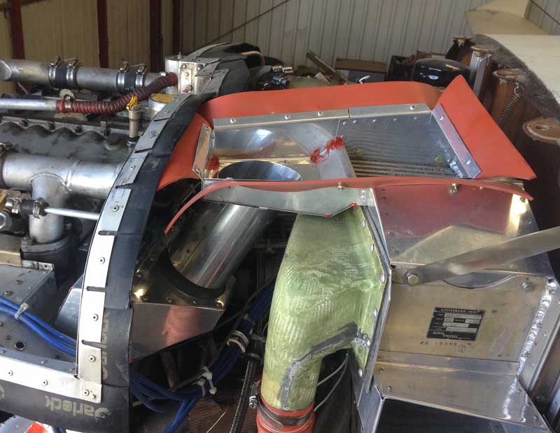
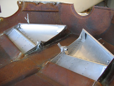
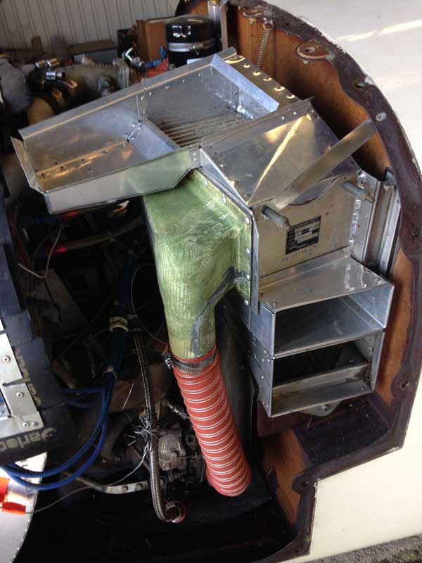
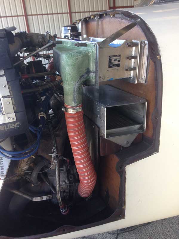
Here at last is the finished ducting for the intercooler and the oil cooler. Spent oil cooling air now goes into a box that protrudes through the rear baffle, and thence through a 3.5-inch duct into a plenum shared with the intercooler. The plenum vents through the top of the cowling; I am bandaging that wound now, and I hope to be able to test-fly the system by the end of this week. If all goes well, I will then turn my attention to the airscoop on the side of the cowling. It will replace the odd pairing of a crude temporary metal scoop and a slick NACA flush inlet (see below) and will provide air to both intercooler and engine. I shall draw my inspiration from the scoops on top of the cowlings of the DC-7 in which I took my first plane ride at the age of 10.
[March 25, 2020]
Today I added the flexible baffles to the air outlet box; tomorrow I'll cut the dreaded hole in the top of the cowling. Yesterday I flew with a temporary airscoop feeding cooling air to the intercooler. The air, having passed through the intercooler, merely flowed into the cowling. Nevertheless, the induction air temperature was lower than usual. The scoop is homely, but at least it has its own boundary-layer channel:
Progress on the intercooler project, which began two years ago, has sped up markedly. One of the reasons for this -- not, I'm sure, a very sensible one -- is that I would like to get the system finished, along with the oil cooler ducting to the new hot-air cloaca on top of the cowling, so that the plane is at least complete, if not clean, in case I contract COVID-19 and die.
[March 13, 2020]
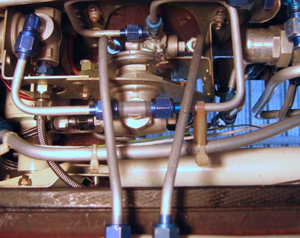
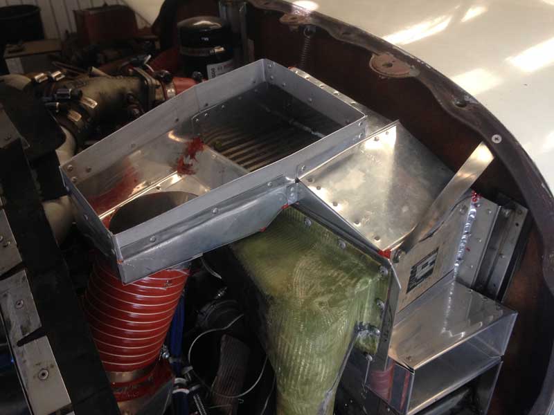
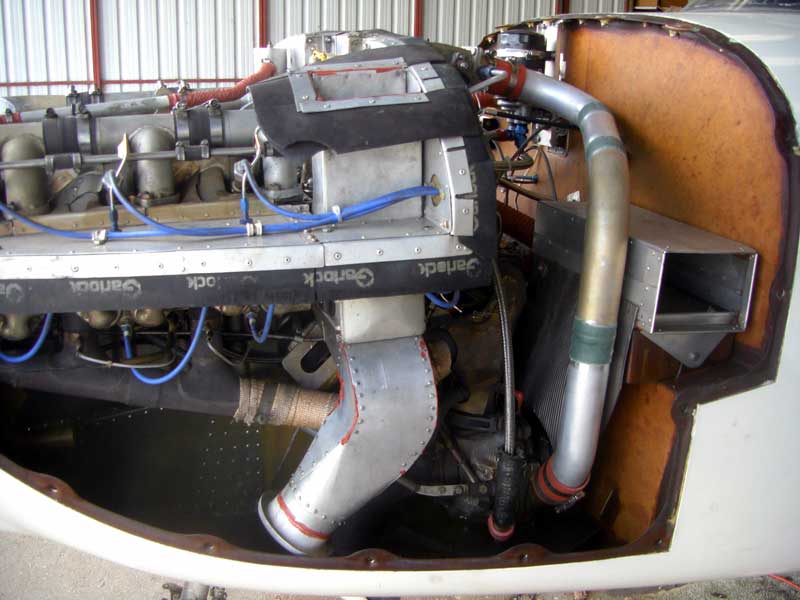
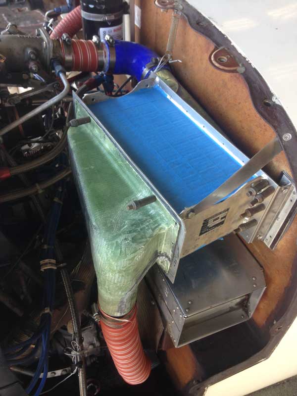
The intercooler is now equipped with its inlet and outlet ducts. The inlet is the upper of the two rectangular openings below the intercooler; the lower one is the engine induction air filter box. The outlet is the tray on top, which is eventually intended to receive both intercooler and oil cooler air and send them out a louvered vent on top of the cowling. The current protruding outlet for the oil cooler will disappear. I've partially built the duct in the side panel of the cowling that will bring cooling air to the intercooler, but I haven't cut the hole in the cowl side yet -- I hate cutting into these pristine surfaces. Also, I have been busy lately with an apparatus from which the ashes of an old friend will soon be scattered into the Pacific Ocean.
[January 22, 2020]
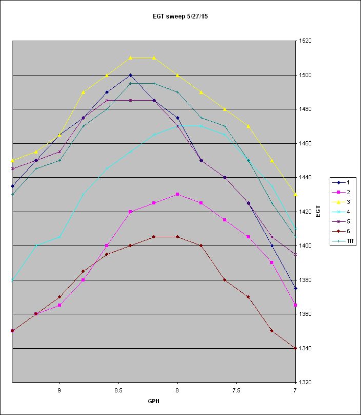
The Christmas season is hopeless for getting any work done on the airplane, as I have regularly complained before. Early January does not seem much better. I did collect some rough data on EGTs, and found that while messing with the induction did not noticeably affect the synchronization of peak EGTs, it did somehow or other cause the right-side cylinders to collectively run at higher EGTs than the left-side ones. I asked George Braly at GAMI about this, and after offering various comments and suggestions he added a quotation from Richard Feynman about the easiest person to fool being yourself. I have often fooled myself in the past, and am prepared to believe that I am doing so again now. After I have the intercooler plumbing completed I will do a careful survey of EGTs and possibly add a flow straightener or an adjustable vane just ahead of the throttle inlet in order to equalize the flow to the two intake-manifold logs.
In my previous entry I bashfully admitted to having made a really beautiful landing on a particular flight. Well, I am about to do so again. My landing yesterday was perfect. I feel free to say this because while Melmoth 2 is not a difficult airplane to land well, I seldom manage to get all aspects of the landing to work out perfectly, and so I either land at a slightly higher airspeed than ideal, or with more of a tap (or bang), or I don't put the nosewheel down as gently as I would like to because I run out of tail authority (being alone, and therefore noseheavy). There are some tall things sticking up just across the street from the approach end of Runway 12 at Whiteman, and, although you'd have to be awfully low to actually hit one, I tend to come in a bit high and chop the power just short of the end of the runway, with the displaced threshold still several hundred feet ahead. The glide steepens noticeably before I begin to flare. Ideally, the nose is still coming up as the tires get within a few inches of the surface. I like to get the nose really high, stall warning blaring, and on touchdown -- nearly imperceptible, of course -- lower it with sufficient control to arrest the wheel just before it touches and place it gently on the runway. At that point the speed is under 40 knots and I easily make the midfield turnoff. There is nothing extraordinary about any of this; it's really just a matter of chance to get all components right. But, as any pilot knows, it's a good feeling when you do.
[December 14, 2019]
The intercooler passed its first functional test, viz. it did not fall out of the airplane during its first two flights. After suitable delays for meleagricidal late-November activities, I got the outlet tank re-contoured, boldly sawed a 90-degree bend out of the existing duct, and put it all back together. At first it appeared that replacing the short elbow with a long one had made no difference, since on runup I found that the right-side EGTs were still much higher than the left-side ones. It then dawned on me that I had never established a baseline; I had merely assumed that since EGTs are pretty even in cruise, they must be in runup as well. For that matter, I never look at the EGT or CHT during takeoff, and so my impression, during the first test a couple of weeks ago, that CHTs were rising ominously may have been spurious.
I removed the intercooler again -- I've gotten pretty good at it -- re-installed the old duct and did a run-up, which revealed exactly the same behavior. It may be that even the short elbow was not having the enormously detrimental effect on mixture distribution that I thought, but the 6-inch radius aluminum duct looks a lot better. I put the intercooler back in, flew to Santa Paula, bought some relatively cheap gas ($4.35/gal vs $5.59 at Whiteman), and flew back to Whiteman, where I made, I must say (because I can't always), a really beautiful landing.
At present the intercooler is just a rest stop along the way from turbocharger to throttle body; I have not yet made any provision for cooling air to flow through it.
[November 23, 2019]
It turned out that the outlet "tank" could be shortened fairly easily to accommodate the same aluminum elbow of 6" radius as is now part of the pipe that runs from the turbocharger to the throttle body. I just need to do a little sculpting with filler -- a mixture of epoxy with plastic microspheres for lightening -- to smooth the internal contours of the tank. The intercooler will then be rigidly supported at its inboard end -- no more spring -- and sufficient (I hope) flexibility will be supplied by joints at both ends of the aluminum elbow. There is no guarantee that the flow distribution in the intake manifold will be entirely unaffected by a heat exchanger replacing a length of straight pipe; but I think the effect, if any, ought to be much less than that of the villainous blue elbow of yore.
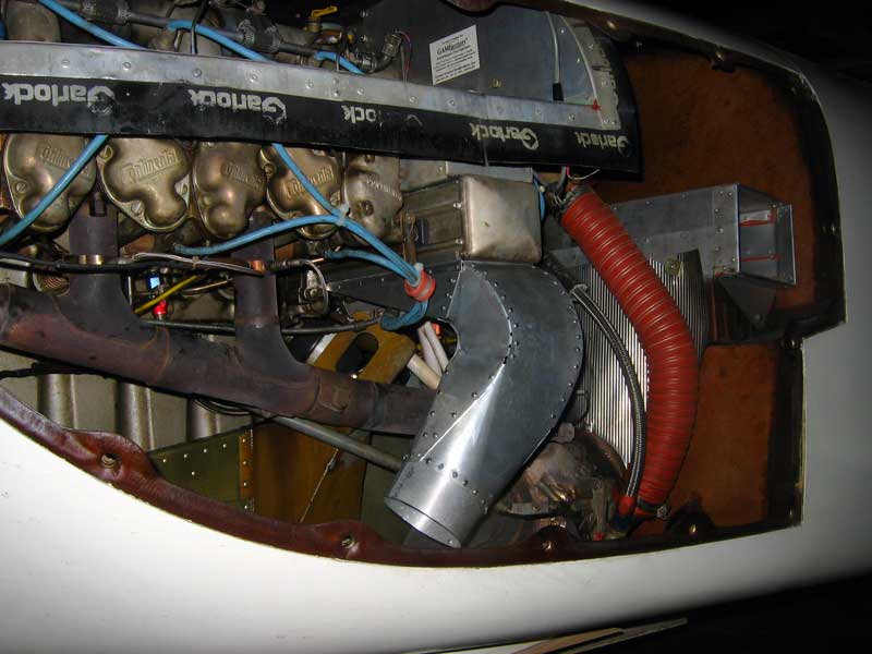
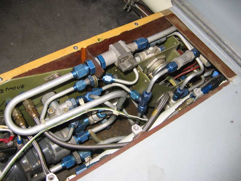
Going back through this chronicle, I see that I never supplied a picture of the present plumbing connecting the turbo to the intake manifold. This is it:
The long duct consists of a bunch of pieces of .035 wall aluminum tubing spliced with bands of fiberglass cloth and epoxy. I don't know where I got the tubing, but I wish I had more of it. I will have to saw the 90-degree bend out of the top end. I would prefer to keep the old duct intact in case the new arrangement doesn't work; but there's no choice.
[November 15, 2019]
Physics 1, Hope 0.
At least I was not so naive as to be unaware that that short elbow might cause trouble. I just hoped it wouldn't, and told myself you never know with fluid flow, which is true, generally. However, by the time I was halfway to the runway for the first test flight, it was obvious that the right side of the engine was running much leaner than the left. I began a takeoff, but aborted it when after a few seconds the CHT I was monitoring (#3) hit 200 deg C (392 F). Normally, the engine does not get to that temperature until I am well established in the climb. I returned to the hangar, removed the intercooler, put the old duct back into place, and went flying.
I need to revise the shape of the duct on the outlet side of the intercooler to allow a bend with a radius of six or seven inches between it and the throttle body. That is the radius of the bend in the current pipe, and it works fine. But this puts me back in search of a 2.25-inch I.D. hose sufficiently strong to handle 1 atm. of overpressure at, say, 250 deg. F, and sufficiently flexible to 1) make a 6-inch radius bend without wrinkling on the inside and 2) allow some freedom of movement between the engine and the intercooler.
[November 7, 2019]
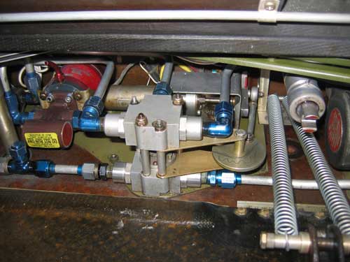
After much hesitation about how and where to mount the intercooler, I settled upon the above arrangement. The difficulty is that the intercooler is secured to the airframe, but connected to the engine, and the distance from the throttle body to the intercooler outlet is too short to allow for the full range of motion of the engine. The solution I am trying -- which may be no solution at all -- is to mount the outboard end of the intercooler to the firewall with a flexible shear clip made of .016 stainless steel sheet. A diagonal strap removes bending loads on the mounting lug, which is bonded directly to the honeycomb firewall and should, in principle, experience only shearing forces parallel to the firewall surface and a compressive force against the firewall. At the inboard end, a coil spring provides several pounds of lift, so that the flexible duct is not carrying the weight of that end of the intercooler. The inboard end of the intercooler does have some freedom of movement, however, to allow for the engine jumping around during startup and shut down. I'm not happy about the very tight elbow, but it was all I had room for even though I used the shorter of my two intercoolers. I started the engine today just to confirm that the assembly did not immediately fall apart. The next step will be to attach the fiberglass ducts to the intercooler and re-run the inflight EGT survey to see whether the elbow is affecting the mixture distribution. If the system passes that test and doesn't disintegrate in a few hours of flying, I will add the ducts for the cooling air.
[August 26, 2019]
The inlet and outlet ducts are finally, albeit temporarily, attached to the intercooler:
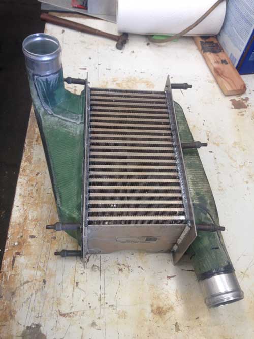
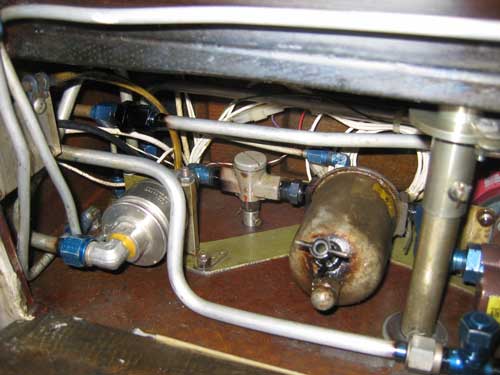
In the picture the intercooler is upside-down; the pipe on the left connects to the turbocharger, which is below it, and the one on the right goes to the throttle body. It actually fits into the airplane like this:
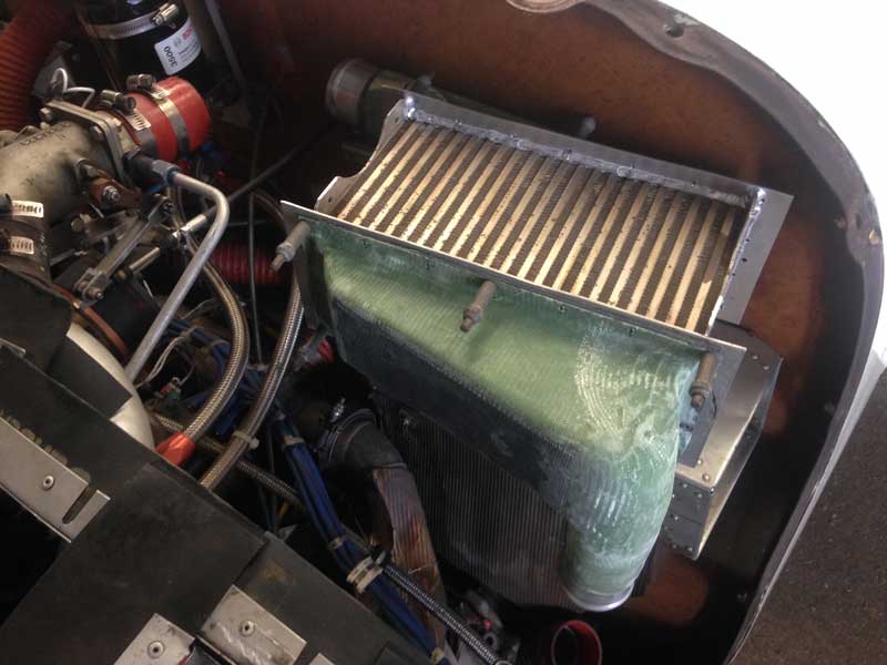
You can just see the turbo outlet as a dim red crescent at the bottom of the picture.
My present plan is to provide a pitot-type (i.e. non-flush) inlet for the cooling air, because flush NACA inlets are not effective unless there is a negative pressure gradient downstream. The cooling air will vent upward out of the top of the cowling. I plan to remove the present hooded outlet for oil cooler air and vent that air to the same outlet as the intercooler's.
[July 30 , 2019]
A week ago I finally took the intercooler to a welder to add the flanges to which the charge air ducts will be attached. I got it back yesterday. Since I changed my mind about which to use of the three intercoolers I have collected over the years, I had to saw about four inches off the outlet duct, which I had already made, and I will have to modify the inlet duct mould similarly before making that part. After lengthy mental calisthenics visualizing various ways in which the intercooler could be installed, I finally concluded, by dint of propping it up in place, that my first plan -- that of March 23, 2018-- was the best, or at any rate no worse than any other. Getting fast-moving induction air around the corner from the intercooler outlet to the throttle body inlet requires a 2 1/4" I.D. flexible elbow with a 7-inch radius of curvature. I found something at McMaster-Carr that should work. I also found ready-made aluminum tubing segments with beaded ends, which I will bond into the laminated ducts. So the design and materials of the induction air plumbing are more or less settled. As for the cooling air, I am leaning toward a pitot-style external scoop for both the intercooling and induction air, located where the NACA flush scoop is now, and some sort of louvered outlet on the top of the cowl, directly above the intercooler. I am also thinking of ducting the oil cooling air to that same outlet and dispensing with the hooded vent I am using now. The drag penalty of an external scoop and an additional heat exchanger is hard to foresee; if it represents an increment in F, the "equivalent flat plate area", equal to the frontal area of the inlets, it will be barely acceptable in exchange for cooler induction air and greater detonation margins.
[June 1 , 2019]
Nancy and I got back from a week-and-a-half trip to the east -- college reunion -- this morning at 2:00 a.m. I was planning to fly up to Paso Robles for Chuck Wentworth's annual Antique Aero BBQ, but LA has been socked in all day and I'm not remotely current, so I stayed home. This has given me time to think about all the things I need to do, mostly tedious. Having relieved the AT-50's 12-volt power supply of its duties, I now have to find another job for it. M2 has two of those Narco 24-to-12 converters, actually; I think the other powers a 12-volt outlet. Can I simply hook them together, in parallel, or would that engender inner conflicts? (Being ignorant of electronics, I have to launch queries like this into the ether, like Noah's dove.) Poking about back there also reminded me that I have never connected my pitot and AoA tab heat -- not that I will ever use those things in my ever-less-ambitious flying. Furthermore, installing the new transponder somehow caused my glideslope receiver to quit working; a loosened connection somewhere, no doubt. The intercooler, meanwhile -- like Hope, it is forever deferred, but never extinguished -- awaits the creation of the second "tank" and the addition to the heat exchanger of a couple of aluminum flanges to which the tanks will be secured.
While we were in the East, by the way, an unusual event occurred. Someone streamed Jaws, and, of the four people present, three -- Nancy, our daughter Lily and I -- had never seen it. A genetic thing, I guess.
[May 5, 2019]
A couple of days ago I did another evaluation flight and requested a PAPR report from the FAA. It came back with exactly the same fault as before I changed transponders, and not only the same fault, but almost exactly the same percentage of non-received Mode 3A squawks. This time, however, I heeded the advice on the FAA site to contact them before heading off to the radio shop. I got a very prompt and nice reply saying that the dropped squawks were due to being at low altitude or behind mountains or otherwise out of coverage, and my equipment appeared to be working fine. So I guess I can start thinking about something else for a change.
[April 24 , 2019]
Success! Today everything worked. Or let's say, at least, that I was unaware of the things that were not working.
[April 23 , 2019]
Installing the new transponder was more of a job than I anticipated, but after a day of fumbling around I got it and the wire harness installed. The Narco transponder used 12v power, and required a power converter; the Garmin is omnivorous, and so the connection between it and the bus had to be rewired. The power converter remains in service for a few other 12v things. Making the new connector for the Garmin turned out to be the simple part; I got a beautiful little crimping tool online for $30, and putting the right wire into the right hole was not much of a challenge, except in one instance where, in the twilight of my years and workshop, I mistook a dark brown wire for a black one and as a result deprived the altitude encoder of its ground. When I first powered up the transponder yesterday it was not displaying altitude -- this was due to the missing ground -- but appeared otherwise correct. When I got into the air, although the "reply"indicator was blinking in a realistic way the tower was seeing no return. Today I fixed the missing ground and re-installed the fitting on the transponder end of the antenna cable. The transponder now displays altitude -- correctly, to boot -- but I ran out of time and will test fly it tomorrow.
[April 12 , 2019]
One of the two intercooler tanks is now done. Unfortunately, I took a second look at the heat exchanger core that I had decided not to use, and I began to think that I might be better off with it than with the one I had first chosen. It's shorter, and will give me a little more freedom in arranging the parts of the system and their associated ducts. That means that the tank I have made is too long; but it will not be difficult to shorten it, and also the mold for the other, if that is what I decide to do. In the meanwhile, after what seemed to me a torturously long delay, I finally got the Garmin 327 transponder, which is supposed to be the solution to the Tailbeacon-related issues, and have been making up the wire loom for it and installing its remarkably stout steel rack in place of the AT-50A's aluminum one. I hope to be flying again by the end of next week. The airplane has not been in the air now for more than a month.
[March 22 , 2019]
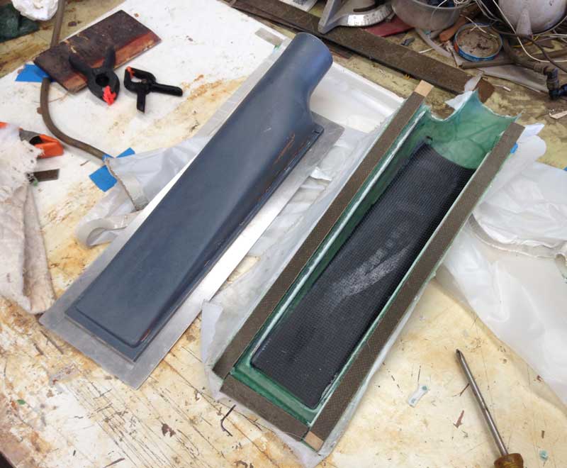
I finally got back to the intercooler project after 10 months of idleness. The first of two layups of the outlet "tank" appears to have been a success, to the extent that 1) the epoxy hardened and 2) the part came off the mold without my having to destroy either. The part consists of four plies of glass with carbon fiber facings on the inner and outer surfaces of its relatively flat back. It's laminated with a high temperature Hysol epoxy. A second portion will be laid up covering the underside of the round tube, and overlapping, but not bonded to, the first. The final operation will be to bond the two parts together around a short length of aluminum tubing, without the male mold inside. The parts for the inlet tank are broadly similar.
Paul Lamar, the rotary engine advocate, gave me a bunch of books, including the classic Kuchemann and Weber text on internal flow systems. It reminded me of what I already knew -- because I made the oil cooler outlet duct that way -- but evidently forgot while I was designing the intercooler outlet tank, namely that while the inlet (that is, the high-pressure side) can be wedge-shaped, the outlet should be more like a rectangular box with equal clearance across the whole face of the heat exchanger. The effect will be to make one end of the intercooler less effective than the other. The whole thing is probably bigger than it needs to be, however, so the design is non-optimal from the start.
In the meantime, my transponder has been at High Desert Avionics at Fox Field for almost two weeks, waiting for an adjustment which I hope will allow the system to pass the FAA test. It almost passed on the second try, and what it did not do well was something that, if I understand it correctly, was due to the transponder, not the Tailbeacon.
[February 18 , 2019]
A correspondent who spoke with the Tailbeacon people told me that they pronounce it "you-Avionics", which is the least logical of the possibilities, unless they are trying to appeal to the "me generation". Another correspondent expressed concern over the thing being hard-wired on at all times, since that exposed it to voltage transients on engine start. He suggested putting it on the avionics master switch. There was no avionics master switch -- the first Melmoth didn't have one either -- but I decided to capitulate and add one. This turned out to be easy to do, since all of the avionics breakers are in a single row on the breaker panel. I used the old master switch from Melmoth 1, which is a somewhat bulky thing that you have to pull outward to toggle, and I put it over on the right side of the panel, beside the breakers, on the theory that if switching the avionics on and off involves a somewhat unusual group of motions, I'm more likely to remember to do it.
[January 29 , 2019]
First of all, it turns out, when you look closely, that the name of the company that makes the Tailbeacon is not actually uAvionix but mu - Avionix, that is, Greek letter mu, meaning micro. So I don't know how to pronounce it. Is it you-avionics, mew-avionics, or micro-avionics? In any case, I tried an FAA acceptance flight, which basically involves flying around for half an hour and making a few 360-degree standard-rate turns. You then get online and ask an FAA computer somewhere for a report on the quality of your ADS-B out returns, and in a minute or two you get an email, which said, in my case, that the system did not meet the requirements.
The next step is to use a cellphone app to adjust the sensitivity until the beacon and the transponder get into sync. It requires having regular transponder interrogations, so I have to find an airport around here where I can be on the ground (the app works only on the ground) and the transponder is blinking. I changed some wiring around so that the tailbeacon and its integral tail nav light are always on when the master switch is on; only the wingtip lights are switched from the panel. While I've been fiddling with this, two unrelated things went wrong: the attitude indicator tumbled (and would not untumble on subsequent flights) and the Lowrance GPS went dark. I sent the AH out for overhaul; the problem with the Lowrance turned out to be a blown fuse. I don't know why it even has a fuse, since it's on a breaker; but anyway, I put in a new fuse and it's working again.
This is what the beacon looks like (the thing next to it is a halogen flasher that I use in lieu of a strobe):
![]()
[January 17 , 2019]
In December I finally sprang for an ADS-B out transmitter. I selected the uAvionix Tailbeacon for a number of reasons, not least its price of $1,600. Still, only a diamond ring would cost more and come in a smaller box. Its installation, which I did a few days ago, involves an absolute minimum of alteration to the airplane. It simply replaces the tail light. When it is installed on a TC'd airplane the nav lights have to be kept on at all times; I intend to separate the tail light power supply and ground from those for the wing lights and run only the tail light/beacon continuously. I don't know how the thing works, but I assume that it just listens for a squawk from my extremely legacy Narco AT-50 transponder, and when it detects one it tacks on a few extra syllables of its own to report my ID, position and altitude. I am hoping that my Stratus 1, iPad, and the Tailbeacon will keep me flying in the ATC system for a few more years. I heard some dire grumblings about this being the first step toward user fees, which general aviation has been opposing for the past half century or so. Maybe, maybe not. I remember when the transponder requirement was denounced as the final nail in the coffin of our liberties.
One question that people ask about the Tailbeacon is, if it's entirely self-contained and just screws onto the taillight mount, what's to stop somebody with a screwdriver walking off with it. Well, first of all it's associated with a particular airplane -- you program it through your smartphone -- and you need a secret password to change that. Furthermore, the two #4 screws that hold its mounting plate in place end up behind the antenna, so you can't get at them with a screwdriver. The gadget itself locks into the base with two tiny allen screws, and unless I am mistaken they are either metric or of a strange intermediate size, because only the wrench that came with the beacon was able to engage with them.
It might be easier to steal the propeller.
[January 10 , 2019]
Looking through some old files, I came upon a letter that Mike Melvill wrote in 2002, when he was helping me fly off the 25 hours to get Melmoth 2 licensed. In it he reported the results of some speed tests. I thought it would be interesting to compare these to present performance, so yesterday I went up to duplicate at least part of his tests. I quickly realized that this could not be a very meaningful exercise, because at the time he did the tests the airplane did not yet have static ports, relying instead on cabin pressure for a static reference. Cabin pressure is generally below ambient because of leakage around the windows into the low pressure around the canopy, and so his results would be on the high side. Furthermore, at that time the airplane did not yet have a fuel flow meter, and so a direct comparison with the way I determine power setting today was not possible. Mike had recorded both fuel pressure and EGT, but much had changed about the engine since then, and I was now unable to duplicate his conditions. I gave up the intended comparison for a lost cause, but I did record a series of speeds at a density altitude of 11,000 feet, 2,500 rpm, and manifold pressures from 18 to 28 in. Hg. Not surprisingly, these coincided well with my computer model, which at this point does a pretty good job of impersonating Melmoth 2. Eleven gallons an hour, or about 75% power, produced 190 knots true airspeed. This would go up to around 197 ktas at 18,000 feet at the same fuel flow. Too bad; an even 200 would be nicer. Maybe if I ever get around to making the tires narrower. From the point of view of comparing 2002's performance with today's, the outing was a bust, but it proved fiscally fortunate: I stopped for fuel at Santa Paula, where I bought 30 gallons at $3.99 a gallon. I later ran into my hangar neighbor Claude Morgan refueling his exquisite 210-hp Swift at the Whiteman gas pit, where he had just had to pay $5.49 a gallon for the same stuff. A week's worth of visits to the local espresso joint!
[January 3 , 2019]
It's been a month since I last flew, owing in part to the Christmas holidays and in part to the failure of the batteries to hold a charge. I decided that rather than coax a little extra life out of the batteries by keeping them on a "battery tender," a supposedly useful practice that did not work out well for me when I tried it seven years ago, I would just replace them. This led to visits to four AutoZone stores, which have netted me so far one battery out of the required two. The hunt continues today. I contemplated switching from wet batteries to the sealed kind, which are more expensive ($100 each vs $60) but preferable in several respects. I was deterred by the sealed ones' not having exactly the same terminal geometry as the wet ones. Since my plane has solid connections in the battery box, it accepts only one style of battery. I may have to change that; I got the impression from the selection of batteries on display that sealed ones are more prevalent than the other kind, perhaps because motorcycles get laid down from time to time. One of the AutoZone guys said, by the way, that three and a half years was a good life to get out of these batteries; they usually last two. Hence the name "Duralast."
In the department of ludicrous blunders, I installed a microswitch to produce a bleat when the flap reached the takeoff setting, ie lots of area-increasing aft travel but little deflection. I thought I had the microswitch in the right location, but on the second flap retraction the roller went to the wrong side of the rod end over which it was supposed to ride, pretzelizing itself.
[December 19, 2018]
My Duralast motorcycle batteries have stopped holding a charge, at least for more than a few days. They're three and a half years old, so I suppose, since they cost about half what a 28-volt aircraft battery costs, I should not grumble. My previous Yuasas lasted just three years.
[December 5, 2018]
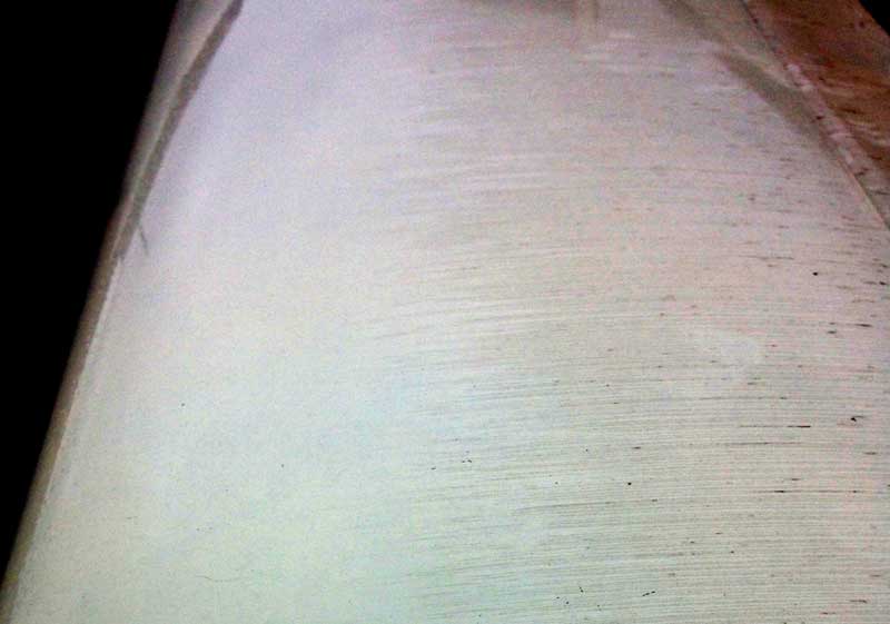
A couple of windstorms blew a lot of fine silty dust into the hangar, where it settled on the airplane. Today was showery, and I went flying in hope of getting some interesting streaks in the dust. I was lucky, in that there was enough rain to make streaks but not enough to wash the wings clean. After landing I took a number of pictures that reveal interesting details about the boundary layer flow. A few of them follow. The contrast has been exaggerated considerably to make the effects more visible; the airplane was not really covered with so much dirt that you could plant potatoes in it.
In the first picture, taken from the left wingtip looking toward the fuselage, the extent of laminar flow can be seen from the fact that the skin is clean from the leading edge back to around 40% of chord. This may not represent the true extent of laminar flow on the clean wing, however; the rain and dust themselves accelerate transition.
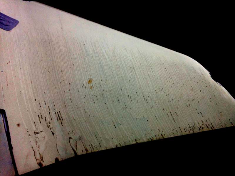
The next picture shows the right wingtip. The extent of laminar flow is much smaller, in part, at least, because leading edge sweep makes it more difficult to maintain. It's instructive that there is a pool of separated flow in the bend, where the pressure recoveries on the wing and the upturned tip form a mildly divergent channel.
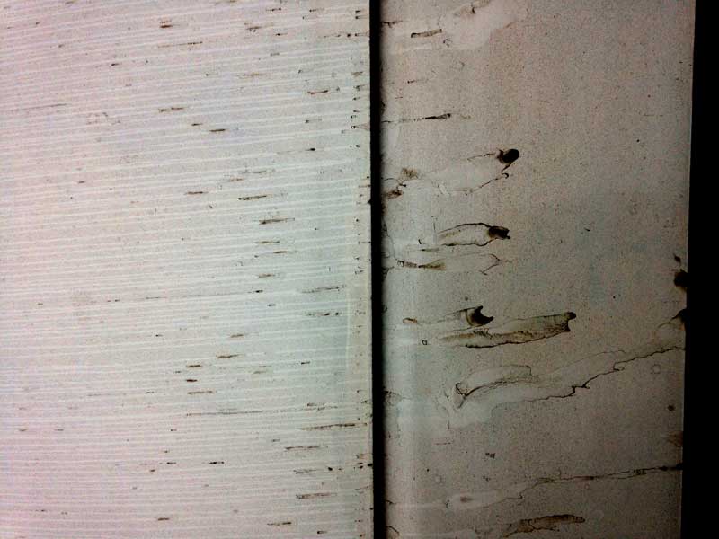
The third picture shows another area of dead air, this time the upper surface of the aileron. The boundary layer evidently thickens significantly, or separates entirely, aft of the gap.
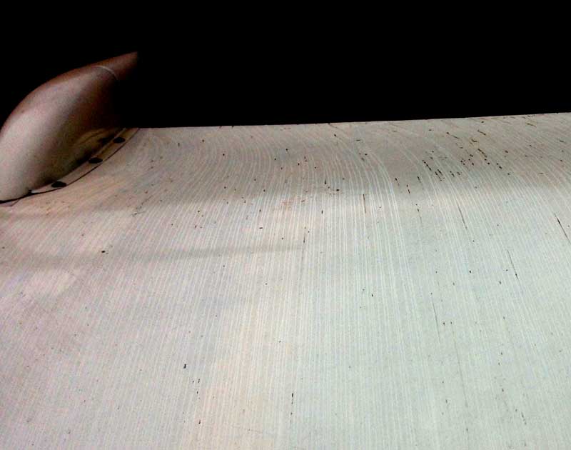
The next picture illustrates a curious phenomenon: spanwise flow near the trailing edge. The flow direction is inboard on the upper surface and outboard on the lower, and is related, I assume, to spillage at the tip and to formation of the tip vortex.
Finally, here is the flow around one of the flap track fairings. It's interesting that the flow does not hug the fairing, but seems to spread out away from it. There must be a pool of low-energy air close to the intersection. I don't know whether more of a fillet would improve the situation; I doubt it. In this picture, as in the first one, the transition from laminar to turbulent flow is visible.
[November 1, 2018]
It seems remarkable that this year had no October.
After making and breaking a number of appointments I finally got the propeller balanced per the recommendation of Art at Able Air back in June. I approached this operation skeptically, feeling that the idea that you ought to balance your prop every 500 hours was like the advice of shampoo manufacturers that you apply the stuff liberally and twice. But I tend to make the miser's assumption that everyone is out to swindle me. The traveling technician who performed the operation was named Leo Chrisostomo. Had I know this in advance I would have been even more suspicious, since the name, which means "golden-mouthed," suggests someone particularly persuasive and therefore potentially misleading. Leo connected a couple of what I thought looked like accelerometers, but he said were now called "velocimeters" (I think), to the front and back of the crankcase and had me run the engine at 1,700 and 2,000 rpm. An oscillograph made squiggly lines. Leo's expression suggested that he found the results a little startling. My engine, it seemed, was very far out of limits, registering 1.5 of some unit or other when the allowable value was 0.2. If this had been PSA, relatively speaking, I would be a goner. I was puzzled that the engine could be so far out of whack and yet feel so smooth, but he said it was all in the Lord mounts. Thanks be to thee, O Lord, as St. John Chrysostom probably used to say. He screwed a couple of weights onto the prop hub and we tried again; now the excess was merely half of what it had been. Another pair of weights and the engine was within limits, if just barely. We stopped there. I took the plane around the pattern and indeed it felt different -- silkier, as it were. Probably well worth the $300, especially if it prevents another alternator going to pieces on me.
After all the thinking about the flap position buzzer back in September, I decided to try the simplest of all options, namely a buzzer and a microswitch, nothing more, with the thought that in the time it takes me to react to the buzzer the flap will have continued past the microswitch anyway, and so there may be no need for additional ingenuity to keep it from buzzing interminably.
[September 14, 2018]
I dropped the plane at Able Air yesterday with trepidation, but Art called me a few hours later to report that the mag problem had simply been a plug "packed with carbon" on the #3 cylinder. Evidently my carbon-detecting skills are poor, since I had inspected all the plugs and not recognized this condition. I wish I had been there to see what it looked like. He suggested that I lean the mixture while taxiing, something that I know is desirable but have lazily neglected to do. The bill was $90, to my great relief.
[September 11, 2018]
A kindly correspondent pointed out that in original version of the circuit below the capacitor should have been in parallel with the Sonalert, not in series with it. Russ Hardwick was innocent of this error. It was sheer stupidity on my part, like thinking that you fill a bottle from the bottom and empty it from the top. I have now corrected the sketch.
[September 7, 2018]
Matters have been temporarily derailed by a 200-rpm drop on my right mag. I inspected all the plugs, found nothing remarkable, and put everything back together. No improvement. The shop I am currently annoying with my business, Able Air, can't look at the plane til next Thursday. Maybe that will encourage me to make some headway on the intercooler tanks.
Last week Russ Hardwick and I discussed how to design a circuit to produce a tone lasting one second or so any time the flap passes, or stops at, the takeoff position. I felt that I understood at the time, but now I have forgotten again. I think there's a microswitch or a reed switch, a relay, a capacitor and a Sonalert, and you just connect them in all possible ways, one after another, until you get the desired effect. Just kidding. Actually, I think this is the circuit. I just need to figure out the right size capacitor for the Sonalert. The behavior of the circuit relies on the capacitor filling up much faster than the relay actuates.
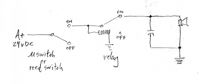
[August 15, 2018]
A simple audio tone to announce the arrival of the flap at the takeoff position would make it unnecessary to watch the flap going up or down.
[August 13, 2018]
I happened to see a professional test pilot's evaluation of a certain airplane whose flying qualities are generally admired. He roundly rejected it for a training role, judging a number of its traits UNACCEPTABLE. I began to think about how Melmoth 2 would fare under such unsparing scrutiny, and I concluded that there are many obvious faults which I had simply agreed with myself to overlook.
One is the way the flap operates. To raise or lower the flaps, you move the flap handle to the up or down position until reaching the desired flap setting, then re-center the handle. (The gear works the same way). The handle operates a cable loop that goes to a valve. It also carries a two-lobed cam that triggers a single microswitch to operate the hydraulic pump. There are, for practical purposes, only two flap settings, takeoff and landing. For takeoff, the flap extends aft but deflects only a few degrees, producing a large area increase but only a small change in drag and pitching moment. Because of the long distance traveled (15 inches at the wing root) the flap takes about 12 seconds to reach the takeoff setting. It takes only two more seconds to get to the full (30 degree) deflection. (You can see this here and here.) Because of the rapid increase in drag and pitching moment associated with flap deflection beyond the takeoff setting, the pilot's attention is diverted (most critically, while setting the flap to the takeoff position at the start of a landing approach) by the task of monitoring the flap travel. Also, after takeoff, while retracting the flap, I tend to watch it while waiting to shut off the hydraulic pump, even though it does no harm for the pump to run for a few seconds against its own bypass valve, which emits a faint but useful scream of protest. (I have an unfortunate tendency to anthropomorphize machines; for instance, I don't like to keep my computer waiting.)
Landing gear operation involves similar deflections of pilot attention, but for shorter periods; the gear cycles up in five seconds or so, and down in two.
Lying on my back on top of Mt. Wilson last night while watching the generally disappointing Perseid meteor shower (imagine the even greater disappointment of the fellow who installed a 100-inch telescope there, only to notice, too late, that Los Angeles was just below) I mulled over how to mitigate this situation. During the retraction cycle, I would like the hydraulic pump to automatically stop when the flap is fully retracted; during extension, I would like it to stop at the takeoff setting. But then what? The flap handle is already down. There could be a pushbutton next to the flap handle that would override the limit switch and let the flap run down to full deflection.
There is a problem implementing this seemingly simple arrangement, however. The same microswitch on the flap handle energizes the pump during both up and down cycles, so whatever happens on the trip down will happen on the trip back up. Do I want the flap to stop at the takeoff setting when I'm trying to retract it? Well, maybe yes. For a go-around, for instance, that would be desirable.
But there is a bigger problem. At present there exists a clear, unvarying relationship between the position of the flap or gear handle and the state of the hydraulic pump. But once you add "logic" to the system, in the form of a second microswitch overriding the first, you introduce weird new possibilities. For instance, suppose the flap handle is down, the flap is at the takeoff setting and that limit switch has turned the pump off. Now I lower the landing gear. The gear handle microswitch now energizes the pump; fluid goes to the gear and to the flap as well (because the handle is down), the flap moves past the limit switch and runs down to full. Or the inverse would occur if the flap handle were up. Either effect would be highly undesirable and potentially hazardous.
There are certainly ways around such difficulties, but they involve increasing complications, make the system harder to understand, and create new modes of failure. Maybe a better approach would be to not let any professional test pilots evaluate the airplane.
[July 31, 2018]
I have accomplished nothing at all lately. Most days have been sucked up by writing, kid transportation or hot-weather laziness. When an empty day presents itself Nancy and I drive up to Ojai to help our son Nick with his house, into which his family intends to move in less than three weeks. Nick and I did fly down to Jacumba, on the Mexican border, on the 20th, to look at his '68 Malibu, which is being refreshed there like Aphrodite at Paphos. The trip down was a bit crawly, but on the way back we had a 20-knot tailwind at 12,500 feet, it was very clear and smooth, and we crossed right over the top of the LAX Class B and had a long fast dive to Santa Paula, where Nick had left a car. A long time ago I wrote about the pleasure of descending from 20,000 feet in Melmoth 1 and seeing 220 knots on the DME while listening to a favorite piece of music, and I mused about whether the pleasure might have been further increased had I had a slice of sachertorte to eat at that moment. I have since concluded that pleasures do not always add arithmetically, but sometimes tend to subtract from one another.
Jacumba is an odd little place. There are hot springs there, and our friend said that it used to be a resort of Hollywood types, like, say, Two Bunch Palms in "The Player". The recently paved 2,500-foot runway is right next to the border fence, a not especially forbidding-looking palisade through which a sufficiently svelte person could probably slip without much difficulty. It would be still easier, however, just to stoll over to the 1,000-foot gap about half a mile east of the runway, which would give the Clown in Chief a well-deserved conniption.
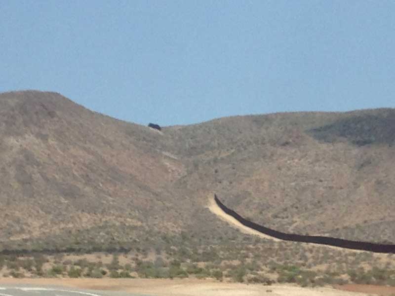
[July 3, 2018]
Late in June I sent away an oil sample for spectroscopic analysis. The last time I did this was in 2003, shortly after Melmoth 2 began flying. It's interesting to compare the results from two analyses 15 years apart. With the sole exception of copper, which went from 4 ppm to 6, all of the wear metals are present in lower concentrations now than when the engine came out of 20 years of storage. Aluminum went from 12 ppm to 2, Iron from 53 to 37, Nickel from 7 to 6 and chrome from 3 to 2. The engine now has 1,800 hours. At this rate it will soon cease to wear altogether, except for its copper parts. The oil analysis firm does not provide tolerances, except implicitly, through the use of decimal digits, which I have rounded for the sake of simplicity. But it says that all values appear normal. That was a relief.
[June 23, 2018]
In case anyone is interested in this sort of thing, the so-called "tanks" that conduct air into and out of the intercooler have to sustain an internal pressure equal to the maximum boost, as well as, on the inlet side, a temperature of around 250 deg. F. So part of the design process is to decide what "maximum boost" is going to be. If I wanted to be able to get 41 inches at FL180, where the ambient pressure is about 15 in. Hg, max boost would be 26 in. Hg and the pressure would be (26/29.92) *14.7, or about 12.8 psi. Realistically, however, I think I would be satisfied with 30 inches at 18,000 feet, which would provide 75% power. Being more frugal than impatient, I never use even that much anyway. So, (15/29.92) *14.7 = 7.4 psi. The area of the intercooler face is about 47 sq. in., so we get 348 pounds of pressure trying to blow the tanks off the intercooler.
[June 19, 2018]
The latest on the alternator coupler is that it is both a vibration damper and a shearable link. So much for that.
I put the alternator back into the plane on Saturday. I had a hard time with the transverse exhaust pipe, which passes behind the alternator and has to be removed to allow the alternator to come out. The pipe, which has the heater shroud wrapped around it, is straight, with a tapered flange at each end; the mating parts also have flanges, and these flanges are drawn tightly against gaskets by circular clamps with a V-shaped cross-section. The pipe looks as though it ought to be able to be put in either way, but actually the flanges on the two ends are of different types, one thicker than the other, and the flanges on the mating parts are as well. It turns out that you have to mix, not match, to get the clamps to work; if you put the two thicker flanges together, the V-groove can't handle them. I suppose I may have known that once, but if I did, I forgot it, and it took me about half an hour, and some bloodshed, to figure it out anew. Once I got everything back together, the alternator checked out fine on a runup.
I then decided to do an oil change, and to get a spectroscopic oil analysis while I'm at it, something -- the analysis, not the oil change -- I haven't done for 15 years or so. Things went fairly smoothly this time, since after last time's flood I wrote "Aft end" at one end of the trough that conveys the used oil into the bucket.
[June 15, 2018]
My supposition about the function of the wildly expensive coupling between the alternator and its driving gear was apparently incorrect. According to the technician at Aero Accessories from whom I picked up the overhauled alternator this morning, it's just a plastic connection designed to avoid dropping metal fragments into the engine in case the link fails. That makes it even harder to understand why TC asks $1,500 for the thing. But I wonder whether he's right. In any case, he said that failure of the outer case of the alternator is something they see maybe once a year. He assumed it was due to vibration wearing the aluminum threads, so that the steel bolts and safety wire all remain intact, but the whole structure comes loose.
[June 12, 2018]
Lacking a belt to damp the torsional vibrations of the engine, the direct-drive alternator requires a flexible coupling between its shaft and the gear that engages the accessory drive. After some number of hours of use, this coupling wears out. It is no longer possible to secure it to the alternator shaft with the required torque, and it must be replaced. This was the case with mine. Unfortunately, the diminutive item comes new from Continental for a cool $1,500. Reconditioned, they're $575 from AC Spruce. I think I've found one for $350, but it remains to be seen whether it will pass the torque test. This experience has reminded me that I am not really in the airplane owner demographic, and my flying career will last only as long as not too many expensive parts of my plane break at once.
[June 6, 2018]
I took the plane to Able Air this morning. The problem with the alternator turned out to be the alternator. In the seven years since I installed t, it had shaken itself to pieces. This is a little hard to understand, because the engine is quite smooth and I feel that the vibration level in the plane as a whole is low, but, as the mechanic said, you can never tell about vibration. Tomorrow I will take it to Aero Accessories at Van Nuys, where I bought it in 2011, for repair. What was surprising, and instructive, about this was that I had inspected the alternator before taking the airplane to the mechanic, and noticed nothing; but my attention was directed to the wire connections, and since the alternator itself was ostensibly intact, with all its bolts and screws and safety wire in place, it never occurred to me to grab the end of it and shake it to see whether it was coming loose from the rest.
The mechanic asked when I had last had my prop balanced. Forty years ago, I said. He suggested that every 500 hours would be a better interval.
[June 2, 2018]
I took off for Paso Robles this morning to attend the annual Antique Aero barbecue, but turned back after 20 minutes with the ammeter indicating a continuous five-amp discharge and the voltage meter just 24 volts. I've seen flakey behavior in the charging system before, including on the previous flight, but always the system would pull itself together after a few minutes and do the expected thing, that is, initially indicate a charge as the battery recovers from starting the engine, then gradually drop to zero charge or close to it and maintain a steady 28 volts. I made an appointment with Able Air (where I used to hangar Melmoth 1 in the Bob Eeg days) to troubleshoot the system on Wednesday.
I tested my old epoxy a few days ago; it's still good. I don't have much graphite cloth, however; I have to decide whether to settle for glass or spend some money. I'm tempted to use glass just because it's so much more cooperative. Graphite is so stiff, it's a pain on small radii like these. Maybe I can use a little of each; that would seem high-tech.
[May 25, 2018]
The intercooler inlet and outlet tank molds are ready for laminating. I need to find out whether my out-of-date high temperature epoxy will still harden, and whether I have enough carbon cloth for the parts (I suppose I could use glass; it's a question of stiffness, not strength, and so carbon would be preferable). More important, I need to figure out how to split the parts in order to be able to get them free of the molds. The molds represent the inner surface of the parts; in other words, the parts themselves will be laid up over these molds.
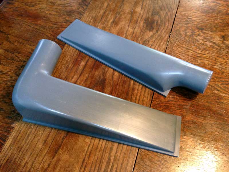
[May 14, 2018]
When I am thinking about the airplane here at home, I often refer to photographs to refresh my memory of the arrangement of certain details, particularly ones inside the cowling. This morning I began to reflect that the ambient pressure source for the injectors and mags -- both of which are pressurized by the turbocharger -- and possibly also for the manifold pressure gauge, is a tap in the duct leading into the throttle body, and that this tap is at a right angle to the flow direction. Since the flow speed in that duct is around 100 mph, there might be some pressure drop, and so I may not be getting full pressure. I consulted my photos and found, first of all, that I was wrong about the MP source; it comes from the crotch of the Y downstream of the throttle body. At least I think it does; actually, every one of my photos manages to hide that area, which resembles the pudendum of a putto, as modestly as those fortuitous bits of foliage and fabric in paintings of yore do the corresponding parts of Venus, Mars or Jesus. But it stands to reason that the MP pickoff would be downstream of the throttle; I was silly to think otherwise, however briefly. At any rate, I shall go to the airport today and visit the scene in person. Fortunately, my manifold pressure gauge has two needles, one of which tracks ambient pressure and provides, for anyone who can subtract, a crude but reliable backup altimeter. I can temporarily hook that one up to the pressure tap that goes to the mags and injectors; the two needles will show the pressure drop, if any.
[April 12, 2018]
The story of the Lowrance GPS continues, and never fails to amuse and astonish. The last time I reported on its behavior, in December, I had replaced its internal battery and it was now remembering to send position data to the autopilot; but it had stopped offering airports, NDBs and such stuff as Go To options, and was confining itself to waypoints, of which, incidentally, none were programmed. In addition, its map would display road, airport, position and track data, but not airspace boundaries. I was pretty well resigned to this state of affairs when one day it suddenly remembered its airports and NDBs. Then it would not search properly; it would go up to about the middle of the alphabet and then jump back to the beginning. After a couple of restarts, however, it abandoned that annoying behavior and acknowledged the entire alphabet. A couple of flights later, airspace boundaries suddenly appeared. It was like a stroke victim slowly relearning how to speak and walk. I do not know enough about electronics to understand how a device like this, which must have about the neurological complexity of C. elegans, can behave so capriciously, but I am glad to see that its fundamental impulses still exist, and are sound.
[March 28, 2018]
The ghostly lineaments in the previous entry are taking (as yet unfinished) form as wooden molds. The intercooler tanks will be laid up, using carbon fiber, over these molds. The one on the left is the inlet.
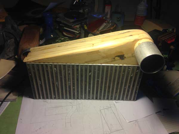
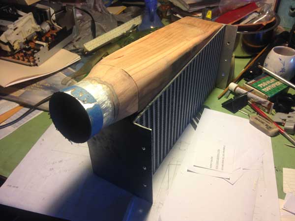
A kindly reader expressed concern about my long silence. Actually, I am well and so is the airplane. (The nation, maybe not so much.) I have done very little work on the plane lately, for several reasons. One is simply that I am in a period of slackened interest in working on it; my interest in various projects -- improvements on the airplane, repairs on my son's newly purchased house in Ojai, adding capabilities to my lofting/CFD software, translating a German memoir of my father's and editing another, working on a Melmoth 1 memoir of my own, and of course the usual article-writing and its attendant research -- rises and falls, and at the moment a lot of my free time is going into trips to Ojai and the translating and editing work. Plus, although I feel I am getting closer to the correct solution, I am still uncertain about some details of the intercooler plumbing. I am pretty sure, at least, that I have the position right. Here is the palimpsest upon which my runes are inscribed:
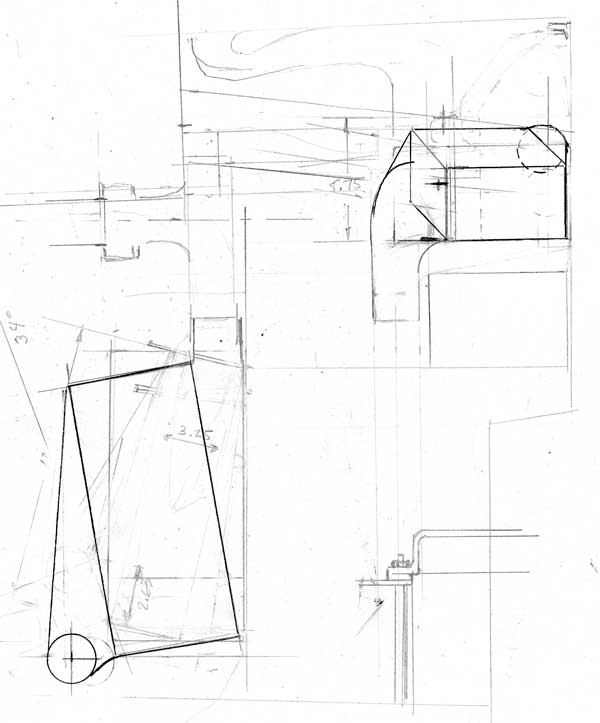
I do not expect this to be comprehensible; I am including it just to show that I do occasionally pick up a pencil or, more often, an eraser, and inflict something upon a piece of paper. The process has been somewhat impeded by my stupid choice of some redwood that happened to be lying around here as the material from which to make molds for the two high-pressure "tanks" that bring air into the intercooler and conduct it thence to the throttle body. Redwood is a material of constantly varying density, and singularly ill suited to mold-making. However, once I have made a mistake I am determined to persist in it. I am pretty satisfied with the inlet and outlet paths for the induction air, although the very tight 90-degree turn to the throttle worries me a bit, just in terms of its effect on flow distribution in the log manifolds. The cooling air is a different story, but it, at least, I can defer thinking about until a later time.
[February 14, 2018]
I tried a different position for the intercooler, and I think it's better. The inlet path for cooling air is less obstructed, and the paths for the charge air both into the cooler and from the cooler to the throttle body (identifiable as an orange sleeve in the photo) are better aligned. But I am still waffling about the whole idea, in part because of the weight of the intercooler itself -- around six pounds. I think it's bigger than it needs to be. Someone cautioned me against sawing off one end of it, but I don't know what difference it would make if I did so and just bonded a new end plate to it with a mess of JB Weld. At any rate, the non-airplane aspects of my life have been more than usually complicated lately, and I've spent less time than usual on the plane. So between lack of time and uncertain motivation, the intercooler is making no headway at all.
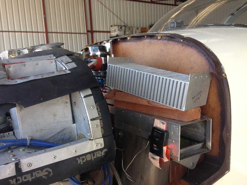
[January 28, 2018]
Moving at a more than usually glacial pace, I mocked up the intercooler placement, using wood wedges in lieu of the eventual "tanks". I don't like the arrangement, now that I've seen it, and am going to try a different one, with the large face of the core horizontal rather than vertical.
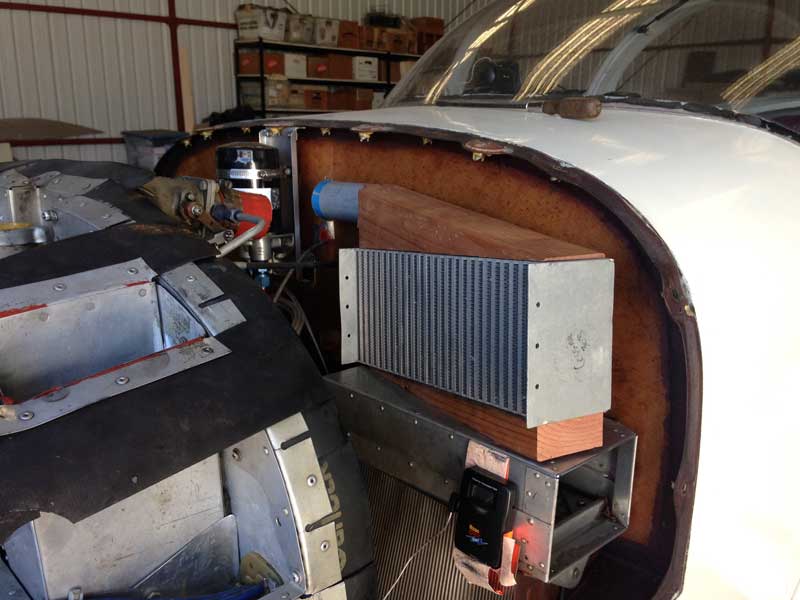
After writing an Aftermath column in which the cause of the crash was the pilot's faulty handling of an aborted landing, I became curious about whether Melmoth 2 could climb with full flap and airbrake -- one of many things that I have never tested. I tried it, and found that at 70 kias I could climb at several hundred feet a minute at 26/2800, which is nowhere near full power. (The airplane was extremely light, however.) The only problem was heating; the CHTs rose rapidly because of the low airspeed. The proper technique for a go-around would be to maintain level flight initially while cleaning up and accelerating. The pitch changes with airbrake and flap retraction are quite marked, but easily managed if you're prepared for them.
[December 30, 2017]
I collected some temperature readings in the duct leading into the oil cooler, with and without the deflector. The temperatures were, on average, 20 degrees F above ambient with the deflector and 30 above without. This suggests that maybe I ought to look into making up some sort of duct that runs directly from the peripheral intake to the oil cooler; at present the oil cooler duct takes in a mixture of deflected cold air from the peripheral duct and warm air from the plenum. Incidentally, these data were collected while cruising at 4,500 feet at 144 ktas on 6.8 gph -- another example of the airplane doing better than expected at very low power settings -- 25/2100 and way LOP, in this case.
Today the unpredictable #1 Lowrance worked, to some extent. Now that I have replaced its internal battery, it remembers that it is supposed to be producing NMEA output for the autopilot coupler. On the other hand, it seems to have forgotten its airport and navaid data, and now offers only user waypoints in response to the "Goto" command. I suppose it would not be that much trouble to program the waypoints I use most often. But would it remember them?
[December 2, 2017]
On the theory that air directed along the bottom inner surface of the cowling by the splitters I installed in the inlet might be sticking to the surface for Coanda-like reasons and not getting into the oil cooler inlet duct, I installed an aluminum deflector on the floor of the plenum in such a way that it would steer this putative river of cold air into the duct. The first time I tested it in flight I got the impression that it had had a remarkable effect; but as time went on the effect appeared to vanish. The only way I will know for certain is by measuring the temperature in the duct with and without the deflector in place.
My seemingly successful installation of a new battery in the #1 Lowrance has resulted in a unit that remembers its settings, but refuses to lock onto a satellite, even though it passes its self-tests okay. Meanwhile, the #2 unit, which is currently installed in the airplane, has developed a new problem: it remains on for only a few seconds after startup, and then turns off. I suppose it is foolish of me -- perhaps I am a deranged US dotard -- to suppose that electronic devices almost 20 years old can be expected to function normally.
[November 19, 2017]
Here's another plot of the same data, this time temperature rise versus net boost pressure above (or below) ambient. Different altitudes produce scatter, but on the whole the points line up fairly well.
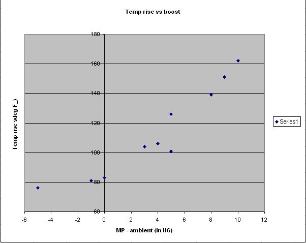
[November 18, 2017]
Yesterday I collected some baseline data that will allow me, at some future time, to assess the effectiveness of the putative intercooler. I recorded induction air temperature at 20, 25 and 30 in. Hg at 4,000, 8,000, 12,000 and 14,000 feet. I had intended to finish the series at 16,000 feet, but it became apparent that the temperatures were getting quite high and I did not want to venture past 200 deg. F.
Here are the data I collected:
The left-hand chart is simply the right-hand chart minus the OAT.
The astute viewer will wonder why the temperature rise is so large even at low manifold pressure and low altitude, where no compression at all should be taking place. The reason is the peculiar design of the Piper "fixed wastegate" system that I have modified to incorporate a manually adjustable wastegate. The bypass is only 3/4" in diameter, and so even at low power a significant amount of exhaust gas is going through the blower, which is pumping against a partially closed throttle. This is an inefficient arrangement, obviously, but by using low rpm (these tests were run at 2,300 rpm, but I often go lower) I can open the throttle fully at 8,000 feet or so. I seldom cruise lower than that -- more usually above 10,000 feet. It's evident, anyway, that there's a good deal of heat to be gotten rid of.
One question on my mind was whether I needed to provide a separate cold air intake for the intercooler, rather than use the air already in the "cold" plenum. The temperature near the firewall is about 45 deg F above ambient -- this due to heating by the exhaust pipes and the turbocharger. Assuming 50% efficiency (I think this is the wrong term; it should be 'effectiveness'; but it's the one they use, and simply means the temperature drop across the intercooler divided by the temperature difference between the charge air and the ambient air), that would mean 22 degrees less temperature reduction if cowl air were used. But it might be worth a try, nevertheless.
[November 16, 2017]
Goaded by Peter Lert, I broke the solder joints to the dead battery in the Lowrance and extracted it, a 3v Renata CR2450N valued at $2. Following his advice, I crammed a new battery in with padding to press the contacts against it, and voila, it remembers! But -- can it be TSO'd?
[November 15, 2017]
My design process has always involved obsessively thinking about the object to be designed. I remember, during the construction of Melmoth 1, intensely visualizing the retraction linkage for the main landing gear while meditating at the Cimarron Zen Center of Rinzai-ji. How, I pondered, is the gear koan to work? I am now at the same stage with the intercooler. My recollection of the details of the engine compartment is not so complete or exact that I can mentally map every attachment and duct path, but I have dozens of photographs of it to help me. A number of criteria must be met. The intercooler must be able to be built piecemeal, without having to ground the airplane for long at any stage. It must be easy to remove, with as few attachment points as possible, and have short, direct flow paths. It must require moving or damaging as few existing items as possible. My mental scheme is like a rapidly oscillating object that at first appears blurred, but, as it slows, acquires sharper outlines and at last halts in place.
The most suitable location for the heat exchanger seems to be on top of the present induction air box, rotated so that the aft inboard corner touches the firewall while the aft outboard edge is about an inch and a half from it. The firewall thus forms the roof of the wedge-shaped "tank" that feeds cooling air into the core. On the opposite side, a similar tank (for that is the name of the end housings through which air enters and leaves), also deepest at its outboard end, collects the heated air into a 3-inch SCAT hose that discharges forward into the upper plenum. A third tank, on the bottom surface of the core between it and the induction air box, is connected to the existing riser coming from the turbocharger; on top of the core, a fourth tank feeds the cooled air to the throttle. In this arrangement, the intercooler is attached to the airframe, not the engine, and three flexible segments are required to join it to the engine. (I am reluctant to attach such a large, relatively massive object to the engine.) I have not yet found out how much cooling air the intercooler requires. A turbonormalized Bonanza has a ram air intake about 3 or 3.5 inches in diameter, but unless the velocity ratio in the duct happens to be 1.0, that tells me little about the actual mass flow. I had thought about constructing a pitot-style inlet with a boundary layer channel, but I decided it would be rather complicated and possibly draggy, so my present thought is to replace the existing NACA scoop in the cowling side panel with one about three times larger. This would supply both induction and charge cooling air. I'm not sure what the politics of splitting the inner channel of a NACA scoop are, but I'll find out. The most difficult part of the whole project, I think, will be making the induction-air tanks, which have to withstand both heat and pressure.
In the meantime I attempted to break into one of my Lowrance GPSs, having learned from the company that they no longer support such ancient devices as mine. There are no external screws on the case, which seemed to be glued shut. I cracked the joint with a chisel and pulled the halves apart sufficiently to see the battery that maintains the device's memory. Unfortunately, it is soldered to the circuit board, and so there is no practical way to replace it.
Incidentally, Monday, 11/13/17, was the last day, until almost 90 years hence, whose date is written (in the US, at least) as three successive primes.
[November 8, 2017]
I talked with someone who knows something about intercoolers. The guidance I came away with was that 1) I should not try sawing off the end of an intercooler core; 2) small differences in size are not critical, since the original choice of a size was probably based on false assumptions in the first place; and 3) the cooling air flow requirement is about what fits in a 3-inch SCAT hose. Ah, the cool, fresh air of simplification!
[November 6, 2017]
The puzzle of the failure of the autopilot to couple to the GPS is solved. The problem seems to have been related to the Lowrance's having lost the memory that restored its previous state at each startup. One of the settings that were being lost on each shutdown was "NMEA On" -- that is, the command to send course deviation information to the autopilot. If I reset that selection on startup, the system works as expected. The failed memory is presumably sustained by an internal battery, and that battery has evidently lost its ability to hold a charge. I assume there is a way to replace it, but so far I have not even figured out how to split the case. I will.
My vague plan to install an intercooler has advanced to the point that I have more or less decided where it will go. The next step is to find out whether I can make one of the heat exchangers that I have smaller by sawing off one end of it. I have three cores, one of which was originally intended for a 250-hp engine, one for a 310-hp, and the third for a 72-hp McCulloch two-stroke. Obviously, the last is too small, so forget about it. The others are too big, and for reasons of weight, space and internal resistance it is probably not desirable to have excess intercooling capacity. At any rate, I need to figure out how big an intercooler is appropriate and what volume of cooling air it will require. Probably the 250-hp one (for example) was sized for 75% power at the critical altitude, say 18,000 feet. I never fly at 75% power (except for takeoff), but I suppose the airplane should be capable of meeting the needs of some other pilot, since it is likely to live longer than I. I have not located any strict rules for sizing intercoolers, so for the time being I am supposing that I would use 80% of the 250-hp one or 65% of the 310-hp one.
[October 11, 2017]
The borescope did not find anything obviously wrong with the #4 cylinder. It did make a nice portrait of the top ring gap reflected in the polished cylinder wall:
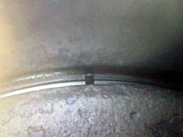
I ran the engine for a few minutes and then checked the compression of the #4 cylinder again. Now it was 72/80 rather than 40/80. I thought that 40 didn't seem likely.
[October 10, 2017]
At the end of the eclipse trip, which involved about eight hours of flying, there was a fine mist of oil on the right side of the windscreen, enough that I could not see clearly through it. The oil consumption had not been out of the ordinary -- about one quart in 10 hours. It was evident from that, and from the fact that the mist had not coalesced into large droplets or streaks, that the amount involved was small, but evidently from some new source, since I had not seen this problem before. I was thinking that I would carefully clean the right side of the engine and then check it after each flight to locate the leak; but it was became clear, as soon as I removed the cowling today -- various things had prevented me from getting to it sooner, though I had flown in the meantime -- that the leak was coming from loose joints in an elbow in the 3/4" pipe that conducts air from the oil separator overboard. Lengths of aluminum tubing were simpy slipped into the elbow without any kind of positive seal, because I had thought there would be very little pressure in that line. I now contemplated cutting O-ring grooves in the elbow, but settled for gluing the tubes into it with red silicone. I then did a compression check (for the first time since January, 2014 -- "If it ain't broke..."), and found that the #4 cylinder was holding only 40/80. This seemed odd, since the others were still in the mid-70's and one was 80/80. I suspect that there may be some little speck of carbon or something under a valve, and that if I fly and then check the cylinder again I will find it in line with the others. In the meantime, however, I will examine it with the digital borescope that I got some while ago for $18, and have never yet found an excuse to use.
I had the Porcine Smart Coupler benched checked by its maker, and he reported that it is okay, which, he said, was too bad in a way, because troubleshooting the rest of the system will be more difficult. I may have to give up the Lowrance GPS, whose behavior has grown increasingly flaky, and replace it with something newer. Unfortunately, the iPad, which provides a beautiful navigational display, does not provide the digital output required to link it to the autopilot.
In the meantime I have been toying with the idea of installing an intercooler. I have toyed with this idea before, but never gotten past the toying stage. I have several intercoolers lying around, none of which will be suitable for my 200-hp engine without modification. I don't think I have any practical need for an intercooler -- I seldom go above 14,500 feet -- but I would do it, if I do it, just to round out the tubosystem.
[September 25, 2017]
A highly compressed video of the eclipse trip is here.
[August 23, 2017]
The curious pattern of light on the instrument panel -- and everything else in the cabin -- was, I think, a schlieren image of density variations in the plexiglas of the canopy.
[August 22, 2017]
The universe was kind enough to schedule a solar eclipse on my birthday, so on the 20th my son Nick and I flew up to Winnemucca, Nevada, where we spent the night before continuing to above Weiser, Idaho. There we observed, or perhaps a better word is experienced, the event from a perch at 14,000 feet.
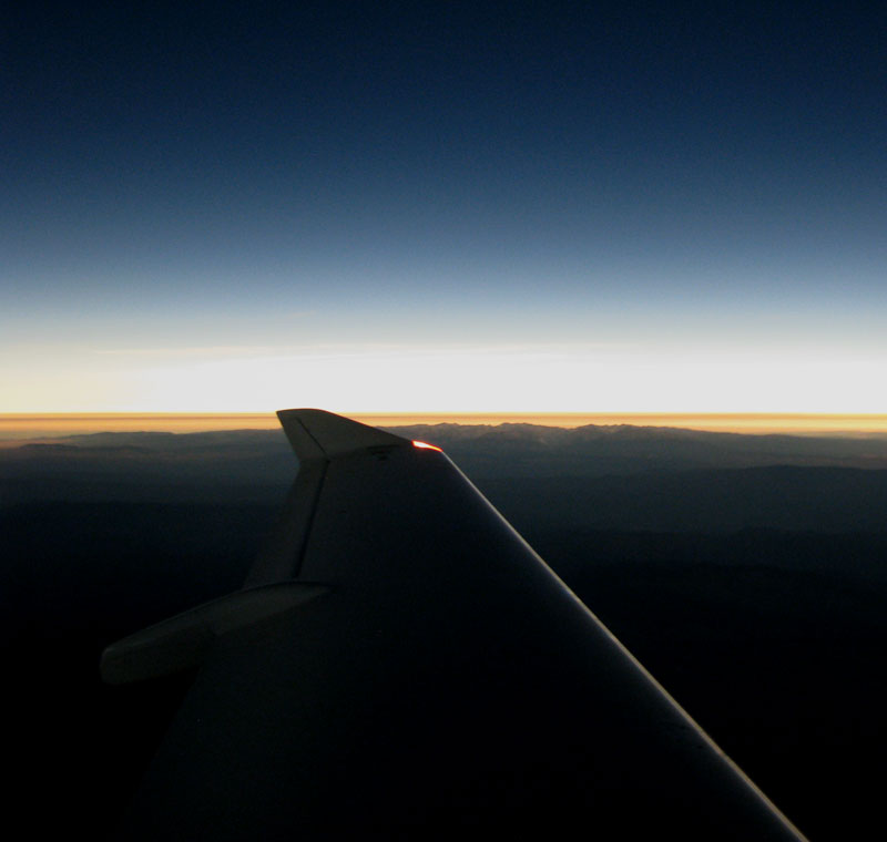
Enough has been written about this eclipse that I will not add my two cents, except, first, to explain that the tawny line along the horizon in the photo above, taken at 11:26 a.m. MDT from the middle of the umbra, was due to smoke from fires in Oregon, and, second, to note a curious optical phenomenon whose cause I do not know. I suppose it must have something to do with the plexiglas canopy, but for some reason the only time I have ever seen it was just before and after totality in this eclipse. All surfaces appeared pebbly or rumpled. The paper on my kneepad looked as if it had been soaked in water and then dried, and the instrument panel resembled the surface of a hilly, eroded landscape.
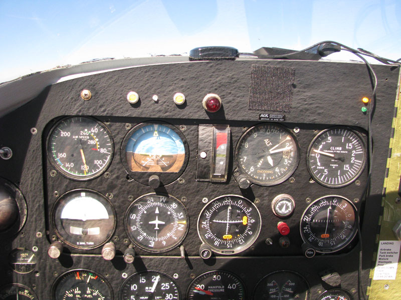
[August 14, 2017]
The house work goes on, but on Saturday I woke up early and slipped away to the airport. I was obsessed with wondering whether there was a way to get the leaky nosewheel hydraulic cylinder out of the airplane wihtout having to dismantle everything surrounding it, which requires jacking the airplane and is a big pain in the neck. The freeway was conveniently empty, the airport dim and silent. I quickly found that yes indeed, there was a way; and in ten minutes the cylinder was out. I opened it up and inspected the O rings; everything appeared okay. I left it on the workbench for further inspection. As I was leaving the airport I heard a plane heading down the runway, and I glimpsed it as it began to climb out. It was an airplane I always see parked, but had never before seen move: a Scottish Aviation Bulldog, quite a rarity in the US.
[August 8, 2017]
I flew today for the first time since June 27. I have been completely absorbed in house repairs, but they are finally coming to an end. I went up to Tehachapi, a bit less that half an hour away, where Mike Melvill has his hangar. I circled overhead but did not see his car; he is probably not yet back from Oshkosh and from visiting friends in Indiana, where he and Sally lived before they came to Mojave to join the then nascent Rutan Aircraft Factory. The Smart Coupler is still not working in spite of my having repaired a broken wire. On approach to Whiteman I found that the flaps would not work -- obviously low hydraulic fluid again, and on inspecting the usual leak sites I found that the nose gear hydraulic cylinder, which I thought I had repaired early in May, is again leaking copiously. I hope I can figure out a way to take it out without having to dismantle the entire nose gear retraction linkage again. This time the leak appears to be between the outer tube and the piston-end cap; last time I thought it was around the piston itself.
The one repaired thing that worked properly was the #2 radio.
[June 28, 2017]
It didn't take long to discover that the cause of the failure of the GPS to talk to the autopilot coupler was nothing more complicated than a broken wire. I fixed that. I then pulled the #2 comm radio, which I took home. Removing the fascia, I found that the plastic shaft connecting the Store/Select/Recall knob to its internal switch had failed where a shallow groove had been cut into it for a snap ring. Going by feel, I put, or at least I hope I put, the switch into the "Select" position, where it will henceforth remain. Another plastic knob, the tiny one that controls volume and squelch on the #1 comm, turned out to be cracked. I'll find a replacement for it.
[June 27, 2017]
I flew to Oakland yesterday, and there encountered an instance of the often forgotten fact that every feature entails a vulnerability. My comm radios are Collins Micro-Line dating back to 1975 or so. They're great radios and I have no complaint about them at all. One of their features, which was novel at the time (I think) but has since become standard, is a "Store-Select-Recall" switch that allows you to store a frequency for future use or to "remember" the current Center frequency before switching to the next one en route. In my radios, this is a rotary switch, and when I turned it something broke, leaving the radio in "Recall" mode and therefore incapable of selecting a frequency.
One interesting data point was that after climbing to 10,500 feet and cruising for a while, I decided to re-adjust the mixture. As usual I was running lean of peak, and I found that I had to enrich by 250 deg. F. to get to peak. So I now know that the engine will run smoothly at 250 LOP.
With reference to the June 16 entry regarding whether the iPad can talk to the Porcine Smart Coupler, which seems to be on the outs with the Lowrance GPS, as far as I can tell from discussions on line neither Apple nor ForeFlight provides an output of NMEA data to the autopilot coupler.
[June 16, 2017]
We returned on the 13th from Cape Cod, where we ended a trip that began in Mid-may with Nancy's 50th college reunion in South Hadley, Massachusetts. This was a three-day affair during which I met, among other people, a woman whose father, Charles d'Olive, scored five victories in Spads in World War I. Too late, sadly, to relate the encounter to my friend Javier Arango, who would have been delighted by it.
I flew for half an hour today after replacing my antediluvian Lowrance GPS with the spare that I got for $40 on eBay 18 months ago. I had been having two problems with the unit. One was that it often had to be restarted several times before it would show a complete map; initially it would leave out stuff like the boundaries of Class B or C airspace. The other was that it had stopped talking to the gadget that converts GPS course deviation information into autopilot commands. The replacement unit, once it had figured out that we were not in Tulsa, resolved the first problem but not the second. The second, however, is the more important, since the iPad provides a Technicolor map six times larger than the Lowrance's black and white one, but no autopilot output (at least that I know of).
[May 4, 2017]
Before leaving for the East on April 14, I overhauled my leaking left brake master cylinder. On returning, and after due delay for getting my affairs in order, I took the nosegear retraction apparatus out in order to fix a leaking hydraulic cylinder. While I was at it, I changed the oil. A couple of months ago I had made a permanent version of the temporary gutter that I hit upon in July, 2014 as a way to drain the oil without making a huge mess. Unfortunately, there are two ways to install it, and in obedience to Murphy's Law I unreflectingly picked the wrong one, with the result that two quarts of oil went into the bucket and six went onto the floor. Luckily I had a tub full of absorbent stuff, basically kitty litter I think, left over from the big fuel spill of January, 2015, as well as a pile of old clothes, sheets and towels that I had husbanded against just such an eventuality, and I was able to stanch the Stygian flood before it had advanced more than a few feet in several directions. The nose gear hydraulic cylinder turned out to have a prolapsed O-ring. I got everything put back together and cycled the gear today; no time to fly, however.
[April 12, 2017]
The iPad installation turned out quite well. On the first outing, it was free of reflections and perfectly visible as long as I did not look at it through my polarizing sunglasses, which make it appear completely dark. It's simply hanging from a hook and supported by one short leg, and can be removed as easily as a coat hanger from a rack.
I was taking a couple of visitors up for a short flight at the end of which the flaps would not go down. It turned out that the hydraulic fluid was exhausted, having leaked out of the nose gear auxiliary cylinder that I noticed dripping the other day. Fixing that will probably be a couple of days' work -- it will involve removing and replacing the whole nose gear retraction apparatus -- and I won't do it until we return from the East toward the end of April. Today, however, I did overhaul a leaking brake cylinder, apparently successfully. At a certain point there was a terrific racket outside the hangar; someone was running up a Stearman that appears, for the moment at least, to be my new neighbor.
[April 6, 2017]
In 1974, Gary Maker was a private pilot, an airplane enthusiast and a Flying reader. He lived in the San Fernando Valley, and one day was at Whiteman Airport -- "back when a person could just drive back there and watch the planes" -- where he saw the then much-publicized Melmoth 1 and snapped a picture of it. A few weeks ago he sent me this:
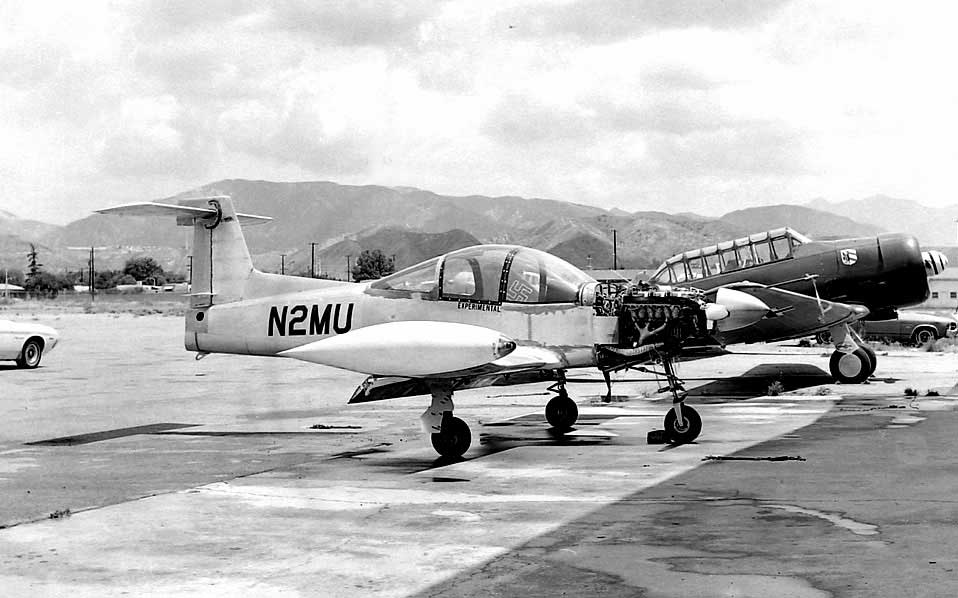
At that point the T tail and rear window mods had been done and the airplane was still unpainted. To judge from the clouds and the fact that the ground looks wet, this might have been taken in the late spring, but it appears to be of the same general vintage as another photo that was sent to me by Gino Barabani, and that has been in the "Melmoth 1, mostly pictures" section of this website for some time:
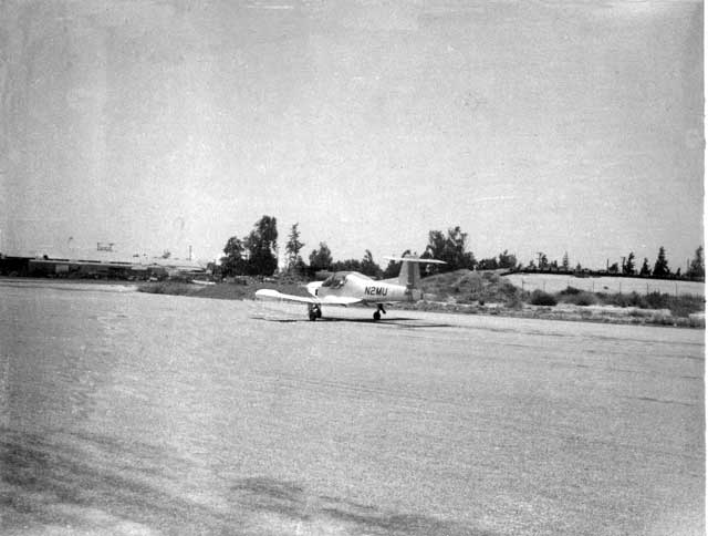
Recently Barabani wrote to me, "The date of this photo was 7-9-1974, it was a Tuesday. I flew my second solo cross country from Rialto to Whiteman Field in a Cherokee PA-128-140 N7303F just to see your aircraft. I read every article in Flying about your aircraft. This high school kid had to find out what kind of person could design and build their own aircraft, so I talked my flight instructor into letting me go to Whiteman field for my solo cross country. How sad that you where taxiing out just as I had arrived. The picture was taken with an old Polaroid camera; after the black and white picture was developed I had to run a clear liquid stick over the photo, so I never saw where you went."
[April 5, 2017]
I finally completed the iPad mount that I started thinking about in January. It looks good, but it remains to be seen how visible it will be; the transparent canopy is a powerful creator of reflections.
After landing the other day I noticed hydraulic fluid leaking -- what else is new? -- from the shaft O-ring on the small booster cylinder that is supposed to help the nosewheel along. I wonder whether that can be related in any way to the adjustment I made to get the nosewheel doors to close flush. It's hard to see how the two could be connected, since the leak is occurring when the gear is down, not up. At any rate, the change made the gas spring collide with the retracting arm, and so I have to revise the gas spring mount, which will require removing a bunch of stuff including the hydraulic actuator. I'll overhaul it then.
[April 3, 2017]
While I was away I formed the notion that I could make the main gear tire/fork assemblies narrower by machining some material off the half fork -- which is an aluminum forging that is stronger than my airplane requires -- and then moving the wheel a little closer to the fork. Unfortunately, it turns out that the brake caliper is already up against the inside of the door, so that is not an option. I suspect that the best solution would be a narrower tire. My original tires allowed the doors to close flush; I probably discarded them, but may have some carcasses lying around somewhere. Of course, there may be tires other than aviation ones that would fit these wheels. No doubt there is an All The World's Tires listing somewhere online. This has been a lesson, albeit one I am unlikely to have an occasion to employ: Leave some extra space around replaceable items, because the replacements may not be identical to the originals.
[March 10, 2017]
I flew to Santa Paula on Wednesday in hope of seeing a flight of the clipped-wing Harmon Rocket powered by a 650-hp turbocharged rotary engine that is supposed to make an assault, when conditions are right, on the time to climb record for propeller aircraft. The airplane was ready, but the pilot. who seems to lack confidence in the engine, was not. He wants 20 knots of west wind down the runway, and the day promised only 15. In fact, while I was there it was 10 out of the east. Paul Lamar, who is a huge advocate of rotary engines for airplanes and supervised the installation of this one, was just about tearing his hair out, since he has complete confidence in the engine, thinks the pilot's hesitancy is unwarranted, is certain that the airplane will easily better the current record, and can't wait for it to do so. I did take advantage of the trip to buy some fuel, which is a dollar a gallon cheaper there than at Whiteman, and to wander about a mile up for half an hour or so in perfectly smooth and perfectly clear air, admiring the scenery which, at the moment, is still a pleasing green after a period of unexpectedly heavy and persistent rainfall. After returning I peered into the wheel wells to see whether the idea of cutting holes in the floor to give the tires more clearance is practicable. It is not; the aft portion of the tire retracts against the upper cap of the rear spar.
[March 2, 2017]
I taped one of the wireless video cameras to the belly in order to see whether the nosewheel doors were closing properly. They weren't:
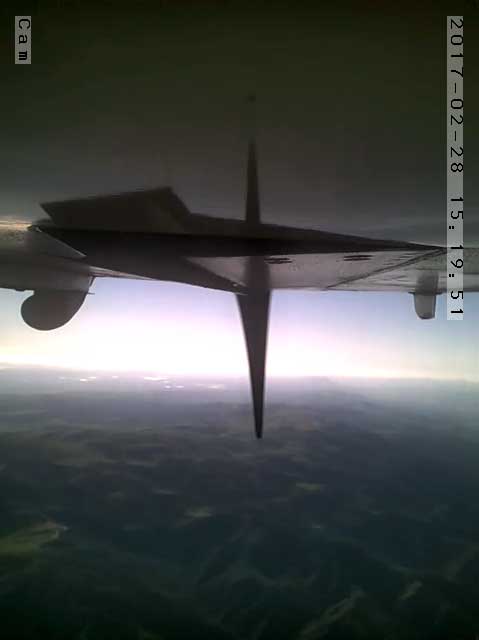
The odd-looking spike in the middle is a propeller blade. The object to the left is the exhaust pipe, and the one to the right is a fairing enclosing the engine breather and cloaca. The doors looked horrible, so today I jacked up the airplane and learned that the nose strut was not retracting fully and the tire was keeping the doors from closing. Fortunately, by shortening a certain link by a sixteenth of an inch I was able to get the wheel to retract fully and the doors to close perfectly flush. I noted, however, that the main gear doors were not closing fully either; they stick out a quarter-inch or more. That is a more difficult problem, because the tires are already touching the roof of the well and the doors are as close to the struts as they can be. The wheels retract under the seats, and there are already wells in the underside of the floor there to provide them with the greatest possible space. I believe that the back edges of the seats clear the floor by only a quarter-inch or so, so it may not be possible to raise the floor in the vicinity of the tires. Perhaps, however, I could cut two holes in the floor and seal them with rubber sheet.
[February 15, 2017]
A few days ago I replaced the paper filter element in the hydraulic system filter. I had expected this to be a troublesome job, because some time back in the 1990s an idiot using my body had installed the filter behind the instrument panel rather than in front of the firewall alongside the reservoir, where it obviously belonged. As it turned out, getting at the filter was not so difficult as I feared, and I managed to complete the job without spilling a drop of either hydraulic fluid or blood. The filter element was quite black. Here it is, like a patient etherized upon a table:
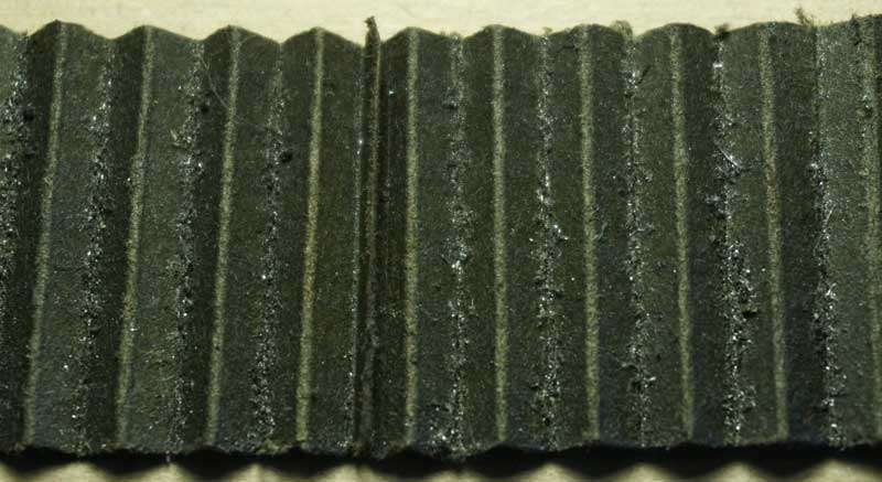
This is the sort of thing the NTSB has a field day with when it's found in a wreckage. The actual height of the strip is about 1.38 inches, and the spaces between the accordion pleats are about 1/4" wide. A closer look at about 20x magnification, its drama enhanced by Photoshop's "Auto levels" function:

To look at this you would suppose the hydraulic system would long since have failed, but it seems to work fine apart from occasional rebellions of the flap sequencer, which I pitilessly suppress. Where did all that finely-divided metal come from? There are 10 hydraulic cylinders of various sorts in the airplane, and a corresponding population of aluminum lines and flare fittings. I suppose the shiny debris represents the sum total of the fine metal dust that clings unnoticed to the insides of lines and cylinders fabricated and assembled under non-clean-room (to put it mildly) conditions. Or maybe the pump is disintegrating.
Apart from the eye-catching metal, the paper (originally a pale tan color) appears thoroughly clogged with black silt, which I take to be either extremely fine aluminum oxide dust or the wear products of Buna-N O-rings. Whatever the case may be, it appears that an inspection interval of less than 14 years -- well, 13.3, actually, no use being too hard on myself -- might be desirable.
[February 10, 2017]
Assuming that there must be some physical problem in the #2 (that is, left side, inboard) flap actuator, I removed first the actuator itself, then the master cylinder that drives it, and dismantled and inspected each of them. There were no problems that I could see; the O-rings were in good condition, as were the bores and the shaft surfaces. I put the system back together -- this whole cycle took about 8 hours -- and it worked correctly.
The problem was that the inboard end of the left flap had begun moving inward while the outboard end, as well as the entirely of the opposite-side flap, was going outward. This had to mean that back pressure in the exhaust side of the system was overcoming the pressure being delivered to the acuator by its master cylinder. This could happen only if there were a big leak -- and apparently there wasn't -- or if there were air, possibly at below-ambient pressure, in the line between the master cylinder and the actuator. There is a bypass in each master cylinder that is intended to restore the proper volume of fluid to the lines between the masters and their associated actuators, but for this action to occur the hydraulic pump must be allowed to run for a few seconds after the flaps are fully retracted. I have not been doing that, and I guess that may have been the root cause of the strange behavior. That, at least, is the straw at which I am now grasping, having had to discard the hypothesis of a faulty seal.
One thing that this adventure has brought to my mind is that the hydraulic fluid filter, which is in the exhaust side of the system just before fluid returns to the reservoir, has not been cleaned or even inspected -- note my self-exculpating use of the passive voice -- in 14 years.
[January 27, 2017]
Yesterday, after installing a new ELT battery, I went up for what was supposed to be a multi-purpose test flight. I had two cameras on the airplane, one under the left wing to check the closure of the main gear doors, the other on the canopy top looking down at tufts on the cowling top. It turned out to be rather choppy, in spite of being nearly calm on the ground, and so I didn't stay up long or do most of the things I had intended to do; it's a lot easier to fiddle with test equipment in smooth air. I did record an amusing but useless video of the landing gear retracting
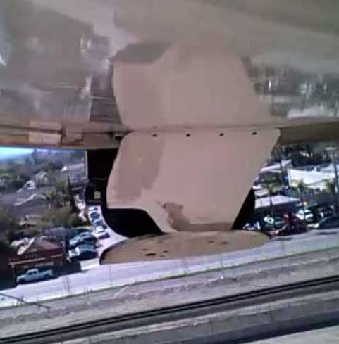
and confirm that the main gear doors are reasonably flush (that's the airbrake to the left; this is on 3-mile final at Whiteman).
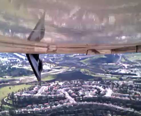
Now I need to point the camera at the nosewheel doors. I did not record the cowl top tufts, but I did observe them and noted that, as expected, they smooth out quite a lot when the cowl flaps are closed. I once measured a 2-knot speed difference between open and closed cowl flaps, but I don't have a lot of confidence in that number. In any case I think any speed difference would principally reflect the changing pressure drop across the engine rather than skin friction effects from turbulence on the cowling top.
There now seems to be a problem with my flaps. When I cycle them on the ground the inboard end of the left flap move inward when the flap is supposed to be going down. Hydraulics are inherently baffling, at least to me, but I think this must mean that there is a leak in either the master or the slave cylinder for the inboard end of the left flap. What is pushing the flap inward is the natural resistance in the vent lines. In flight, however, the behavior was different; the flaps went out in step, as expected, but halted before reaching full deflection; this could, I guess, be due to the aerodynamic resistance to flap extension (there is no resistance on the ground) causing the faulty O-ring to seat better. At least that is my hypothesis du jour. I at times wish I had operated the flaps with screw jacks and an electric motor, rather than hydraulically. I was concerned about the added weight of another electric motor, but I doubt it could have been any heavier than the synchronizer that controls the amount of fluid going to each of the four actuating cylinders.
Incidentally, it is interesting to compare two different presentations of the airspeed calibration curve from January 25. The left version looks pretty good; the right, awful. Same data, different first impressions.
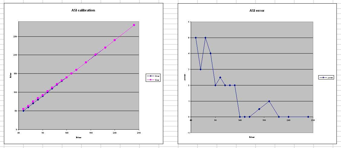
[January 25, 2017]
Out of the blue Brian Gerdes, who has done my biennial pitot-static-altimeter certification for years but whom I was unable to reach earlier -- that's why I ended up going back to Vista in the first place -- called me yesterday and came to my hangar today. He has a beautiful RVSM-worthy all-digital testing rig that he said cost $25,000. He made a small adjustment to my altimeter -- basically just slightly shifting the 29.92 point -- and it passed the test fine. He affirmed that there is no connection between the 30-nm Class B veil and the IFR pitot-static cert; the latter is required only for IFR in controlled airspace. The VFR test is of the encoder-altimeter correspondence and accurate reporting by the transponder; the altitude tolerances are much larger than the IFR ones. Gerdes also mentioned that despite the name there is actually no pitot test; the reason the test plumbing hooks up to the pitot tube is that if it didn't, the ASI could be damaged by being driven against the high-speed peg by decreasing static pressure, which it would interpret as increasing airspeed. Of course, there is a leakage test for the entire system, which includes the pitot plumbing.
[January 22, 2017]
As far as I can tell, the authoritative-sounding old-timer and longtime A&P who told me that I could not fly VFR within the LAX 30-nm veil was probably wrong, as authoritative-sounding old-timers, including me, frequently are. I can find nothing in 91.411 that suggests that the altimeter cert is required for anything except IFR operations within controlled airspace, veil or no veil. I suppose the Los Angeles FSDO may have invented a rule of its own; I have emailed them to inquire. The irony of all this -- apart from the fact that I never fly at 1,000 feet below sea level, and don't know anybody who does -- is that I myself am incapable of holding altitude for any length of time within the tolerance required of my altimeter. In fact, if one may judge from several midair collisions that seem to have been the result of highly precise GPS navigation, too much precision can be a dangerous thing.
[January 19, 2017]
Turns out I can't settle for a VFR pitot-static certification, because Whiteman is within the 30-nm veil of LAX. I am now looking at a digital altimeter from MGL avionics, and, alternatively, the possibility of overhauling my Bendix. All this because it's off by 50 feet at 1,000 feet below sea level! While waiting for news on that topic, I am figuring out how to mount an iPad in the cockpit, to serve as the display for my Stratus. I think it will fit under the throttle quadrant, tilted toward the pilot. Reflections are likely to be a problem, however; they always are, with a transparent canopy.
[January 12, 2017]
Yesterday, after working two or three hours a day for three days, I finally got the wiring harness for the gear position indicator light finished. I can testify to what every child who received an electrical hookup kit for winter solstice knows: that there is a deep satisfaction, after stringing a bunch of wires and throwing a switch, in seeing a light go on.
My altimeter failed the bench test; as was the case in the airplane, it had zero error until it got below sea level, and by -1,000 ft got 30 feet out of tolerance. I am grateful that this discrepancy was detected before I attempted a CAT3A approach to Furnace Creek or Bar Yehuda. For the time being, I will settle for a VFR cert, which does not entail strict altimeter tolerances.
[January 8, 2017]
Well, at least the world is not quite so mysterious a place as I briefly thought. In fact, my external power socket is correctly wired; what was wrong was the A&P's statement, which I blindly accepted -- after all, he is an A&P -- that the middle pin is ground. Actually, in an AN2551 plug and socket the large end pin is ground and the other two are A+. And start carts probably don't have reverse polarity protection. Maybe airplanes do. So my stupidity consisted not in wiring the socket wrong, but in not being more sceptical of authority. It's my German blood that does it.
Incidentally, punctuation pedants like me will have paused over the sentence three back. The phrase "which I blindly accepted" would normally be set off by commas, but in this case it is immediately followed by another parenthetical phrase set off by dashes. What happened to the second comma? If I had used parentheses instead of dashes, the second comma would have followed the closing parenthesis. But it looks strange, I think, to place a comma immediately after an em dash. Style handbooks often differ about points like this; Flying's style book is not infrequently at odds with my opinions and preferences. It would be amusing to see what the copy editors there, sometimes nemeses, sometimes saviors, would do with that sentence.
[January 6, 2017]
The day before leaving for the East I did some static system tests, using a plastic syringe to draw down pressure, and satisfied myself that the leak was at the nipple on the blind encoder. The Tygon hose with which parts of the static system are plumbed makes a less tight fit with it than with the barbed nylon connectors used elsewhere. I trimmed half an inch off the tube and reinstalled it. That seemed to solve the problem. .
We returned from Cape Cod on Wednesday, shortly after midnight. Today, I took the plane back to Vista, confident that all would be well. But it wasn't. There was still a leak. The A&P and I spent quite a while hooking into the system at various points to ascertain where the leak was. I finally tried putting some Vaseline on the blind encoder nipple to seal it better. We ran through a few altitudes, and found that now the altimeter was out of tolerance at altitudes below the field elevation (the test protocol starts at 1,000 feet below sea level) but nearly perfect above it. This suggested to me that the flexible hose was expanding slightly, and therefore leaking, under pressure, and shrinking slightly under suction; but Dusty, the old-timer who owns Vista, said that it was because the altimeter never sees those low altitudes. I didn't understand his reasoning -- you overcome stiction by tapping on the instrument, and I didn't see how the frequency with which a mechanism visit this or that portion of its range would affect its accuracy. In the end, I removed the altimeter from the airplane and left it there for them to bench test.
In the process we checked the ASI against the one in the testing apparatus. I'm not sure how perfectly calibrated that one is, but at any rate I noted down a rough calibration curve for my ASI which suggested that it indicates 2 knots high around cruising speed and around 7 knots high at stalling speed. For various reasons I don't regard these numbers as definitive; for one thing, I didn't notice that the ASI on the testing device had a calibration card. It's hard to imagine that it's perfect at all speeds.
One startling discovery, which came about when we hooked up an external power supply to operate the transponder, was that I have the external power socket polarity reversed. This is astonishing for a couple of reasons. For one, it is a huge, and hugely inept, mistake to have made. But okay, I make some beauties. More surprising, however, I have had a number of start-cart starts in the 14 years I've been flying this airplane, and there has never been an indication of a problem. I can only surmise that start carts have protection systems that sense battery polarity and supply voltage accordingly. And even assuming anyone notices a warning light or whatever, once the engine is running and you're waving goodbye nobody runs after you to tell you your socket polarity is wrong.
[December 15, 2016]
The simulation below turned out to be accurate. I put the plane up on jacks and raised the gear, and the link cleared the repositioned down microswitch. I installed the up miscroswitch, and now just have to put in the LEDs and wire them. That will have to wait until next year, however; we're going to Connecticut and Truro for the holidays. Very few people, it should be noted, go to Cape Cod in December and January. Why could that be?
At the start of the week I took the plane over to Vista, one of the the local FBOs, for its biennial pitot/static/transponder certification. There appeared to be a leak somewhere in the static system, and the test had to be suspended until I find and fix it. I was stupid not to remove all of the test hoses that I've been using for measuring pressures; some of them were connected to the static line. After I got back to the hangar I pulled out all that plumbing; it had become a nuisance for passengers and was not providing any new information anyway. Tomorrow I'll see if I can find the static leak.
[November 30, 2016]
Providing gear position indicator lights has turned out to be more complicated in execution than in conception. In principle, it's quite simple. Since the three gear struts are mechanically interconnected, microswitches can be put anywhere in the system to report the state of the entire system. (Not, of course, if something breaks; but let us moderate our imagination of catastrophe.) For a designer, many options are an embarras des richesses, or, as we anglophones have it, too much of a good thing. The place I originally thought I would use turned out to be impractical; the three-lobed joint visible in the photo below is too far from the frame behind it to allow convenient mounting of microswitches, and the inner wall of the fuselage nearby is encumbered with plumbing and cables. Some other locations within the wings were disqualified by the comparative inconvenience of routing wires to them. I finally decided to use the bellcrank in the right wing root that drives the torque tube going to the nose gear, which has a convenient bracket for attaching the microswitch assembly. Over the space of two days -- which is to say about four hours' work -- I built the support for the "down" microswitch, only to realize that it might interfere with the rod linking the bellcrank to the right main gear retraction link when the gear is up. Fortunately, I have a digital model of the gear system and can incorporate objects in it to test for interferences. I found this:

The little rectangle in the middle is the microswitch; the diagonal line passing beneath it is the link axis. The actual link is half an inch in diameter (the microswitch, for comparison, is 5/8 x 1"). So obviously the microswitch has to move upward at least 3/8", and the bracket has to be made again. But that's no surprise. Projects like this always involve making a few parts several times. You could make another airplane, defective in every respect, from parts that I've discarded.
[November 17, 2016]
I flew to Catalina today with a 6-foot 5-inch passenger. The chronic problem of inability to see the main gear torque tube through the passenger's leg was particularly acute, since I have all sorts of experimental hoses and whatnot on the floor, and his legs were already bent like an unborn foal's. So here's a new project: gear position lights. This should be an extremely simple matter, since all three struts are mechanically interconnected, and so it is possible to know their position with reasonable assurance -- with as much assurance, at least, as I have now -- by consulting the position of the torque tube. Skimming through this document, I see that the last time I resolved to make this minor modification was in May, 2012, after I almost landed gear-up. Four and a half years' procrastination -- that's about par for me.
I find to my surprise that I do not have a very good photo of the torque tube as it runs along the right edge of the cabin floor, but in the picture below you can see the white tube, the two silvery isoceles triangles whose apexes meet when the gear is fully up or down, and, if you have extremely sharp eyes and/or a good imagination, a corner of the three-bolt hub joining two segments of the torque tube. This joint, right next to a fuselage frame, is a convenient place to attach a cam and two microswitches.
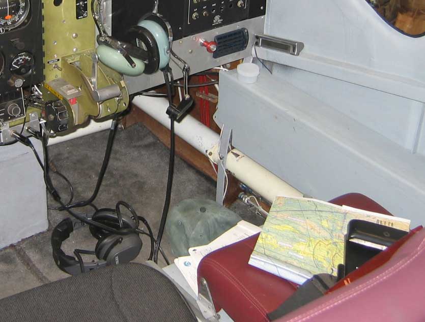
November 13, 2016]
Ah
love, let us be true
to one another! for the world, which seems
to lie before us like a land of dreams,
so various, so beautiful, so new,
hath really neither joy, nor love, nor light,
nor certitude, nor peace, nor help from pain;
and we are here as on a darkling plain
swept with confused alarms of terror and flight,
where ignorant armies clash by night.
[November 9, 2016]
Genesis 25:29
[October 18, 2016]
Yesterday I tried to record tufts on the upper surface of a cowl outlet vane with one of the two small video cameras -- the one that records to a chip. (Actually, both supposedly do, but I have only managed to get one to do it so far.) Unfortunately, the wifi connection quit as soon as I took off, and only resumed when I was back on the ground. I need to test its range; this camera has no antenna, unlike the other one. At any rate, I was reduced to attempting to photograph the tufted vane though the windshield with my phone camera. I also moved the wake rake to a position behind the right outlet and got a survey of velocities there. Here is the experimental setup; the camera is the tiny back dot at the apex of the triangle; the recorder-transmitter and battery are taped to the cowl top behind it. Although a few of the tufts appear somewhat aroused, the airplane is in fact standing still.
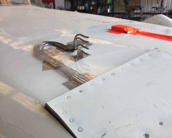
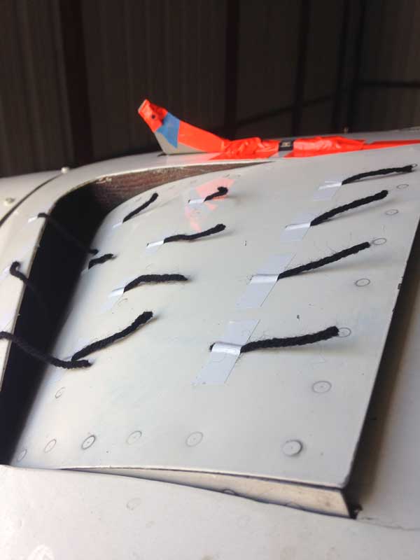
Here is the best picture I was able to get though the windshield:
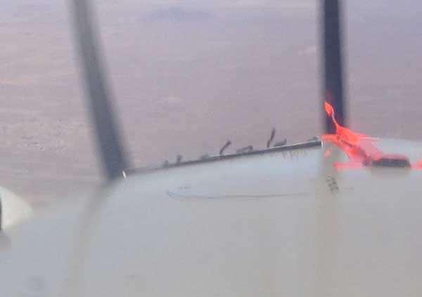
And here is the velocity distribution at intervals of 0.5 in. behind the outlet, and next to it the scan of velocities on the upper surface of the vane; the values in the box on the right are the size of the opening at the aft edge of the cowl flap:
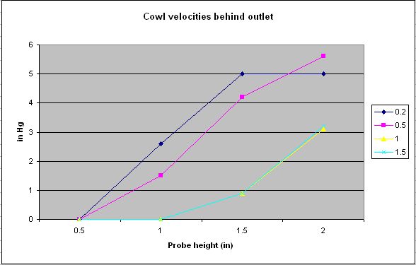
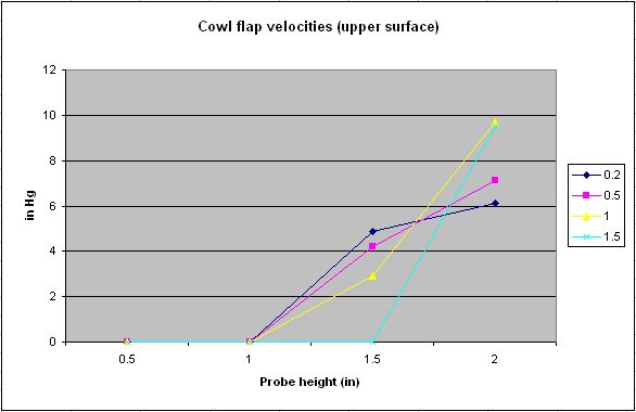
What to make of all this, I don't know. Evidently there is a layer of attached flow on the outer surface of the vane; the tufts there are lying down. It is not parallel to the direction of flght, however, but more nearly normal to the raked leading edge of the vane. This I already knew from oil streaks on the vane. Apparently there is an expanding plume of hot air behind the upper outlet, to judge from the longer tufts, which are taped to the upper lip of the outlet and appear to rise away from the cowling surface. They are waving around in a shear zone between the outlet flow and the free stream, however, and so a single snapshot does not tell the whole story. What is curious about the left-hand velocity scan is that the dynamic pressure at the test speed, 130 kias, is about 11 in Hg; the pressure observed 2 inches from the cowling surface is only half that, implying a velocity about 70% of free stream. One conclusion that can be drawn is that the discharged cooling air is not emerging at free stream velocity and is not making a seamless re-entry into the outer flow. It apparently forms a plume several inches thick.
The next experiment will be to tuft the top of the cowling and the windshield to see 1) how badly the flow there is disturbed by the cooling air outlets and 2) whether, as I optimistically suppose, the disturbance is damped by deceleration of the flow at the base of the windshield and acceleration over the canopy. We're going back to Greenwich for a week for a birthday party, however, and so I won't do that until early November.
[October 13, 2016]
I have been gradually, and more by accident than by design, unraveling the peculiarities of these tiny cameras. I have gotten to the point of downloading video from one of them to my computer; unfortunately, it is the 640x480 one (the $18 one) not the HD one, but I expect that sooner or later I will figure the HD one out too. Here is what the tuft array for the wing root test looked like standing still on the ground (left), and how the tufts lay at all speeds in flight:
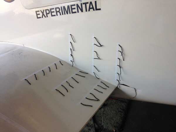
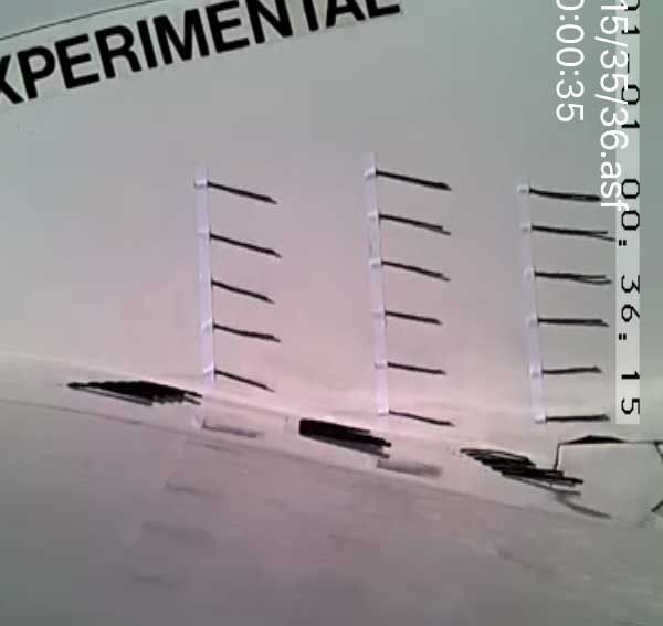
[October 11, 2016]
The first thing I did with the remote camera was tuft the wing root intersection and fuselage side from about 70% of chord aft. My intent was to see whether any separation exists at climb speed that might require a fillet. There was none; the tufts were glued to the fuselage side at all speeds. This was the intent of the fuselage design; the maximum width is at the trailing edge of the wing, and the fuselage meets the upper surface of the wing at a right angle. There is a little weakness on the wing upper surface near the trailing edge, which I had previously observed, but it is not related to the wing-fuselage intersection; it extends out a couple of feet, and is simply a consequence of the root profile being of 18% thickness with the maximum thickness far aft. So that result was satisfactory, except for one disappointment: The camera's image was visible on the iPhone, but nothing was recorded on the TF chip. I have to figure out what went wrong there. The only files I found on the chip were a couple of 640x480 ones from the first camera; and they were large in bytes, but played as blackness on the screen; so there is still a problem with that camera too. If worse comes to worst, I can always use the phone's screen capture function to get still images, but I would much prefer video.
In addition to the root tufting, I repeated my wake survey of the upper surface of a cowl flap. The results were perplexing. I did not see any signs of kinking this time, but the two probes closest to the skin yielded no readings at all. The outer ones did, but I did not understand their behavior. The free stream dynamic pressure at the test speed was around 11 in Hg. I need to repeat this test once again, after making certain that the two lower probe lines are not kinking.
I had also tufted the left aileron to see whether the internal seal had eliminated any indication of weakness; it had. There is an interesting eddy at the inboard end, however, when the aileron is deflected downward. It is due to air flowing through the comparatively large gap between the aileron and the flap and upper wing surface. Only the innermost tuft on the aileron itself is disturbed; the one next to it, on the wing surface just inboard of the aileron, is straight. I could do a better job of sealing that gap, but the problem is minor and exists only during brief moments when the aileron has a large downward deflection. It's interesting to note that the gap between the cove lip and the aileron surface seems to be smaller near the center of the aileron, possibly because the aileron is supported at its ends and flexes under load, and the center tuft is also the one lying closest to the surface of the aileron.
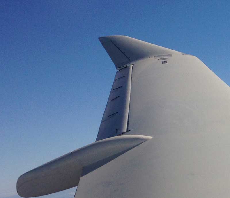
[October 7, 2016]
For some time very small HD video cameras with the ability to connect wirelessly with a smartphone have been on offer on eBay at very low prices. This seemed like a promising tool for doing tuft studies without having to struggle with a festoon of wires from the camera to the cockpit. A couple of months ago I got one for $18 but was unable to get it to work; my phone never managed to hook up to its network address. I ordered a second, for $36, with equally little success. Thinking that I might be failing to properly follow the directions, which are inscribed on a slip of a paper in 0.5-point characters, Chinese on one side and a literal English translation on the other, I asked my son to have a go -- the septuagenarian's usual solution for digital bewilderment -- but he had no better luck than I. I returned that one and got my money back. After a period of mourning, I ordered a third camera, this time for $29. This one worked; or maybe I just finally understood how to work it. I mounted the camera and its associated circuit board, battery and antenna on an inverted aluminum T in order to be able to tape it securely to the skin of the plane.
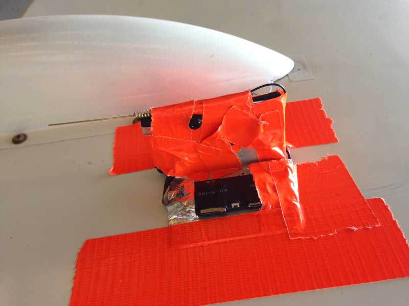
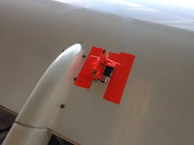
The camera is the little thing peeking out of the field of orange tape. For scale, the tape is two inches wide and the mount two inches tall. An app on the phone turns recording on and off; the video is recorded on a chip that mounts in a socket on the edge of the circuit board.
Remarkably, after I got the third camera working, the first one started to work. Next thing you know, I'll be speaking Mandarin.
I also revised the mounting of the wake rake on the cowl outlet. I'm hoping for a big day of data gathering on Monday.
[September 28, 2016]
My first effort to measure cowl outlet velocities failed. The vinyl tubes kinked just in front of the aluminum tape when the cowl flap rotated to the fully-open position. Also, as I suspected might happen, the heat softened and loosened the duct tape. The metal tape was undisturbed, however, and when I get back from Post Angeles, Washington, where we are going tomorrow for a few days, I will replace the duct tape with metal tape and revise the routing of the vinyl tubes so that they will not kink.
[September 23, 2016]
Returned from the East yesterday. Today I installed the pressure rake that has been sitting around since last March but one. My plan is to collect measurements for four cowl flap settings for each of the two exit streams, one above and the other below the cowl flap, which doubles as a turning vane. I am hoping to learn something about the velocity of the exit stream. After collecting data with the rake on top of the flap, I will move the rake to a location just behind the flap and repeat the measurements. (In the picture below, the cowl flap is closed, but when it is opened there is a sepoarate outlet stream below its trailing edge.) I doubt that the results will be useful in any way, but they may be instructive.
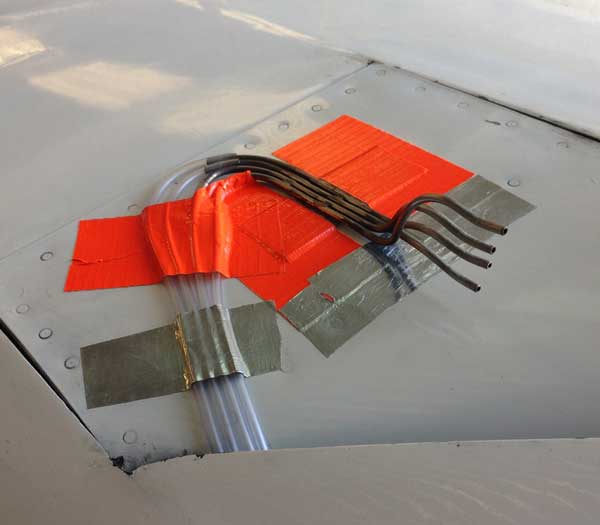
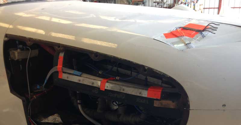
The aluminum tape is there to be sure that the orange duct tape does not let go because of the heat. The four hoses go to four 1/8" steel tubes bonded into the firewall for this purpose; they are in turn plumbed to a four-valve manifold (from an aquarium supply shop) and to the inches-of-water gauge in the cockpit.
[August 26, 2016]
On the 18th I went to Santa Paula to see the Harmon Rocket (something like an RV-4) equipped with a 650-hp rotary engine that is preparing to challenge the absolute records for a propeller aircraft of record for time to climb from a standstill to 10,000 feet. What that record is, I don't know, but it may be 91 seconds in a Grumman Bearcat. Anyway, I figure the airplane, which will weigh less than 1,200 pounds with fuel and pilot, should get off the ground in less than 200 feet and climb at something more than 12,000 fpm. For some reason its wings have been clipped, which does not make sense to me; it must have been done to reduce weight, but I would have thought that in a climb the span would be worth more than the weight saving. The oddest thing about the airplane is that it has no cowling. The engine, with all of its plumbing, air and oil radiators and general clutter is left out in the breeze. The reasoning is that at 90 kias parasite drag will be a minor factor. Actually, this is not quite true; at best rate of climb speed, which is bound to be close to the best L/D speed, parasite drag is half the total drag. At any rate, I did some calculations, making various unfounded assumptions about the drag contribution of the engine, and found an impact of several hundred feet a minute. I did take into account the fact that a cowling would add weight at the same time as it reduced drag. The cooling drag, of course, would still be there. Anyway, the day after my visit the airplane made a couple of hops down Santa Paula's runway. The record attempt will be made at California City, near Mojave. Unfortunately, I will probably be on the east coast when it happens; we're leaving next Friday for an absence of three weeks or so.
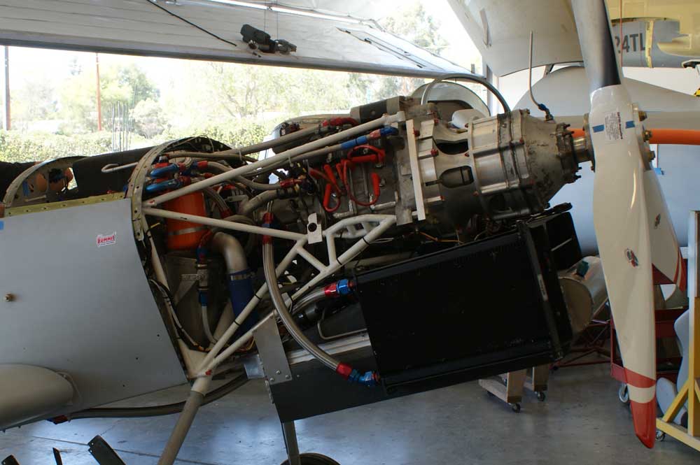
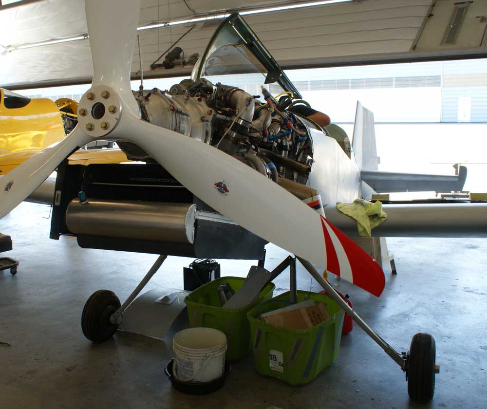
[August 5, 2016]
Continuing in my new tradition of doing nothing of consequence, I added screws to secure the back-seat armrests, which have been held in place by the force of gravity for the past 12 years or so. I felt some hesitation about adding the weight of nine 3/8-inch-long 8-32 screws and their associated nutplates when they were so obviously unnecessary, but I overcame my scruples. Unfortunately I had the bright idea of using some Click Bond adhesive left over from a 2009 project to secure the nutplates. The two-part stuff completely failed to cure. I later looked up its shelf life, which is said to be one year. I then had to clean the horribly recalcitrant goop away before attaching the nutplates with a different adhesive, namely, Super Glue. Eventually I got the armrests secured, thus making the occasional inspection of certain cables, pushrods, tubing and wires somewhat more inconvenient and less likely to occur. Next big task: Velcro the carpets to the floor!
[July 21, 2016]
Two giant steps for mankind. First, I finally located the sheet of transfer lettering I bought a few months ago and promptly lost, and added the letters O (oil) and A (air) on either side of the temperature selector toggle switch. Second, on the suggestion of Russ Hardwick I added half of a 1/4" dowel to the back (ie uncalibrated) side of my carbon-fiber fuel dipstick. Russ pointed out, during one of our periodic lunch meetings, that a porous material like wood would hold visible fuel longer than the carbon fiber. It does. The suggestion was reinforced on the 9th when I observed Chuck Wentworth dipsticking the fuel in the Trimotor with what appeared to be part of an old broomstick.
[July 10, 2016]
Yesterday I parked, as I had determined was advisable, with the flaps out a few inches and the flap handle in the retract position. The plane sat in the hot sun for hours without ill effect. I described the problem I had had on June 4 to Chuck Wentworth, who said that he had experienced something similar with Javier's dark-blue Corsair. If it sits too long in hot sun with the wings folded, hydraulic fluid leaks out of the wings. The reason is the same: the fluid expands, raising pressures above the design values in the sealed-off parts of the system. This must have been a regular occurrence in the Pacific theater during World War II.
I have been meaning to show the checklists, to give a sense of the flavor of operating M2. Here they are:
Before start
Preflight
inspection complete
Sumps and gascolator drained
Chocks and tiedowns removed
Flight control locks removed
Pitot cover removed
Gear lowering ratchet, #2 Phillips screwdriver available
Seat belts fastened
Fuel shutoff valve open
Check visual gear-down indication
Cycle airbrake lever through retract position
Flap and gear handles centered
Check breakers
Pump brakes for feel
Start
Cowl
flaps
fully open
Radios off
Windows secure
Mixture rich
Master switch on (check voltage = 24)
Hold reset button on fuel totalizer until blinking stops
Check fuel quantity indication
Check total fuel on totalizer
Mags on
Clear area
Cold start:
Throttle open 1/2"
Fuel pump high for 8 seconds before cranking
Hot start:
Fuel pump high for four seconds, then off
Throttle open one inch
Begin cranking, then turn on fuel pump
Use full throttle/lean mixture if flooded
Check fuel and oil pressures
Before taxi
Turn
on GPS
Check gyro suction
Check stall warning
Check AH erect
Set DG
Set altimeter
Set clock
Check ammeter for indication
Check CHTs for indication
Select inboard fuel senders
Oil/air temp selector on oil (left)
Check parking brake released and safe
Radios as needed
XPDR on standby
Neutralize roll trim
Set pitch trim
Controls free and moving in correct directions
Select fuel tank on inside of turn onto runway
Obtain clearance if needed
Runup
RPM
to 1,700
Check mags for drop less than 100 rpm
RPM to 1,800
Cycle prop (first runup of day only)
Pre-takeoff
Flaps
set
for takeoff
Doors latched
Airbrake handle in detent, light off
Auto fuel switcher OFF
Autopilot OFF
Mixture rich
Prop fine pitch
Wastegate open
Lights as required
Transponder on Mode C
Cowl flaps to climb position
Climb
Retract
landing gear
Accelerate to climb speed/alpha
Retract flap
Set climb power (34/2500 for high performance, 28/2500 normal, 27/2300
and 50 LOP for economy climb)
Check fuel flow
Check oil pressure
Check XPDR reply light
Auto tank switcher on when balanced and roll trim neutral
Monitor CHT, EGT, OT during climb
Use wastegate after throttle is fully open
Cruise
Mixture
to
25-75 lean of peak (TIT)
Adjust cowl flaps as needed (CHT < 200 C)
Descent
Close
cowl
flaps
Open wastegate as appropriate
Before landing
Fuel
on
proper tank
Auto tank switcher OFF (not while cycling)
Park brake OFF
Mixture rich
Prop fine pitch
Wastegate open
Airbrake deployed
Landing gear down and locked (100 KIAS max)
Flap as required (90 kias max)
Open cowl flaps fully
After landing
Transponder
to standby or off
Retract airbrake
Retract flaps
Sufficient delay before shutdown to cool turbo
Manual landing gear operation
If the hydraulic pump does not work, perform the following steps:
1.
Pull
both landing gear breakers
2. Open the bypass (faucet handle below passenger's knees)
3. Trim to 90 KIAS and engage the autopilot to reduce workload
4. Put the gear handle in the DOWN position
5. Rotate the manual overcenter (large bolt head under pilot's knees)
with the ratchet. Place the ratchet handle to left of socket and lift,
moving the ratchet clockwise as viewed from the rear, until the gear
free-drops. Do not force the ratchet; little effort is required, and
only a few degrees of motion. If it does not rotate easily, check that
the gear handle is in the DOWN position.
6. Verify down-and-locked indication on torque tube
If
the gear
control valve does not respond to the
handle on
panel, you can either operate cables directly (right side of cockpit,
near floor) or remove the panel under passenger's knees and rotate the
valve pulley by hand. If necessary, move the flap and airbrake handles
in order to determine which cable pair controls the gear valve. The
spade fitting on the cable from the valve should move forward for gear
down.
[July 9, 2016]
Today I logged a few minutes at the controls of Javier Arango's 1929 Ford Trimotor. It is quite stable in smooth air, and very heavy on the controls, especially the rudder, considerable and well-timed doses of which must accompany every turn. The pedals feel as though they are welded in place. Chuck Wentworth said that to get the rating you have to demonstrate handling with one engine out; this involves placing both feet on one rudder pedal, pushing with all your might until the general principle has been demonstrated to the satisfaction of the examiner, and then calling for help. There are three fuel tanks whose contents are dipsticked by climbing up on top of the wing through a hatch in the cockpit ceiling. You're 12 feet in the air on a curved metal surface with few handholds -- far more dangerous, I think, than mere flying. Pan Am used to fly these cross-country, cruising at 100 mph at up to 10,000 feet, with 12 passengers. The engines are uncowled P&W 985s of 450 hp and 20 gph each. They set up an ungodly howl on takeoff -- supersonic prop tips -- but at 1,800 rpm in cruise the main noise is the hiss of wind. The designers seem not to have been overly concerned about drag; note the external control bellcranks.
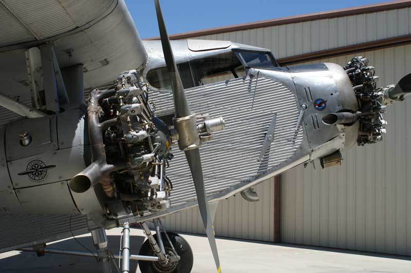
[June 29, 2016]
Today I finally put in the right-hand aileron seal and flew for an hour. As far as I could tell, the seals made no difference to either roll rate or stick forces; at least whatever difference they made was too slight to notice. The temporary seals are made of a thin, porous polyester cloth that I normally use as peel ply. I doubt that an impervious material would be greatly different, but I guess, since it's not very difficult to install the seals, I will order some teflon tape and make permanent ones.
[June 26, 2016]
After I installed a temporary aileron seal on the left side, a series of obstacles prevented me from getting back to the airport to put in the other one and test fly them. Probably next week. In the meanwhile, I received through Javier Arango a photo that warbird photographer Frank Mormillo took of my plane as I was leaving Paso Robles on the 4th. It's a nice picture and the only decent in-flight shot of the plane in its presumably final configuration, so I put it in place of the now rather dusty old picture that has opened this site for the past dozen years.
[June 6, 2016]
The coefficient of thermal expansion of 5606 hydraulic fluid is 0.0005 per degree Fahrenheit. The fitting that failed was in a volume consisting of a couple of feet of 1/4" hose or tubing and an actuating cylinder with a 15.2 inch travel and an internal diameter of 0.91 inch. The volume of fluid in the cylinder when the flap is retracted is 9.9 cu. in. The volume of fluid in the lines is comparatively negligible, but let's say the total fluid volume involved is 10 cubic inches. If its temperature rises by 50 deg. F, its volume increases by 0.25 cu. in. The volume increase must be accommodated somehow. The flap is already up against its forward stop, so the accommodation has to come from expansion of the aluminum hydraulic cylinder and the nylon and aluminum lines.
It would be tedious to calculate how much each would have to grow, given their respective tensile moduli, and I'm not sure I would do it correctly anyway, but it's evident that it was easier for the nylon line to pop out of its compression fitting than it was for everything to expand. It's also evident that if the flap piston were free to move, a displacement of about .38 in. would relieve all of the excess pressure. Now, for the flap to move the fluid on the other side of the piston has to go somewhere. Where it goes is to the associated master cylinder in the synchonizer assembly, which in turn has to move about 1/16". That movement would get passed on to some more nylon and aluminum lines, and to the flap-extension side of the other three master cylinders. There is a pressure relief valve there, however, that would presumably protect the system. So the way to prevent fitting failures due to thermal expansion of the hydraulic fluid would seem to be to park with the flap extended an inch or two.
Now that I think about it a little more, an even better way would be to park with the flap handle in the retract position, rather than neutral. Then expanding fluid would be free to flow to the reservoir, and there would be no pressure build-up at all.
I'll try to remember that for the next barbecue.
[June 5, 2016]
Yesterday was the annual Antique Aero barbecue at Paso Robles. It was a hot day, as usual. When I was leaving, I taxied to the departure end and ... Well, never mind; you can read the whole story in the entry for June 6, 2015, because exactly the same things happened again -- partial flap extension, same hose blew off same fitting -- with the sole exception that this time all the hydraulic fluid ran out, and there was none left to retract the gear. I returned, and with the generous help of a couple of the guys who work at Antique Aero I got the flap hose reconnected and the hydraulic fluid replenished and flew back to LA without flaps or incident.
Since the fitting that failed both times is in a vent line, and therefore under very little pressure, when the flap is being extended, my current hypothesis is that both this year and last the fitting popped off while the airplane was parked, and that what made it pop off was simple expansion of the hydraulic fluid due to the right side of the airplane baking in the afternoon sun. I suppose this could be prevented by either 1) not going to the barbecue any more or 2) parking with the flap slightly extended or 3) revising the plumbing to replace some of the nylon lines with actual aircraft lines with flare fittings -- which I have avoided doing because of the expense -- or at least replacing the long, loose runs of nylon line with aluminum and using nylon only where the attachment fitting can be aligned in such a way that the nylon lines are loaded as short columns and would resist popping out by their own compressive strength.
[May 20, 2016]
I sketched out the design for the aileron seals.
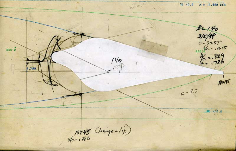
If I were Leonardo da Vinci, this yellowed palimpsest would be valuable. There is, at any rate, some history to it. The date of 3/5/88 refers to when I initially drew the BL 140 aileron on an airfoil profile drawn by a Swee' P plotter. The blue profile is the operative one; I'm not sure what the green leading edge is doing there -- probably economising on paper. The white profile is the shape of the new ailerons; the circular-arc nose of the old aileron is visible behind it. The seal design requires a shelf, about 0.6" wide, protruding from the middle of the rear spar. The seal -- curved lines going to the two extremes of the aileron travel -- would be secured to it and to the underside of the porpoise-nose of the aileron with two-sided tape. It happens that I still have some of the wing spar cap material that I laid up long ago and that is about the right thickness and length. It's the same stuff as I used for the aileron spar caps. I'm planning to install a temporary seal first to be sure that handling is not adversely affected.
[May 16, 2016]
It was a great pleasure to fly again after an absence of several weeks. The engine started immediately, and it, the airplane and the air were all smooth and contented-seeming.
Casting about for some new project, I have settled upon that of sealing the ailerons. The original ailerons, which I replaced in 2013, had circular-arc leading edges, small gaps, no aerodynamic balance and no seals. The new ones have partial aerodynamic balance (that is, the nose of the aileron extends farther in front of the hinge line), no seals, and, because of their nose shape, larger gaps. I did not notice any change in speed when I switched ailerons, so the drag increment from the larger gaps was apparently small. Nevertheless, it is preferable to prevent crossflow from the high pressure side of the wing -- normally the underside -- to the low pressure side, and the aerodynamic balance is more effective if air is not allowed to leak around the nose of the aileron. External gap seals, consisting of flexible mylar blades that would touch the aileron surface, would prevent crossflow but would also reduce the effect of the the aerodynamic balance. The alternative is to install a fabric diaphragm between the aileron and the wing. That is what I think I will try to do. It's a little tricky, because the diaphragm must be short enough not to prolapse through the gap, but long enough to allow installation and removal of the aileron. Theoretically, a seal of this type should both increase aileron effectiveness and reduce stick forces. We shall see.
[April 18, 2016]
EBay delivered up a functioning CHT probe, which is now installed. Before I put it in I checked its continuity. Sure enough, it had a low but not negligible resistance, so my theory that at the very least a thermocouple should display electrical continuity received some support. I re-checked my two spares, which obstinately refused to let a single electron through. They ended up in the trash can, poor things. I flew for an hour; the CHT of the #5 cylinder was about the same as that of its counterpart on the other side. My CHTs go by pairs, with the rear cylinders being the coolest and middle ones the hottest. It would be nice to be able to boast that all are the same, but since they are all at or below the recommended 380 F, I guess it doesn't make much difference.
A number of people very kindly wrote, anent my gloomy reflections of March 31, that they like reading this stuff, no matter how trivial it is. So I guess I'll keep it up. Not for the next two or three weeks, however; Nancy and I are going to the east coast (not in Melmoth 2) for a grandkid's birthday and a little time on Cape Cod before the crowds arrive. Odi profanum vulgus et arceo, as Horace used to say.
[April 9, 2016]
More systematically this time, I checked continuity throughout the CHT wire harness. All good. So I went over to the biggest repair shop on the field, Able Air, and asked a mechanic, who happened to be working at the time on precisely this problem in a twin Cessna, if they had a way to test thermocouples. He said that they just swap them between cylinders and run the engine -- a real pain in the neck, since they tend to be pretty well secured, and if they fail you have to take them out twice. I don't understand why they don't just connect them to an old CHT gauge and warm them with a heat gun or a soldering iron. But anyway, he went on to say that any balky thermocouples over 15 years old they just replace. He seemed certain that both of my "spares" were bad -- as in fact the lack of electrical continuity across them suggests, at least to me. Mind you, all of my thermocouples are 1970s vintage, so the 15-year rule must be applied gently. Next stop, eBay.
[April 7, 2016]
Yesterday, in the vein of continuing minutia, I tried to do something about the inoperative CHT indication on the #5 cylinder.
The system consists of six bayonet-style thermocouples connected by a few feet of two-conductor iron-constantan wire to a 12-pin Molex connector. The other side of the connector is a short pigtail to a three-position rotary switch which selects cylinders in pairs -- front, middle, rear -- and sends the selected signal through a pair of trim potentiometers to a dual CHT gauge. The purpose of the trim pots is to correct for the various junctions in the system and for the fact that not all of the wire is the proper iron-constantan. The calibration system is the usual cup of boiling water.
The possible points of failure, therefore, are many. But since all of the other probes work, the problem cannot be between the selector switch and the instrument; it has to be between the thermocouple and the rotary switch. The connections to the selector are soldered and the wires are tightly tied to the switch body with lacing cord, so, unless I have a cold solder joint there -- and that is not particularly probable, since the #5 CHT used to work -- the fault is not likely to be at the switch.
Based on past experience, I would be inclined to suspect the Molex connector, because its connections are crimped. On the other hand, bundles of 12 wires, tied at close intervals, are very stiff, and so their connections are less likely to fatigue than single wire terminals are. In the past, however, I had a CHT problem that was due to a broken, albeit quite stout-looking, connection between the thermocouple pigtail and the iron-constantan wire, so you never know.
I decided that the place to start was to check continuity between the thermocouple and the rotary switch. So I opened the cowling and disconnected the thermocouple. At this point I went off the rails. Thinking that a thermocouple is a bimetallic junction and therefore ought to have a low resistance, I checked the thermocouple with an ohmmeter and found infinite resistance. (I know this is not the proper way to test a thermocouple. but all I was interested in was continuity.) Aha, I thought, there's the problem; the junction has failed. So I hunted up a spare bayonet, installed it, put the selector back into the panel, and zipped everything up without ever conducting my intended tests of continuity between the probe and the switch.
I started the engine. The #5 CHT did not indicate.
Tomorrow is another day.
[March 31, 2016]
Yesterday I wired the landing light and lit it up. It worked.
According to legend, Alexander the Great, having subjugated various tribes all the way from Macedonia to India, wept because there were no worlds left to conquer. Alexander considered himself quite a fellow, but it is noteworthy that in all the ancient annals of Indian history there is no mention of his arrival or departure. He was a raindrop in an ocean, gone without a trace. My illusions about my own grandeur are not on the scale of Alexander's, but I am beginning to get that no worlds left feeling myself. All the goals I have set for myself with Melmoth 2 have been either accomplished or discarded. I am reduced to nugatory stuff like adding an armrest or fixing a leak. This 14-year record of tests and modifications is in danger of degenerating into a mere maintenance logbook. Perhaps it is time to put it to rest.
[March 24, 2016]
Stopped at Luky's on the way to the airport to pick up an AN822-3D fitting. Arrived at the hangar, I found the flap actuator still dripping, ostensibly from the elbow under the trunnion. This is what the thing looks like (also here), and this is about the only angle from which you can see or approach it:
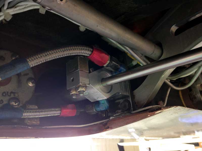
I took the actuator out for the third time -- I'm getting quite good at it -- and replaced the fitting. I then reinstalled the assembly and ran the flap -- and it leaked worse than ever. I could hardly believe it; even a damaged joint could not leak that badly. I was gazing at it in wonderment when I saw a drop of hydraulic fluid fall onto the fitting from above. At first I thought it might be coming from the seam between the trunnion and the cylinder, but that seam was dry. I realized then that it must be coming from a fitting behind the top of the trunnion, not visible in the photo or for that matter in real life either. So I took out the actuator yet again, and found that the B-nut on that top fitting was not even finger tight. So after all that the problem had been a stupid oversight of assembly when I last overhauled the actuator, a year or two ago! How it managed to pass yesterday's pressure test I cannot guess. I tightened the fitting, put everything back together again, and it worked without leaking.
[March 23, 2016]
The landing light is now in place on the right main gear door; not wired yet, however.
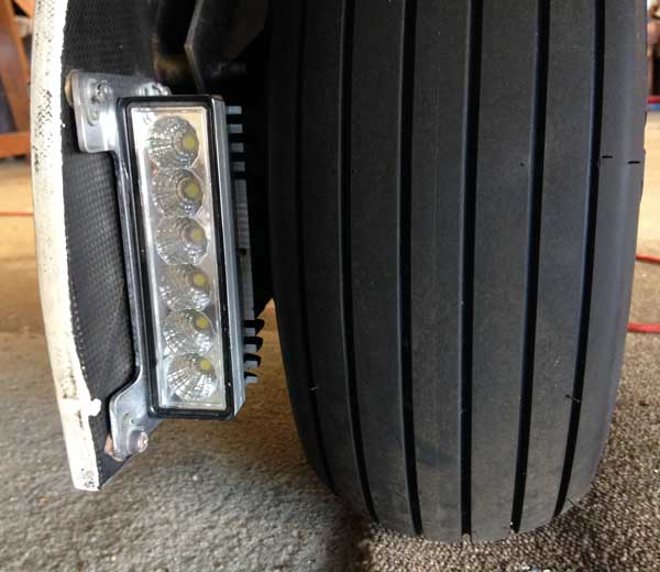
In the meantime I removed the left outboard flap actuator in an effort to discover the source of a persistent escape of hydraulic fluid. I have repeatedly put folded-up paper towels into the niche that the cylinder occupies in the wing in an effort to discover where the leak is, without success. This time I rigged up a testing apparatus that consisted of a second hydraulic cylinder that I could squeeze in a hydraulic press, ducting fluid from it to the actuator in question through one port while the other was capped. This had the effect of pressurizing both sides of the piston, and therefore of potentially revealing a leak anywhere in the cylinder. At 500 psi, which is about as much as this actuator ever sees, no fluid appeared. When I put the cylinder back into the wing, however, one of the connections to it leaked copiously. The flare fitting, on close examination, may be slightly damaged -- though I would not have thought so had it not leaked. The fault could also be in the hose fitting, though that seems less probable, since it is steel rather than aluminum and so more difficult to damage. It is also more difficult to inspect. I'll replace the aluminum AN fitting today and hope that solves the problem.
[March 16, 2016]
I had a couple of strokes of good luck. Rummaging in my piles of detritus I found the uplock assembly for Melmoth 1's nosewheel, and it happened to incorporate a precisely suitable type of microswitch for sensing when the gear is down and illuminating the landing light. This could be seen as an argument for never throwing anything away, which is not quite my policy, but almost. I thought I was going to have to bond a couple of tabs in the wheel well to which to secure the switch, but as luck would have it I had, some time in the 1980s, incorporated a gusset that happened to be in exactly the right position for mounting the switch, which I did this afternoon. I omitted this gusset on the other wing without apparent ill effect. I can no longer remember, in fact, what it was supposed to do; but when its time finally came, it performed nicely.
[March 11, 2016]
I amused myself during the final episode of Downton Abbey -- our long national nightmare is finally over -- by hand-stitching a leatherette cover for my armrest. In dim light, with peripheral vision, it doesn't look bad. The combination of moving the sidestick back 3 inches and adding the armrest has improved the consistency of my landings, since I now rely on wrist rather than upper-arm action to flare.
I have now turned my attention to the landing light, which has been lying around for a year since I machined a lot of material off its housing to lighten it. (It was intended for a dune buggy, where weight is apparently not a serious consideration.) I had provided it with two mounting holes for 10-32 screws. These did not provide a convenient way to adjust its aim, however, so today, during a furious rainstorm -- all rainstorms sound pretty furious, to be sure, when you're working in a metal hangar -- I made a mounting plate out of .100 aluminum with holes at four corners through which four countersunk 3/16" screws will secure the light to the inside of the right upper wheel cover. Shimming the two front holes will allow adjusting the azimuth. The elevation is a bit more of a puzzle. I suppose the light should be pointed more or less at the landing aim point. A few online sources of uncertain infallibility mention values like -4 or -5 degrees, which must represent the negative of the angle of attack at approach speed. I calculated my angle of attack at 70 knots and 2,200 pounds with full flap and it's around -2 degrees, so the landing light should be aimed up, not down. I guess I'll just point it straight ahead. It will have to double as a taxi light, but it will not be a very good one, since it will be just a few inches above the ground. My idea at the moment is to wire it in parallel with the nav lights, with a microswitch actuated by the landing gear, so that the landing light would be on at any time the nav lights are on and the gear is down.
[February 25, 2016]
Before leaving on February 14 for a week and a half in the East, I rebuilt the exit duct for the oil cooling air to make it less restrictive. On returning testerday, I tufted the oil cooler air outlet. I had done this previously, but then I had placed the central tuft a few inches behind the outlet, where it lay down smoothly enough. This time I put one row of tufts immediately behind the outlet, and found that the middle tufts were jumping around like mad. By the time I landed they were in shreds. Reasoning that this bubble of vorticity could not possibly be helping the exit flow, I added a couple of turning vanes made of .010 aluminum. The flow is now smooth. Whether this change had any effect on cooling or anythng else, I don't yet know, but at least it's nice to know that the flow is now orderly.
The pictures below show, respectively, the rebellious tufts, the turning vanes as seen from outside and inside (temporarily held in place with aluminum tape; now that I know they work, I'll epoxy them), and the tufts brought to heel. It's interesting that the flow at the second row of tufts in the first picture, which is 4 or 5 inches behind the first, appears to be quite smooth and attached in spite of the turbulence immediately ahead of it; the outer tufts indicate a converging flow. The fourth picture is not very clear -- it's a small portion of a larger one, and taken through an optically poor area of the windscreen -- but at least it's obvious that none of the tufts is standing up.
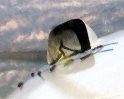
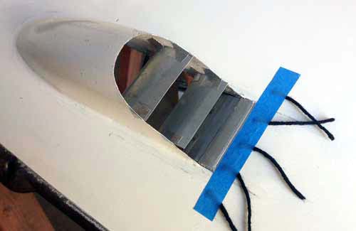
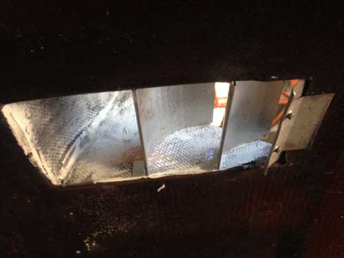
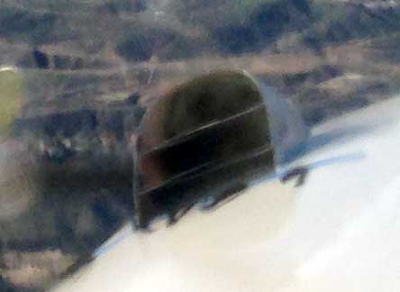
[February 3, 2016]
At least for the time being -- winter, that is -- I am resolving the oil temperature problem by declaring victory. The "desired" oil temperature range, according to the overhaul manual for my engine, is 150-200 deg. F. I have been aiming for 78 C, or 172 F. On line, however, I found a persuasive recommendation by Mike Busch, who is a pretty reliable authority, of 180-200. So I took a small piece of green tape and affixed it to the face of the oil temp gauge to mark a "desired" band of 80 to 93 deg C. I flew for an hour today, climbed to 10,500 feet, set up a 6.3 gph cruise at 22.5/2000 for a true airspeed of 156 knots, and the temp stayed within that band. That will do for the moment.
The picture was taken during the descent, so the oil temp has come down a bit; but it gives the general idea.
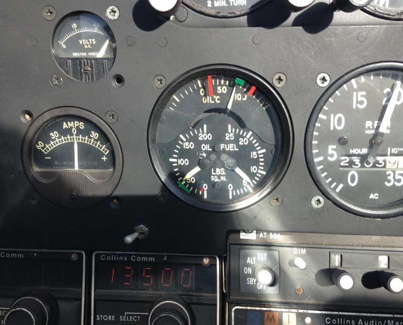
[February 1, 2016]
No further work done on the oil cooling, but I hard wired the GPS, thereby liberating the 12v outlet for the iPhone charger. Probably I can use that power, and a cell phone car charger, for the Stratus as well. No doubt Peter Lert will tell me, as soon as he reads this.
[January 16, 2016]
Alas, the new duct is scarcely better than the old. It got me perhaps 7 degrees C of improvement, not the 20 I was hoping for. It is still in rough form and may be slightly improved by adding a bellmouth (that is, rounding the edges at the inlet) and sealing the small holes along the riveted edges, but it is still not going to do the trick.
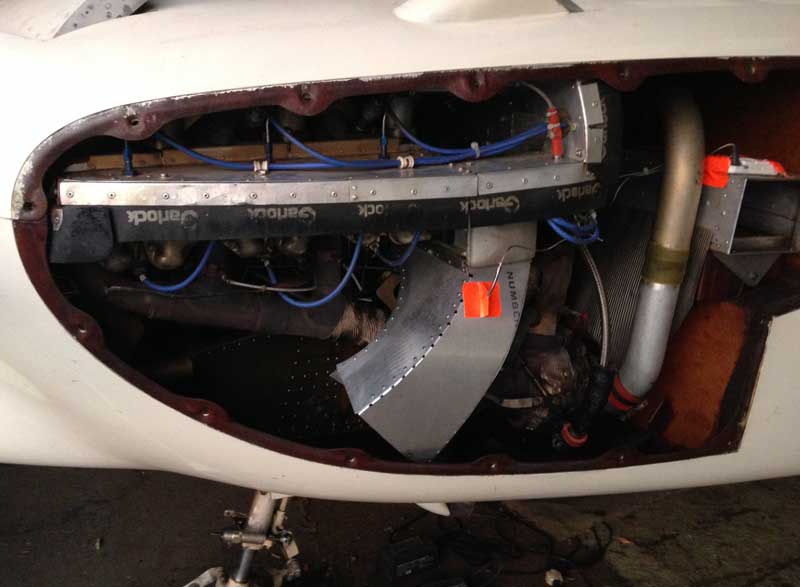
January 13, 2016]
The new oil cooler inlet duct is almost complete; only a couple of seams remain to be riveted. I am building it on the theory that the existing duct is too restrictive. The new duct's inlet area is about 2.5 times larger, and, possibly more important, it does not converge so rapidly toward the face of the oil cooler. The old inlet duct -- its purpose is to suck up air from low in the the high pressure plenum before it has been heated by the exhaust pipes, turbocharger, and so on -- used a straight, wedge-shaped hood over the cooler. According to Kuchemann and Weber, the authors of the canonical text on this subject and, incidentally, a married couple -- how nice that they had a shared interest -- a more voluminous and convex hood is desirable. My hope is that the oil temperature will settle at 78 C, as Continental says it should. If that does not happen, I will have to start thinking -- well, not start, because I have already thought -- about a protruding scoop to bring cold outside air to the cooler. Such a scoop would be located about where the NACA inlet for engine induction air is located now, and would replace it as well. The conventional wisdom -- not to mention common sense -- holds that inlets should not be multiplied, and that it is better to take in all air -- heating, ventilation, engine cooling, oil cooling, intercooling, accessory cooling, etc -- through one large well-designed inlet. It is not clear, however, how the penalty for each additional inlet might be balanced by its particular advantages. For example, because of the engine cooling being of the updraft persuasion, air getting to the oil cooler is being preheated as it swirls around in the lower plenum. I could run a duct from the front inlet back to the oil cooler, but it would be almost three feet long and would entail a pressure loss. Air brought in from the free stream close to the cooler would experience almost no pre-heating and would also have slightly better pressure recovery. Removing the oil cooling requirement from the nose inlet would allow closing the cowl flaps farther, thus reducing the cylinder cooling mass flow and drag. Likewise, a pitot-style induction air inlet would probably have slightly better pressure recovery than the flush inlet. In the end, there are too many uncertainties to allow a person like me, with limited practical experience, purely theoretical judgment. The only way to find out is to try it.
[January 4, 2016]
The period around Christmas and New Years brings work on the plane practically to a halt. I did squeeze in a few hours to reposition the oxygen on-off lever, which turned out to collide with the sidestick after I moved the latter a few inches aft. I also started cutting material for an armrest, which I think will make it easier to control pitch precisely while landing. The next serious project, however, is to refashion the oil cooler inlet duct. I hope to get started on that this week. A good deal of rain is forecast, so the plane may as well be gounded for a few days.
A piece of good news was that the Lowrance GPS I got for $40 from eBay works.
A piece of bad news was that Homer Knapp, whom I had known for 45 years or so, and who always let me use his machine shop and taught me how, died a week before Christmas. Homer was an eccentric character and a genius with machines. Somewhat reclusive, he was still saying "groovy" in 2010. He had been a motorcycle racer, and made a living as a motorcycle machinist. Racing teams turned to him for work that no one else could do. A bit of a hoarder, he lived in a warehouse alongside his shop, surrounded by pieces of various bikes and a couple of Swifts that he never got around to restoring. He typically rose at 2, finished breakfast at 4, and worked at night in order not to be interrupted by the telephone. You needed to pick your foot placements carefully to move around in his shop, which was piled high with tools, machines, parts and general debris, while plastic sheets and improvised gutters dangled from the leaky ceiling. Homer proved that clean work can come out of a dirty place -- a rule I live by. I don't know for sure what killed him, but it was almost certainly something dietary, if one may judge from the directions for a sandwich that he asked me to bring him from Subway a few weeks before he died:
Foot
long turkey breast on Italian herb & cheese bread
mayo
both sides
extra pepper jack cheese
lettuce
tomato
cucumber
black olives
vinegar & oil
salt & pepper
honey mustard dressing heavy on both sides
[December 17, 2015]
Yesterday I flew to Flabob, near Riverside, to visit Fred Culick, a retired Caltech aerodynamics professor who has been involved for many years in investigating the aerodynamics of the Wright Flyer and in building a couple of replicas, one of which is in his hangar awaiting FAA approval to fly. This one is slightly modified to make it easier to handle, and equipped with a VW engine of ample power. We had lunch at the airport cafe with several other codgers, one of whom had owned a Loving's Love, a Formula One single-seater with an inverted gull wing that impressed me quite a lot when I was, in the words of Joyce, "jung and easily freudened." He reported complaining to Loving that the flat seating position was hard on his legs. Loving, who as a youth had lost both of his lower legs in a gliding accident, explained that as soon as he got into his airplane he would take off his prosthetic legs. Having complete legs, he observed, was a handicap.
Afterwards we visited the Quiet Birdmen headquarters, a big new building that contains an impressive mural of the history of flight told in aircraft types, the character of each of which the artist had accurately captured -- no small feat. Flabob has always been a pretty scruffy airport -- I had not been there in decades, since the days of Art Scholl -- but it seems to be in an upswing now, with a lot of new hangars, general cleanup, and big plans for the future with which I will not bore myself.
It took four restarts this time to get the GPS to behave. The first couple of unplug-plug-restart cycles produced nothing, the screen displaying only the track of my last flight and a bunch of blinking non-data. On the next try the map came up, but it was for the wrong place, and the "Go To" function had forgotten its Airport/VOR/NDB database and demoted itself to displaying waypoints only, of which none were stored. The fourth restart finally brought full functionality back. In the meantime, the "spare" Lowrance was on the seat next to me, displaying a blinking "GPS Cold Start" message for the entirety of the flight. Maybe it wanted me to press the Enter button, now that I think about it. A correspondent let me know that the Lowrance accepts voltages between 6 and 34, so obviously the problem is not due to tired blood in the voltage converter.
Ever since I moved the sidestick back three inches I have been landing a bit prematurely, but yesterday I finally managed a fully-stalled greaser and made the first turnoff, 600 feet or so from touchdown. Muscles take a while to reprogram.
Oil temperatures have been down a bit -- we're having what passes in southern California for a chilly spell, with daytime temperatures in the 60s -- but not where I want them.
[December 14, 2015]
To clarify the matter of my Lowrance Airmap 300 GPS and why I do not simply get a newer one: The Lowrance is nicely integrated into my autopilot (which is actually a single-axis Century I wing leveler originally acquired some time in the 1970s) and I use it almost all the time while cruising. The autopilot can couple to the Lowrance or to either VOR, and the interface gadget, a "Smart Coupler" (www.porcine.com) that I installed in 2005, can also use the GPS to hold a heading, a capability that the Century I itself lacks. (There is even a back course swtich for reverse-tracking a localizer, but I haven't used that in about 40 years.) So the system is nicely integrated and has worked well for years, and I am loath to replace it with a different one if I can avoid it. The problem with my present GPS is not that it is completely broken but that it is intermittent. It no longer seems to want to initialize on the ground; but if I unplug it (it's plugged into a 12v lighter-style socket that's powered by a Narco 28v-to-14v converter) and then restart it in flight, it usually behaves normally. I need to check the voltage at the socket, but in the meantime I got the second Airmap 300, since they're so cheap on eBay, just in case the one in the plane really turns out to be dying.
[December 10, 2015]
My second eBay GPS arrived. It is more complete and in better external condition than the first, but I can't get it to lock on either. So far I have just tested it at home. I forgot to take it with me today when I flew around a little to get some baseline oil temperature data with the revised oil filter plumbing and with the oil cooler's exhaust duct removed. The oil temperature was down about 5 degrees C, which was gratifying but a little hard to explain. The oil temperature increase due to closing the cowl flaps was only about 2-3 deg. C, as opposed to 8 when I measured it six years ago. But the cowling outlet for the duct was open, so closing the cowl flaps did not restrict outflow as much as it had then. I am going to proceed on the assumption that the outlet duct is needed. The temperature in the duct leading into the oil cooler was 35 C, as usual. The next step will be to revise the oil cooler inlet duct to considerably increase its cross-section and make its curves more gradual.
[December 2, 2015]
My first attempt to get a replacement GPS from eBay was not successful; the device started up, like mine, but like mine it would not lock onto satellites or track movement. I returned it and bought another for about the same price. I guess it's possible that they all contain some semiconductor that fails after 15 years; we'll see. In the meantime, I removed the AN fittings from the oil diverter (which sends oil through the filter and then returns it to the cooler) and replaced them with ones differently arranged. The old fittings hung out over the cooler, limiting the height of the outlet duct; the new ones are completely clear of the cooler. First, however, I will fly with the outlet duct removed and the cowl flaps open to see how the oil cooler performs with maximum delta-p and how oil temperature is affected by cowl flap setting. I usually cruise with the cowl flaps fully closed and about 5 inches of water delta-p; I'm not sure that is adequate for the oil cooler.
[November 23, 2015]
We finally returned on the 20th after an absence of four weeks. Today I flew around for a while. At one point the radios all stopped being audible in the headset. I switched to the overhead cabin speaker -- a quaint feature scoffed at by Burt Rutan years ago -- and it worked. I was congratulating myself on ignoring Rutan and keeping the backup cabin speaker, but when I tried switching back to the headset it was working again as well. The electrical demons were having a field day; my Lowrance Airmap 300 GPS had been intermittent and then seemed to have quit locking onto satellites altogether; but today it worked. In the meantime I got another one on eBay for $40. At that price, actually, I thought I might get a couple. The advantage of that particular unit, for me, is that I have a mount for it and a special plug and harness that connects to the autopilot, so I'm not as interested in an up-to-date GPS as I otherwise might be.
[October 18, 2015]
In an effort to resolve the oil temperature problem once and for all, I am consulting with various people who know about such things and working up a plan for a series of modifications and tests that will, in theory, allow me to isolate the effect of each change and, eventually, figure out how to fix whatever is amiss. In the past I have operated on a series of hunches and impressions, often comically false, as when for a long time I confused the oil and induction air temperatures, which are displayed on the same gauge and selected with a toggle switch that I had unwisely left unlabeled, imagining, I suppose, that the difference would be obvious. Actually, as it happens, the induction air temperature (a.k.a. turbocharger discharge temperature) typically runs right around 78 C, which is supposed to be the regulated oil temperature, and so, with the help of confirmation bias, I had no trouble at all mixing them up. (The switch is still unlabeled, but at least now I have a clear idea of which position is which.) At any rate, the failure of the oil cooler, which was plumbed more or less identically in Melmoth1 and worked fine there, to bring the oil temperature down to 78 degrees in Melmoth 2 can be due to a number of causes, singly or in combination. When I get back from Connecticut around the middle of November, I intend to work methodically on this problem until it is fixed.
On September 2 I referred to checking delta p -- the pressure drop in the cooling air -- across the oil cooler, but as I was about to install some probes to do so I realized that since the air never comes to a halt in the duct it is actually impossible to measure delta p there. I have thoroughly documented delta p within the cowling, so I know that ample pressure difference is available; the pressure recovery is about 85% of q, the free stream dynamic pressure, at cruise, and 90-95% in climb. The fact that the oil is too warm means either that the pressure available is not getting converted into sufficient mass flow through the cooler -- because of faulty design of the inlet or outlet ducts, or both -- or the air going through the cooler is hotter than it should be. Or all three.
Another possibility is that insufficient oil is going through the cooler; but the cooler has been overhauled, there is a pressure bypass in the oil filter, which is plumbed in series with the cooler, and the oil pressure is 45 psi, which is pretty normal, so I do not suspect a mysterious problem within the engine. At least not yet.
[October 13, 2015]
The new position of the sidestick felt a little odd; it will take getting used to. I felt, in fact, that it was now too far back, but I had that impression only during the flare; the rest of the time it was fine. I have not put in an armrest yet, and during the flare I pressed my forearm against the upper longeron in an effort to mimic the stabilizing effect of an armrest. It will take a number of landings to decide whether I like the new location better than the old.
I examined the ducts leading into and out of my oil cooler, trying to imagine a reason for my persistently high (95 - 100 deg. C) oil temperature. It's possible that the ducting is distorting the flow at the oil cooler face, so that, in effect, not all of the cooler is getting an equal supply of air. There also may be a simple choking effect at the outlet; the inlet area is 10 square inches, but the outlet is only 7. I had some idea about accelerating the outgoing air to that of the surrounding flow, but the physics probably isn't sound: Most likely, not enough energy is added to the air in the form of heat to overcome the aerodynamic losses in the ducting and in the cooler itself. I can improve the outlet ducting and make the vent an inch wider, but I will have to move an oil line first. Since we're going back East again shortly, that will be a project for when we return.
[October 7, 2015]
We returned from the East on September 25th, and are going back there for another three weeks or so on the 19th. In the meantime I'm moving the sidestick back about 3 inches and adding an armrest for my left arm. The sidestick has always been a little too far away for my combination of arm and leg length. It's probably been better for people with shorter legs than mine. I doubt I will get much else done in the short time we will be here, though I have several other projects in mind.
[September 2, 2015]
Flew today -- first time since July 9. All went well; only sour note was the usual high oil temperature. I need to have another look at delta-p across the cooler. But not now; tomorrow, to Boston for two or three weeks..
[September 1, 2015]
Just to round out my compendium of tire information, my worn-out tires weigh about 80 ounces, which is 25 ounces, or 1.5 pounds, less than the new ones. And, incidentally, the nosewheel tire, which is a 500x5, is 13.75 inches in diameter, and one door bumps it slightly.
I finished putting the plane back together today. The most difficult part was getting the hinge pins into the airbrake. I made the same mistake with them as I did with the stabilizer-elevator piano hinge: I used hinge wire for jigging. The hinge wire is actually 8 thousandths undersize, and so it allows errors of alignment to develop. After trying unsuccessfully for some time to get the hinge pins in, I decided to try the super-long reamer I had made back when I was thinking about line-reaming the elevator hinge. It went in about a foot and then the brazed joint between the reamer and the long .098 wire broke. Luckily, it wasn't very difficult to back the reamer out, and I eventually found a way to get the hinges in. Despite the difficulty of inserting the pins, the hinge action is smooth and free of resistance.
Yesterday the gear doors closed flush and the actuating cranks went overcenter, as they should. Today the gear stopped a little short of fully retracted. The only thing that had changed was that I had connected the linkages that operate the inboard doors, so they must be out of adjustment. I am pretty sick of retraction hardware at this point, however, and we're leaving for the East on Thursday, so I'm just going to let it be out of adjustment for a while.
August 30, 2015]
Here's a data point: the retread tires (one Goodyear carcass, one Condor) are not only 1/2" larger in diameter than the McCrearys but they also weigh 4.5 pounds more (each!), 180 ounces vs 105. Yesterday I installed the smaller tires, adjusted and swung the gear, and everything seems to be working fine. I still have to hook up the inboard gear doors, but my hope that I would get the plane airborne again before we leave for a couple of weeks in the East looks as though it may be realized.
[August 28, 2015]
Went to Desser Tire this morning with an improvised caliper and asked to see several 600x6 tire models, no retreads. Sure enough, they were 16.75, 16.5, and 16.375 in diameter, vs 17.0 for the retreads. I bought two of the smallest, which are McCreary Aero Trainers.
[August 27, 2015]
Yesterday, after reassembling the retraction mechanism, I discovered that the right main tire would not retract because of interference with one point on the wheel well. On consulting my maintenence log, I found this:
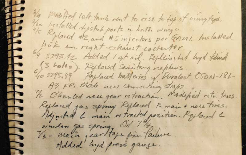
The 7/3 entry, which was made retrospectively, is incorrectly dated; it should be 7/9. But the important entry is the one on 7/2. The order of items reported is random -- they were done over several days -- and the cycling of the gear to adjust the retracted position of the left main was done before the right main tire was replaced. In other words, I did not cycle the landing gear after replacing the right mail tire. I didn't fly between then and the 9th, so the flight on which the gear failed to retract and the mainshaft taper pins failed was the first one with the new right-side tire. It now appears pretty clear that my theories about the problems having begun with the failure of the rivets in the left inboard door bellcrank were incorrect; the problem was simply that the tire is too large; everything else followed from that.
The tire is a retread, and is 17 inches in diameter. My old tires, which are Air Tracs and are worn out, are 16 inches in diameter. The tread depth on the new tires is 1/4", so the old tires were presumably around 16.5 inches in diameter when new. The difference would be inconsequential on any factory airplane, since they have larger tolerances, but things on Melmoth 2 are tighter and it's apparent that I'm going to have to find smaller 600x6 tires. Or I suppose I could machine a bunch of the tread off my new tires.
[August 15, 2015]
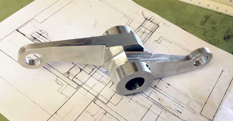
The aluminum bar in the picture below has now become this. It's not quite ready yet, and it's taking forever, both because our grandchildren are in town and my airport time is therefore somewhat curtailed, and because I'm not a skilled machinist and am working with a quite primitive milling machine and a very limited array of cutting tools. Once I've put the finishing touches on this part, however, I will be able to put the mechanism back together and see how badly whatever dimensional drift has occurred has thrown the whole system out of rig.
[July 22, 2015]
This is where things stand, or lie, at the moment.
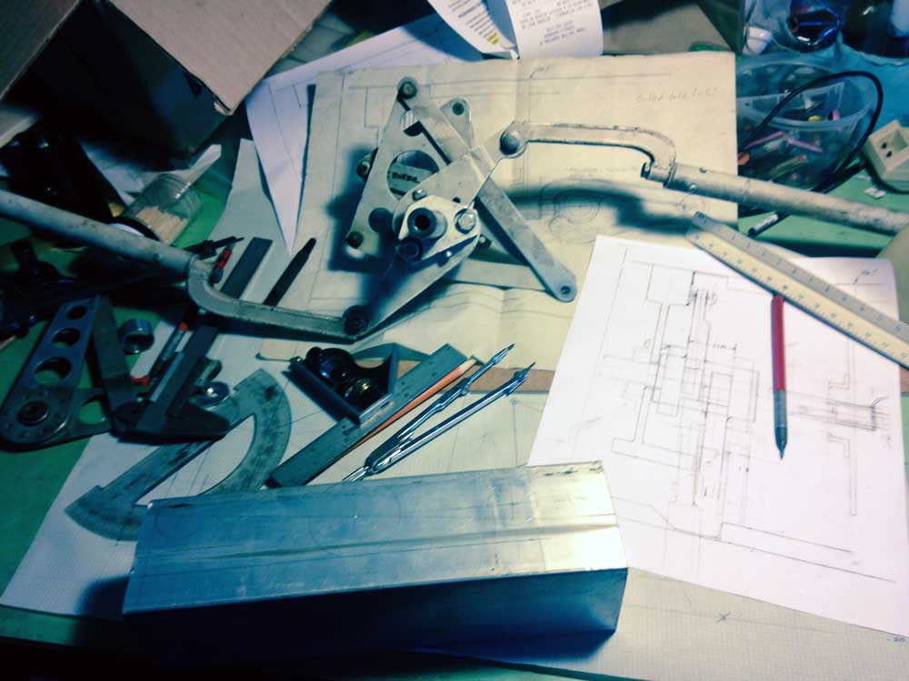
The partially deconstructed central actuator for the landing gear is in the upper center of the picture. The arms that retract the gear, and go overcenter to hold it up, can be seen, along with the rods that connect them to the retracting trusses. In the original design, each arm was bolted to a hub which was pinned, with one of the now infamous taper pins, to the 3/4" central shaft. The present scheme is to replace the two hubs and two arms with a single piece machined out of the 7075 bar in the foreground. Since the piece is asymmetrical in two axes, the most critical task is to ensure that I do not inadvertently make a mirror-image of what is needed, as I have done so many times before.
[July 16, 2015]
I got a chunk of aluminum of exactly the alloy I wanted -- 7075-T651 -- and exactly the size I wanted -- 2.5 x 2.5 x 8 -- for exactly the price I wanted -- $18 -- from the wonderful Burbank Metal Supply. From this billet I hope to carve a single piece that will replace four pieces in the earlier version. I have a new main shaft, this time 4130 rather than mild steel. I intend to replace the taper pins with 1/4" NAS close tolerance bolts. A couple of people have suggested that the taper pins, by failing, protected the rest of the system, like fuses; but I think I would prefer to have a system that the hydraulic actuator cannot break.
Here is an interesting plot of the loads, mostly tensile, on the links in the retraction system. The one labeled "Master" is the force from the hydraulic actuator, and suggests that an actuator force of less than 500 pounds (the analysis ignores friction), which corresponds to an hydraulic pressure of 400 psi, is needed to retract the gear. "R truss", "L truss" and "N truss" are the links from the main shaft cranks to the right, left and nose retraction arms respectively. The "trunnion" loads are in the links between the retraction trusses and the struts. The horizontal axis represents 120 degrees of rotation of the main shaft.
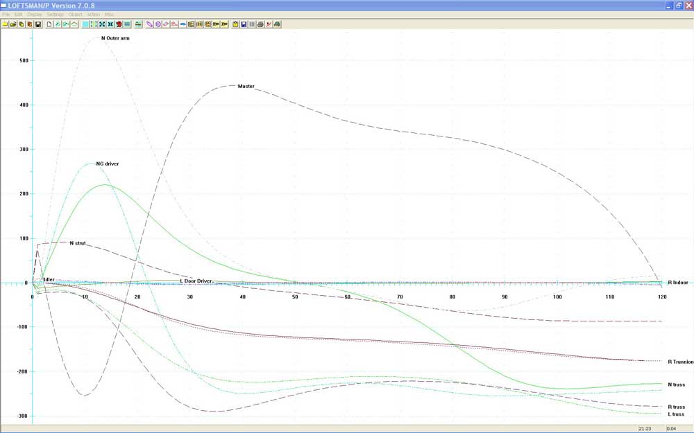
[July 13, 2015]
With six hours of work and the indispensable assistance of a mini gear puller that my neighbor John Biggs lent me, I managed to get the landing gear retraction main shaft out of the airplane. It turns out that the taper pins securing both the right and left actuator arm collars to the shaft had failed. not just the right one; in fact, the shaft was spun about 45 degrees with respect to both those parts. When I have freed those parts from the shaft I will work out a plan for repairing the damage. This experience has given me a poor impression of taper pins, and I am thinking about replacing them with close tolerance bolts. The main shaft may need to be replaced; I need to check the holes to see whether any plastic deformation took place. Here is the shaft with the two spun collars still in place; the two holes at the right end secure the crank to which the main hydraulic actuator is attached.
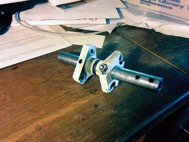
[July 10, 2015]
My understanding of what happened during yesterday's gear glitch was wrong. I still don't understand what really happened or why it happened. Some forensic engineering and stress analysis will be required to puzzle it out, and some ingenious disassembly work, the details of which I have yet to figure out, to repair it. Two 1/8" rivets in the bellcrank operating the left main gear inboard door had indeed failed, and so the door was not opening to allow the left main gear to retract. But the much more fundamental problem is that a steel taper pin, which connects the central driving shaft of the gear retraction system to the retraction linkage for the right (not left!) main gear and the nose gear, sheared. That was the loud bang that I heard.
This raises several questions. One, what caused it to fail? Was it a fault in the original machining and assembly? Or was the joint subjected to excessive stress? If the latter, what stress level was expected, and why was the pin not strong enough to withstand it, several times over? The second question, or class of questions, has to do with how to repair it. Because of the way the mechanism is assembled, the main shaft -- a 3/4" thick-wall steel tube -- has to be freed from the aluminum arm to which the failed taper pin attached it in order for the whole assembly to come apart. It's not yet clear whether or not the sheared surfaces are clean enough, and sufficiently flush with the outside of the steel shaft, to allow it to slide inside the aluminum arm. If not, the only option I see at the moment is to take a Sawzall to the shaft and then make a new one. Obviously, I don't want to do something hastily and later realize there was a better way, so I'll be thinking about this a lot during the weekend.
At the same time, I'm resurrecting the computer program that I wrote in 1991 to design the kinematics in the first place in order to study the torques and tensions in the various parts. I hope with it to be able to see what the stress levels in the failed pin should have been, and why they were evidently greater -- or the pin weaker -- than expected. The whole assembly is quite inconveniently situated in a six-inch-wide cavity between the main spar and a closed torque box. In the two pictures below, the missing large end of the taper pin is visible as an empty hole in the first image, and the threaded small end can be seen, from the opposite side, in the other.
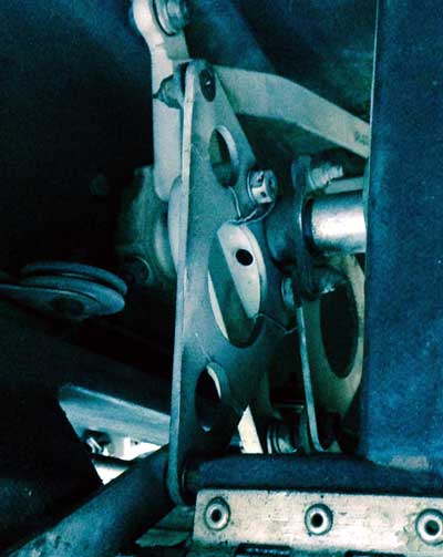
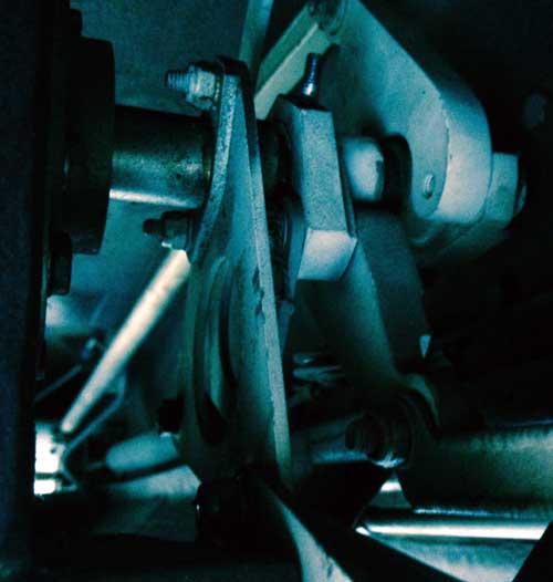
[July 9, 2015]
The small adjustment that I made to the geometry of the left main gear retraction arm had the unexpected effect -- doubly unexpected because it had worked fine on jacks -- of making the inboard door interfere with the tire and prevent it from fully retracting. The tire jammed against the door today in flight, failing a bellcrank in the door's actuating linkage. Here is the geometry at approximately the point where the collision must be taking place:
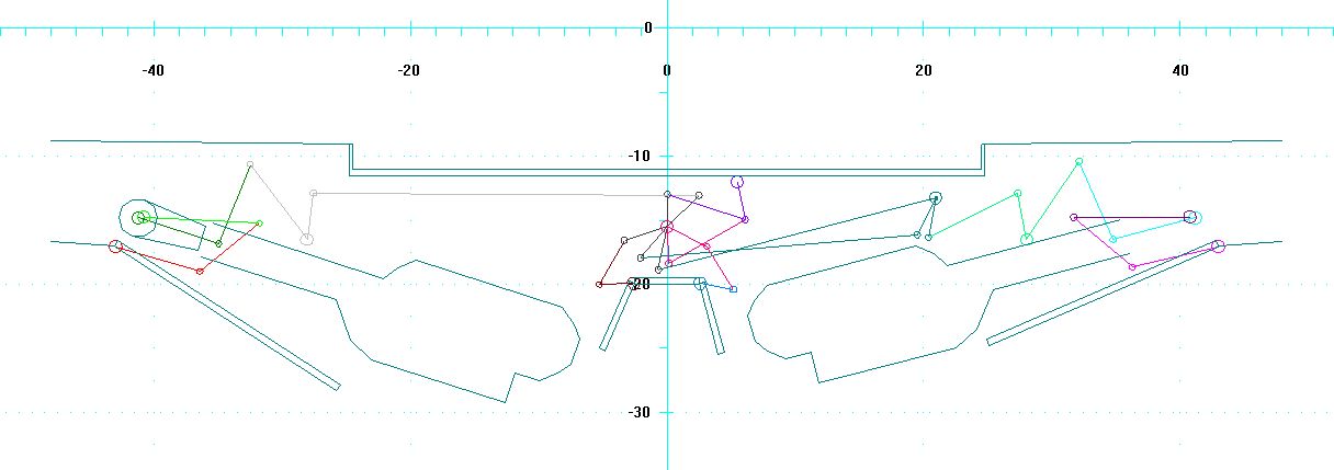
It's apparent that the left door gets closer to the tire than the right one does. The linkage that controls it is quite complicated and while I can't remember why everything is just the way it is -- I designed it in 1991 -- I do remember that I could not find another way for it to be, although I was obviously interested in keeping the door as far from the tire as possible. There is already a relief in the door for tire clearance; I may be able to make it deeper. First, however, I have to repair that bellcrank, this time with four rivets rather than two. A rivet failing makes a noise like a gun going off. The first time it happened was in flight; I though some major part of the gear system might have failed, in which case one strut might collapse on landing. I landed as gently as I could, and it turned out everything was fine; none of the major components was damaged, and the gear went down and locked as it was supposed to. The second rivet failure took place on jacks, while I was trying to figure out what had happened the first time. Now I know. I need to make an external switch for cycling the gear from outside the airplane; when I cycle it from inside I can't see what it's doing.
[June 30, 2015]
Someone asked why the gear doors are not adjustable, like those on every other airplane. Actually, both the upper door, the one that hinges to the bottom skin of the wing, and the innermost door, which hinges on the underside of the fuselage near the centerline, are independently adjustable, as are the nosewheel doors. The only ones that aren't are the big semicircular doors that cover the upper half of the tires. The reason they aren't is that the wing is small (105 sq. ft.) and although the profile at the root is 18% thick it was impossible to fit the 600-6 tire and strut into it without the strut (which is on the outboard side of the tire) grazing the wing contour when retracted. Consequently, the semicircular doors sit right up against the strut and cannot be adjusted inward.
Another person asked whether it is not possible to make a nosegear free-drop into place. The answer is that it is, and would be highly desirable, but it is possible only if the wheel retracts forward. On a single-engine plane with a tight cowling, fitting the nose tire under the front of the engine is difficult. The Cessna 210 manages it with a somewhat deeper cowling than mine; I tried to find a way and failed. Actually, now that I have a new gas spring installed I think the gear will free drop and lock, provided the indicated airspeed is 90 knots or less. It certainly locks on the jacks.
[June 29, 2015]
One of the results of doing things in an unconventional way is that you learn why the conventional way is preferred. It was out of a desire to simplify my hydraulic system that I decided to use a single central hydraulic actuator and also a single central landing gear up-lock, and to connect all three gear legs mechanically. I have had to modify that system in some ways -- for instance, the nose gear has a gas spring and a hydraulic actuator of its own to help it go down against its own aerodynamic drag -- but the solid interconnection among the gear legs remains and has for an unintended consequence that it is very difficult to make small adjustments in the behavior of individual legs. For instance, the only way to adjust the height of the retracted wheel in the well, and therefore the fit of the wheel covers, is to move a hole in two small aluminum lugs on the retracting arm -- which is to say, make the lugs over again. The kinematics program that I wrote to design the retraction linkage in the first place said that to raise the left main wheel 3/8" I needed to move the hole in question .040", or 1 mm, upward. I made the new pieces last week and today installed them. To my surprise and great satisfaction, the left main is now in the proper position when retracted and the doors are flush. I decided, however, that the bolt that connects the gas spring to the retracting arm was not well enough supported, and so I took the system apart again and made an additional steel part that will have to be welded into place before I reassemble the nose gear and get the plane off the jacks.
[June 22, 2015]
I was wrong to say in the previous entry that the nose strut gas spring had been installed upside-down. As is apparent here, it was installed shaft-downward, as it should be. I was misled by the fact that it had a journal bearing at the bottom end and a self-aligning bearing at the top. It seemed to me after I dismantled it that the journal must have been at the top if it was anywhere, but I was mistaken. Today, at any rate, I decided it would be better with self-aligning bearings at both ends, so I modified a spherical-bearing rod end to replace the journal. Today I also re-installed the nose gear retraction linkage with shims made from some .0025 stainless steel sheet that Dick Rutan gave me years ago, and I mounted two new tires, the nose and the right main, on their respective wheels. It's remarkable how much heavier a new retread tire is than one whose tread is worn out. Now that the nose retract arm pivots are tight again, the linkage is going to have to be readjusted, along with that of the sagging left main gear. The new gas springs are supposed to arrive on Thursday, so I hope to have most of this stuff taken care of by the end of the week. I have not yet tried to cycle the flaps.
Peter Lert pointed out to me that McMaster-Carr sells a complete range of gas springs (or gas struts, as I gather they should be called; I keep calling them gas springs to distinguish them from the landing gear struts). I don't know why I didn't think to look there, other than that when I searched for the part numbers of my old springs on line McMaster-Carr was not among the vendors who popped up.
[June 19, 2015]
I put the airplane up on jacks to swing the landing gear and replace the gas strut in the nose gear, which did not do its job of forcing the gear down against the airstream during the double malfunction of June 6. Gas struts lose their moxie over time, and this one had been in there for 12 years. I had probably hastened its enfeeblement by mounting it upside down. The longevity of gas struts is enhanced by mounting them with the rod downward. I probably did what I did because the rod ends it came with worked best that way. At any rate, the gas strut, which is supposed to have a force of 100 pounds, now has only 45. Finding a replacement is going to be a problem, because I can't find its part number in any of the online catalogs; I guess I'll put the old one back in for the time being. I was able to find replacement parts for the gas struts that hold the windows open; they too are getting weak, and I'm getting nervous about a gust of wind slamming a window on my fingers.
I found that one of the pivot bolts securing the retracting arm to the airframe was somewhat loose, so I took the whole apparatus apart to inspect it. The 5/16" holes in the anchor weldments are oversize by several thousandths, I don't know why; I hope to be able to fix the problem by inserting some very thin shim stock.
Some time ago, when I recorded the cycling of the landing gear with a small camera attached to a boarding step, I noticed that the left-side gear doors hung down a bit, and I wondered about the right-side ones, which could not be seen. On the jacks, the right doors close more or less perfectly. Having all three gears mechanically interconnected has some advantages, but ease of adjustment is not one of them. Correcting the 1/4-inch sag of the left main gear requires making a minute adjustment to the geometry of the retracting linkage. In the past I have made these adjustments by remanufacturing certain parts, moving a hole by maybe 20 thousandths of an inch, because doing it the easy way, by screwing a rod end in or out, would have the unintended effect of setting that gear leg slightly off vertical when lowered. I am wondering, however, whether it really matters much whether the gear legs are perfectly vertical. It's really just a visual thing, and for that matter sometimes they don't look vertical even when they are.
I have not even gotten around to the flaps yet. I'm hoping that bleeding them again will not be as big a job as it was the first time, because the hard part, the fluid in the lines between the master and slave cylinders, would not have been affected by the massive leak.
[June 12, 2015]
I got two Duralast batteries at Autozone to replace the two Yuasas. I decided to try the Duralasts because they are readily available off the shelf. They are identical in size to the Yuasas, but the terminals are slightly different -- just enough so that I had to replace a couple of the copper fittings I use to connect the two batteries to one another and to the airplane. An irritating thing about them is the size of the openings at the tops of the cells. They are so small that it is impossible to tell the fluid level by eye or, for that matter, even to remove the plugs with anything less than a pair of pliers. I suppose I will have to get a glass pipette to check fluid levels. (I chose the open cell type because the sealed "maintenance-free" version, besides being more expensive, has a different terminal configuration. If I had known that I was going to have to re-do the connections anyway, I might have gotten sealed ones instead. They have about 25% more cold cranking amps.)
Incidentally, the failure of the Yuasa was my fault; I had let the fluid level get too low.
Once the new batteries were in place and charged, I tried to retract the flaps, which were still extended a few inches, as they were all during the return flight from Paso. Nothing, but the sound of the hydraulic pump was uncharacteristic. Checked the hydraulic fluid level. Empty reservoir. Looked under the wings and fuselage. No leaks. Removed the floor under the rear seats, knowing full well what I would find: a big pool of hydraulic fluid, and a line that had popped off its connection to the retract side of the right wing root actuating cylinder.
That explained the failure of the flaps to operate and the gear to lock down, even though I had 28 volts from the alternator. The gear initially retracted because there was still fluid in the reservoir and lines. The gear circuit is separate from the flap circuit, so the leak did not affect it. But then, when I tried to retract the flap, most of the fluid ran out. When I lowered the gear for landing there was evidently just enough fluid left to release the up locks, but not enough to push the nose gear all the way down against the airstream and lock it. Since all three gears are mechanically interconnected, if one does not lock, none do.
What is surprising to me about this sequence of events is that two significant failures could occur at essentially the same time but, as far as I can tell, independently of one another. I can't see what the batteries have to do with the hydraulic plumbing. Besides, the connection that came apart was not even in a high-pressure part of the flap system; it was a line that supplies pressure to push the flaps back up. That takes almost no force at all; in fact the air rather pulls the flap forward. There is, however, a pressure spike when the flap reaches its up stop; I suppose it's most likely that the hydraulic failure had already occurred earlier in the day, when I retracted the flaps after landing at Paso.
Like everything, this has been instructive. For one thing, it's evidently time to get a new gas spring for the nosewheel; the one that's in there is 12 years old and didn't do what it's supposed to do, namely help the gear lock down. For another, I learned to be cautious about saying, "But what's the chance that X and Y -- two improbable events -- will both happen at the same time?" The chance may be small, but it's not an impossibility.
June 6, 2015]
I went to Chuck Wentworth's annual Antique Aero invitational barbeque at Paso Robles today.
When I tried to start the engine for the return trip, there was a moderately loud pop and the starter ceased to turn over. At first I thought something had broken, but after some discussion with Mike Melvill, who was there too, suspicion moved to the batteries, since after the failure the aircraft voltmeter was reading just 8 volts. I checked the batteries separately with a handheld voltmeter; one read 12.4, which is expected, the other 10.4, so that was obviously the bad one. The sound I heard must have had something to do with the failure of that battery, but I don't know what. Do batteries make a sound when they short? Anyway, the problem's onset was sudden: voltage readings and cranking power had been normal when I started at Whiteman in the morning and the electrical system had been behaving well for a long time.
One of Chuck's employees, whom I know only as Shannon, brought over their start cart. The plane started normally. As I taxied toward the runway, however, the system voltage kept dropping. Evidently there was insufficient field voltage and so the alternator was not charging. I tried to operate the flaps and nothing happened, so I figured it was a lost cause and taxied back. When I was in the taxiway approaching Chuck's, however, the voltage began rising rapidly and soon was at 28; evidently the field kicked in or I was taxiing at higher rpm. At any rate, I decided the alternator should be able to support the electrical requirements in flight, so I taxied back.
I again tried to lower the flaps, but they stopped at about four inches extension, I don't know why. I decided I would just have to see how the landing gear did in flight; if it would not retract I would return.
The gear did retract fully after I took off. The flaps, on the other hand, would not budge. That was a puzzle; the flaps should take much less power to operate than the gear. At any rate, I flew back with the flaps partly extended. I lost a few knots, but not many. The radios and other low-power services worked normally.
When I was six miles or so out of WHP I slowed to 100 knots and lowered the landing gear. It dropped, but did not lock down.
As I discovered a few years ago, because the hydraulic valves are closed-center it is actually possible to land even without the sway braces and drag links being locked overcenter. But I didn't want to take a chance, so I removed the acrylic window from the nosegear viewing hole (it's held in place with aluminum tape), opened the hydraulic bypass valve, pulled the gear breakers, put the gear handle in the down position and then with the aluminum pole I've been carrying around for 12 years against this eventuality I pushed the nose gear down and locked, as verified by the position of the big torque tube in the cockpit that connects all the gears together. When the nosewheel locks, the mains automatically lock as well.
The landing was uneventful.
I do not understand why the flaps did not operate even though the gear did, sort of. I do not understand why the gear went up but not down. Possibly there was still some power stored in the batteries when I took off, but raising the gear depleted it and flying for an hour did not restore it. The indicated voltage in flight was 28, as expected from the alternator, but the ammeter read zero, which means that the batteries were not taking a charge.
Question of the day: Should I replace just the bad battery or both of them, even though the other seems perfectly good? They are nearly three years old.
[June 2, 2015]
In another setback for dipstick calibration, I ran a series of tank volume analyses in Loftsman for a fuel depth of 4.38 inches at the dipstick and for several pitch and roll angles. Here are the results; roll angle is the horizontal axis.

So, while the quantity would be 12.7 gallons with the airplane level, it could be as little as 10.6 gallons with the wings tilted 2 degrees toward the tank in question and as much as 15.6 gallons with the wings tilted 2 degrees the other way and the nose pitched up 2 degrees. This seems to put paid to any idea of making precise measurements with the dipstick in the field. But since the purpose of the dipstick is not to measure fuel quantity before each flight -- the totalizer is supposed to take care of that -- but to get a precise reading from time to time in order to re-calibrate the totalizer, I can use a jack to level the plane in the hangar if it does not want to level itself. The saving grace of the errors is that the effects of pitch angle are rather small, and while those of roll angle are much larger (~1.1 gal/deg) they are linear across zero, so that the sum of the two tanks remains accurate even though the measures for each tank are wrong.
[June 1, 2015]
I drained the left fuel tank, which I had run pretty low, and put the fuel from it into the right. I then pumped fuel into the left tank, initially a gallon at a time and then at progressively larger intervals, up to 20 gallons, noting the dipstick reading after each addition. It was about the worst possible day to do it, warm, with a stiff breeze blowing, so that the fuel evaporated from the dipstick more rapidly than usual. Nevertheless, I collected a bunch of numbers which looked pretty random and strange until I got home and compared them with the calculated values. It turned out that they matched nearly perfectly, except for one. Unfortunately, that was the one for which I had jacked the plane up to a perfectly level attitude after returning to the hangar. It should have been the best match of all; instead, it was off by half an inch, or four gallons. To confuse matters further, the slightly higher wing at the fuel pump had been the left wing, and so the fuel depths I was measuring should have been larger than with wings perfectly level rather than smaller. Using the calculated calibration, I concluded that there was now around 7 gallons of fuel in the right tank, which was just what the totalizer said; but that didn't mean much, since I had set the totalizer on the basis of dipstick readings after the fuel spill of January 16. Still, any crumb of consistency is welcome.
[May 28, 2015]
It occurred to me yesterday evening that I should look at the EGT differences in terms of temperature rather than fuel flow, so this morning I printed yesterday's graph, drew a vertical line through peak EGT on the TIT (which I use to set the mixture) and then measured the temperature difference between peak EGT on each cylinder and the point where its curve crosses the peak TIT line. Given the imprecise nature of the data, the three right-side cylinders, 1-3-5, are at or within a couple of degrees of peak EGT; the three left side cylinders, 2-4-6, are richer by 8, 10 and 2 degrees respectively. The differences are inconsequential.
I ran the fuel in the left wing down to a couple of gallons yesterday; now I can drain it and then add a gallon at a time to calibrate the dipstick. I also need to install the landing light, although I don't have too clear an idea of how it should be aimed.
[May 27, 2015]
We got back from Cape Cod last Thursday, but one thing after another prevented me from going to the airport until today. The first thing I did was fly for an hour and a half and take another set of EGT measurements. The new #2 and #5 injectors have brought those cylinders into closer alignment with the others. This is what the sweep looks like now:
All cylinders peak within 0.2 gph of the average except #4, which is now the outlier at 0.3 gph. The interesting thing is that the left side of the engine (cylinders 2-4-6) is richer than the right. I suspect that this could have something to do with the 90-degree bend in the induction pipe just before it reaches the throttle body, but it would be hard to be sure because the injector flows have been fiddled with so much. In any case, they are now much better than they were after the intake manifold modification, and the engine leans beyond 100 degrees lean of peak while remaining perfectly smooth. When I finished the test I left the fuel flow at 7 gph, which gave 157 ktas at 10,000 feet density altitude and 22.3 nmpg. This presented a gratifying contrast with the Comanche 250 in which I learned to fly; it cruised at the same speed using 14 gph.
[April 17, 2015]
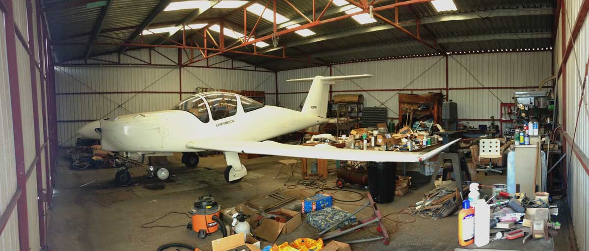
Leaving for a month. Til we meet again...
[March 27, 2015]
The dipstick handle now has two tiny (.047 piano wire) prongs with which to unscrew the access caps. I have but to calibrate the dipstick itself. I have a table of fuel surface heights versus volume, but I need to fine tune the relationship of the table to the dipstick and, for that matter, verify empirically that my calculation of fuel volume is correct. It was done in Loftsman by the typical digital approach of dividing the wing up into 1-inch wide slices, and then slicing these airfoil-shaped slices again into 1-inch wide columns and finding the volume of each one from the bottom inner skin to the fuel surface, and finally summing up this Giants' Causeway of avgas into one portable and compendious ocean. The accuracy of the dipstick depends on the airplane being level, which I can assure with the spirit level app in my phone; the surface of the wing centersection, under the front seats, is nominally level. I guess I should also do the volume analysis for a couple of fuel heights and pitch and roll angles, to get an idea of how sensitive the dipstick reading is to airplane attitude. Obviously, this is of concern mainly at low fuel levels, but they are the ones that are mainly of concern.
GAMI send me a couple of replacement injectors for my #2 and #5 cylinders, which are still the outliers. I installed them -- I'm getting quite good at it -- and in the next few days I'll do another EGT survey.
Digging around in my midden heap today for some 1/8" I.D. thin-wall flexible tubing with which to plumb my wake rake -- I didn't find any -- I stumbled upon a 20-inch piece of 1/4" auminum tubing, which I needed to complete the re-routing of the fuel vent in the right wing. I knew I had some somewhere. The price at Vista is extortionate. Twenty inches wouldn't have come to much more than Nancy's and my morning coffees and scone (which we share) at Fix, the trendy local espresso joint, but I hate to pay for something I feel certain I will find on the floor if I just walk around long enough with my eyes cast down.
[March 25, 2015]
I installed the dipstick ports in both wings. Although I originally thought each plug would have a built-in dipstick, I decided today to use a single, separate dipstick combined with a tool for extracting the plugs by means of the two small holes drilled in them. After fiddling with various materials I found that a narrow strip of the same carbon fiber material that I used for my wing spars shows a wet surface long enough to permit a reading. I will need to calibrate the dipstick and mark it with some kind of paint that can be applied with a fine brush. I have a calculated calibration, but I need to confirm it by filling a tank one or two gallons at a time. The wings actually hold 70 gallons each, but since the plugs are below the highest point it will not be possible to dipstick more than 45 gallons. I have never yet put that much fuel (90 gallons) in the plane and in any case the purpose of the dipsticks is not to check fuel quantity before every flight but rather to verify and if necessary reset the totalizer from time to time. In the past I have done this by attaching plastic hoses to the quick drains and measuring the fuel height; it is such an inconvenient process that I have not done it so often as I should. The dipstick will be much more convenient.
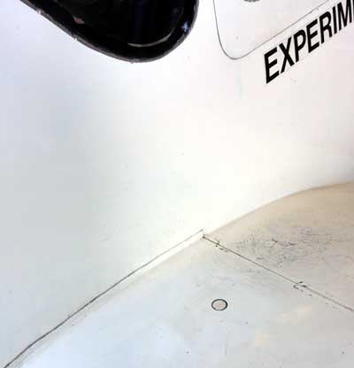
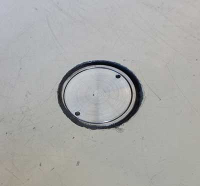
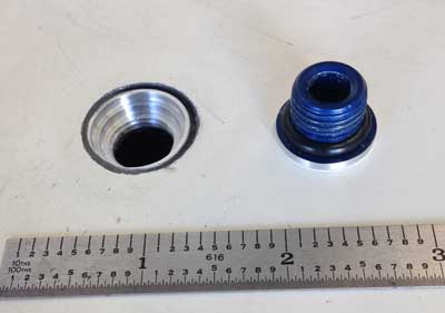
[March 20, 2015]
I have done a few minor things in the past week or two. I added a three-inch chimney to the baffle outlet on the #3 cylinder to see whether it affects the cooling at all. An NACA technical report says it will, and the test cylinder was almost exactly the same size as mine, but my chimney is only above the cylinder barrel, not the head, and so any beneficial effect may be imperceptible.
I machined a lot of material off the housing of the landing light, thereby reducing its weight by 1/2 pound.
I cut holes in the tops of both wing roots for the dipstick ports which my neighbor John Biggs is machining for me, but I have not yet bonded the metal ports into place. I did, however, measure the fuel levels through the holes, and it coincided quite closely with what the totalizer said. I had reset the totalizer after the fuel spill incident of January 14, using plastic hoses connected to the sump drains to ascertain the fuel levels.
Biggs also brazed four S-shaped 1/8" stainless steel tubes to a thin rectangular plate which I intend to tape to the top of the cowling behind the cowl outlets to measure the velocity of the emerging cooling air. I'm not sure how well duct tape -- the usual temporariy fastening method for aerial experimenters -- will hold up in a stream of 150-degree air, but in any case I can secure the wake rake to the cowling with safety wire so that even if the tape comes loose the rake will not fly back and gouge the windshield. I installed four 1/8" tubes passing through the firewall (in addition to a couple that are already there for measuring pressures within the cowling) and connected them to a manifold of four air valves that I got at Petco; it's intended for aerating several aquaria. This rig should enable me to ascertain the mass flow of air through the cowling -- which I already know to a good approximation, since I know the pressure drop ("delta p") and the relationship between pressure drop and cooling air flow rate is part of the published description of the engine. But it is always nice to see numbers from different sources confirming one another.
[March 6, 2015]
Now that I've messed up the cowling air inlet by providing it with strange ducts and ramps, I need to repaint it. The problem is, how to paint down inside those narrow, curving ducts. A paint roller about one inch wide and one inch in diameter would do it, but Googling "narrow paint rollers" brings no relief. Perhaps I could make such a roller out of a sponge and a wire hangar. I am a do-it-yourselfer, after all.
[March 5, 2015]
I did the tank vent modification on the left wingtip. I siamesed two 1/4" aluminum tubes together by bending an arc at the end of each and then cutting them off flush with the side of the straight part of the tube. The two bent ends mated neatly, forming a sort of gothic arch, which I sealed with JB Weld. I drilled in from the tip to a point close to the present vent, which I cut off at the outside surface of the end rib of the tank, working through an oval hole I had cut in the saddle between the wing and the upturned tip. I was then able to insert a short length of tubing through the portion of the vent tube that remained in the wing -- the old vent was 3/8" tubing, so the 1/4" tubing fits loosely inside it -- and pot it in place. After inserting the new vent through the drilled hole, I connected it using short lengths of Tygon tubing. Finally, I sealed and contoured the hole at the tip using an epoxy-microballoon paste and temporarily covered the hole at the inboard end with aluminum tape. Eventually I'll add a ply of cloth over it and refinish the scar, but not before doing the same mod on the right wing and flying for a while to be sure nothing is wrong with the venting.
[February 19, 2015]
Nothing done yet on the tips; I've been rebuilding a rotten kitchen counter. I did go flying today, however. Not a very nice day, very hazy, but calm and smooth. Since I was not going anywhere, I backed the power down to 24/2150, 50 LOP, with a fuel flow of 5.7 gph, or around 40% of power. At a density altitude of 6,000 feet, this gave a true speed of 137 knots, or 28 statute miles per gallon at 157 mph. I'm proud of those numbers, in a four-seat airplane with 3,000-mile range, although, to be honest, they are at about 900 pounds below gross weight. The cowl flaps were completely closed, so the exit area was 20 sq. in. Delta p was 4.1 in. H2O, hottest cylinder (#3) 380 F.
I discussed this unexpectedly good performance at low power settings previously, here. (In that case, I was at 14,500 ft. d.a. and the true airspeed for the same fuel flow of 5.7 gph was 157 knots, not 157 mph.) What I did not mention then is that it is not impossible that the parasite drag coefficient increases with speed. For instance, the faster I fly the more the landing gear doors tend to bulge or flex outward, presumably increasing the parasite drag coefficient. On the other hand, my performance prediction program does include a factor to cover that eventuality -- an empirical correction based on the assumption that the parasite drag of many components, notably the wings, is likely to increase with increasing angle of attack. The more likely cause of the anomaly -- which is only an anomaly in the sense that the performance of the airplane doesn't agree with the computer program -- is an erroneous assumption about specific fuel consumption on the part of the program. It thinks the sfc ought to be 0.514 at this low power setting; if it were 0.47 instead, the numbers would match. Can a TSIO-360 Continental, running 50 lean of peak at 35-40% power, achieve an sfc of 0.47? I don't know.
[January 31, 2015]
I spent way too much time thinking -- see previous entry -- about the question of where to put the vent outlet at the wingtip to ensure 1) positive pressure and 2) freedom from icing before Dan Fritz, an RC modeler whom I have never met but who is a good epistolary friend, gently pointed out that the vent line does not have to open at the tip. It's enough that it merely ascend to the tip; it can then drop back down to its present outlet, in a cavity with a non-icing NACA flush inlet in the lower surface just outside the tank. I'm embarrassed to say that this never occurred to me. If it had I might have thought at first that there might be some siphoning problem, but after a Gedankenexperiment or two I would have realized that while there is a scenario in which siphoning could occur, the possibility is sufficiently remote that the advantages of the "rising loop" vent clearly outweigh it.
[January 22, 2015]
After reflecting a little more upon the fuel venting issue I realized that the best solution might be to run the tank vents up the upturned tips. That would put them high enough that no likely amount of tilt would make fuel flow out of them. Fortunately, this would not be very difficult to do; at least I don't think it would. The question then is how the vents would terminate. Often vents stick straight down out of a fuelage or wing and are cut off at a 45-degree angle facing forward, so that a slight overpressure is supplied to the tank. The overpressure is not really needed, but it provides insurance against a possible underpressure due to the local curvature of the surface from whiuch the vent protrudes. You don't want underpressure because you don't want to do anything to impede the flow of fuel to the engine. I could have the vent open at the leading edge of the tip, but the problem with that location is that it would be susceptible to icing. An aft-facing vent at the tip would be staring right into the center of the tip vortex, which is a low-pressure area, so that may not be ideal either.
Don't bother me. I'm thinking.
[January 16, 2015]
Wednesday, the 14th, was a rather eventful day for Melmoth 2. I flew to Las Vegas to pick up a couple of friends and bring them back to LA. We were in the middle of the takeoff roll at North Las Vegas when there was a change in the engine sound and the manifold pressure began to fluctuate. I aborted the takeoff. On removing the right side panel of the cowling we found that a slip joint in the exhaust had parted. I had thought that the geometry of the system made that impossible, and so I had not installed the solid link between the pipes that is supposed to prevent it; I was evidently right for 11 years and a few months, and then wrong. A very friendly A&P, Lenny at EGA Aviation, tied the pipes back together with multiple loops of safety wire and we were on our way. With a nice 15-knot tailwind, we saw groundspeeds around 200 knots all the way to Whiteman, where we left the plane in its hangar.
Late that night, I got a call from the airport saying that avgas had been flowing out the front door of the hangar, and they had had to cut the lock to get inside. There they found the plane listing to port at a crazy angle and fuel running out the tank vent at the wingtip. They collected a bunch of fuel in a jerrycan before finally lifting up the wing and putting a support under it. I came back the next day to find a huge amount of what looked like kittylitter on the hangar floor; it's some sort of absorbent stuff that they use for fuel and oil spills.
This had happened once before, on the way to Oshkosh in 2006 or so. I stayed overnight in Prairie du Chien (which means Dog Prairie, as opposed to Prairie Dog) and in the morning came out to find the plane tilted and a huge fuel stain spreading over the asphalt ramp. That time I dismissed it as a freak event related somehow or other to heavy tanks and a soft strut. That was probably basically right, but this time I gave it a little more thought. The only scenario I have been able to come up with is the following. A couple of days before the flight, I had added air to the right main strut, but I had not been careful to match it to the left otherwise than by eyeball (ideally, there should be 2.25" of exposed piston on each side). On the trip from Las Vegas to LA, the back-seat passenger sat on the right side, and so I fed more fuel from the right tank than from the left. This left the plane somewhat left-wing-heavy and with a softer left than right strut. It looked normal when we closed the hangar, but perhaps the drop in temperature during the late afternoon -- the Prairie du Chien incident occurred at night -- caused the left side to settle a little more. Now, the wings have comparatively little dihedral -- 3.2 degrees -- and when there is a fair amount of fuel in a tank to begin with it does not take a lot of tilt to start the fuel spreading out toward the tip. Evidently, as fuel moved outward the left strut must have settled further while the right one possibly extended a fraction, and so more and more fuel flowed outward in a vicious cycle that ended with it reaching the vent and running out.
I have been thinking about ways to prevent a recurrence of this embarrassing and costly contretemps. One would be to take a piece of 1/4" wall, 1.5" I.D. aluminum tubing and divide it lengthwise to make two pieces that would fit up against the backs of the exposed pistons when the plane is parked. If you didn't notice the big red flags and took off with them in place, they would fall away. You would use them only when there was sufficient fuel aboard to produce the imbalance.
[January 8, 2015]
I measured the pressures in the upper and lower plena. Here is the summary of the results, including the corresponding data from 11/09, before the intake manifold modification.

Beginning at top left, the first two frames show raw pressures, relative to the aircraft static system, in the lower (inlet) plenum and the upper (exit) plenum respectively. The slight downward drift of the lower plenum pressures with increasing cowl flap opening is due to the diminishing resistance in the upper plenum. The marked concavity of the upper-side pressure curves, compared with the expected straight-line variation in outlet area between 20 and 80 square inches, suggests that some extraction effect may be taking place with intermediate cowl flap settings. This may be wishful thinking; no doubt an observer less eager than I to feel that reversing the intake manifold was not a complete waste of time might find some other plausible explanation.
The right-hand chart on the top row shows lower plenum pressure and available dynamic pressure, or q, against indicated airspeed. For some reason, nearly 100% of pressure is recovered at 80 knots, but only 86% at 140. Perhaps the cowling inlet flow is affected (adversely) by Reynolds number.
The bottom row contains three versions of the same variable, namely delta p, or cooling air pressure drop across the engine. The two on the right are the ones I showed on January 4, below, that is, the current measurements and a set taken in 2009, before I reversed the intake manifold and cleaned up the exit airflow. The left plot is the difference between the first two plots in the top row, that is, the upper-plenum pressures subtracted from the lower-plenum ones. In principle, it ought to be identical to the direct measurement of delta p (middle plot, bottom row). In fact, the results coincide nicely at 80, 100 and 120 kias, but the results for 140 kias are quite different. I don't know how to account for this, but I will continue to take delta p measurements in the future at cruising speed (which is usually around 140 kias) to see how they compare with these.
[January 4, 2015]
On the 2nd I collected better-quality data on delta p -- the pressure drop across the engine, and the primary determinant of cooling -- than I got last July after I reversed the intake manifold. It's interesting to compare these data with those from 2009, when I had neither uncluttered the low pressure plenum above the engine nor cluttered up the air inlet with weird ducts. Here are the two data sets side by side (the 80, 100, etc are indicated airspeeds in knots):

There is some imprecision in both data sets, because the cowl flap openings cannot be set exactly. I marked half-inch increments on the side of one flap, which I can see from the cockpit, but their setting is still only accurate to, say, plus or minus a tenth of an inch. Still, two observations about these data can be made. One is that the maximum delta p at 140 knots is now less than it was four years earlier. This could be due to energy loss in the inlet because of the guide vanes I added there. (The reason for those vanes can be found here.) This is a change for the worse, but at least it is at high speed, where cooling effectiveness is not an issue. I should note that the 1.5-inch opening is the largest used for climb; the 2-inch opening is used only on the ground because it provides no additional cooling in flight, but some additonal drag.
The other difference is that delta p is now consistently higher with partially closed cowl flaps. It would be nice to think that it is due to my having removed obstructions from the upper side of the engine. It may be that removing the transverse intake-manifold tubes, which impeded air approaching the exits, improved the aerodynamics of the cowl flaps in a way that is most noticeable in just a limited intermediate range of positions -- a "sweet spot". This is not implausible; the cowl flaps are analogous to a slotted flap, and the aerodynamics of such flaps is sensitive to slot geometry. I do think, however, that the difference, whatever the reason for it, is real, because it is too large to be accounted for by the uncertainty about cowl flap positions.
Next week I will collect data on absolute pressures in the high- and low-pressure plenums. I have the corresponding numbers from 2009. Perhaps they will shed some additional light. The delta p change could be accounted for by increased pressure in the lower plenum or decreased pressure in the upper one; increased pressure in the lower one is, frankly, unlikely.
[December 19, 2014]
A couple of days ago I finished off the layups in the fancy new -- but seemingly not especially effective -- cowling air inlet. My epoxy pump was acting up, so I mixed the epoxy using a balance scale I made years ago out of a few pieces of scrap wood and aluminum and a couple of nails. It works extremely well and is probably more accurate than the pump, which is long overdue for a cleaning. My epoxy is all out of date, but since none of these parts is structural that doesn't matter; it still hardens in the expected time and manner. Now I just have to paint the whole thing -- never my strong suit.
At the suggestion of Peter Lert I ordered an off-roader's running light to use as a landing light -- just pro forma, since I don't fly at night any more. Although small -- 5.5 inches long and maybe 1.25 inches wide -- it was incredibly heavy at 20 ounces. Most of this weight was for a heat sink with half a dozen massive fins. Since the whole thing draws only 18 watts, it's hard to see why it needs such an impressive heat sink. Perhaps it was adapted from an earlier product that used halogens, which give off lots of waste heat. In an effort to get rid of some of the weight I started cutting it apart, and in so doing inadvertently damaged a printed circuit. I ordered another one -- they're fairly cheap, $40 from JC Whitney -- and with what I learned while ruining the first one I think I will be able to machine away at least half the excess weight; the walls of the housing surrounding the lights are about 3/8 of an inch thick. I intend to attach it to the right main landing gear. It's rated for 12 or 24 volts, but I ran it for a while on a 28-volt power supply and it seemed happy enough.
I never get much done during the holidays, and these will be no different.
[December 10, 2014]
A basic measure of cooling efectiveness is delta-p, the pressure drop in cooling air flowing through the cylinder fins and baffles. Ideally, the baffles should block all air flow except through the cylinder fins, and should force air to flow equally over the front and back of each cylinder. In reality, there is some leakage through baffles, and not all cooling air is effectively used. Setting aside those losses, two factors determine delta-p: the pressure recovery in the high-pressure plenum, which in my case is below the engine, and the resistance encountered by air on the way overboard after having passed across the engine. The project of reversing the position of the intake manifold was intended to remove obstructions on the way out; the modifications I have been making to the cooling inlet are intended to reduce losses associated with air entering at high speed and coming to a halt in the plenum. Today I took a few measurements of delta-p that can be compared with ones taken prior to these modifications. There appears to be a slight improvement, but, considering the expected margin of error, it is insignificant.
[December 6, 2014]
As long as I was remodeling the cooling air inlet, I added a ramp in lieu of the vertical barrier, about 9 inches behind the inlet lip, where the front of the nosegear box/engine mount is. I flew yesterday for the first time with the new inlet configuration. The ambient temperature was lower than it has been in the past weeks -- 43 deg F at 10,000 feet -- and I have not collected CHT data systematically in the past, so I have only subjective impressions to go by, but the cooling seemed very good. The oil temperature was down a bit, but not as much as I'd like; still, it was down by more than the ambient temperature drop, so I feel pretty satisfied with the changes to the inlet. I can now set aside the hacksaw with which I was prepared to remove everything I'd added. Apart from making sure I had not dealt a fatal blow to the engine cooling, the purpose of the flight was to collect EGT data in order to evaluate the effect of changing the #2 injector. It looks at though #2 is still way out of line with the others. In fact, it looks worse. I wonder if the correction was accidentally made in the wrong direction. Next week I have a flight to Paso Robles that will give me an hour in which to collect another set of EGT data and also to get definitive delta-p measurements using the new inches-of-water gauge. Incidentally, it's very satisfying to press the rocker switch that controls the cowl flaps and see the delta-p gauge instantly react.
[November 15, 2014]
Back from the east late Wednesday, went Thursday to get my medical renewed, then by the airport to visit the plane. My pitot-static cert expired while I was away, so I won't be able to fly until I get that done next Wednesday. I was hoping to find the replacement injector for the #2 cylinder waiting when I arrived, but it had not yet come; they are running several weeks behind at GAMI, I hope because of a surfeit of orders.
While I was away I visited Randy Greene, an old friend who is CEO of Safe Flight Corporation; they make all sorts of equipment ranging from leading edge stall warnings to autothrottles and other such fancy stuff. We flew the company's 172, which is a testbed for their new angle of attack system. This is a completely revised version of the system in my plane; it uses different electronics throughout, although the leading-edge tab that serves as a flow condition sensor is externally similar to mine. The display, which sat atop the panel in the middle of my line of sight, consists of a stack of green, yellow and red lights. Randy and I have argued for years, nay decades, about the proper orientation of the display in my unit, which is an edgewise meter with a moving pointer. I feel that the instrument is essentially an attitude indicator; when the nose is high, the needle is at the top. He -- and unlike me he owns a couple of jets and is used to flying that sort of heavy metal -- sees it as a flight director; if the nose is going upward, the needle should go downward, meaning "put the nose down" or, alternatively, "your speed is too low." The new instrument takes my view of the matter -- as do other angle of attack displays now on the market -- but Randy has not conceded: The Safe Flight label on the side of the instrument was upside-down. I doubt, however, that that will be the case on production instruments.
Our flight in the 172, which was supposed to acquaint me with the use of the new display, mainly reminded me of how different the 172 is from Melmoth 2, which is practically the only airplane I fly these days. In my airplane, approaching at 70-75 knots, you have a fairly dynamic sense of your energy vector; in the 172, which seemed more like a helicopter, you don't. I felt that we were barely moving on short final, although we were probably only 10 knots slower than Melmoth. Control forces, especially in pitch, are also much higher than in Melmoth, and control responses much less crisp. In short, I was so preoccupied with the unfamiliarity of the airplane that I took no note at all of the AoA indicator during the final stages of the approach -- just where it is supposed to matter most.
[October 18, 2014]
The cowl flap mod was a complete failure. The cowl flaps still come to a halt 1/4 inch before closing at their trailing edges; evidently this is a function of air pressure on the aft portions of the cowl flaps overpowering the motor, not, as I had thought, distortion of the actuation geometry owing to internal pressure on the cowl itself. Now that the clutter on top of the engine has been cleared away it may be possible to revise the geometry of the cowl flap actuators to provide longer lever arms, but that won't help unless the travel of the jackscrew can be increased, and I don't think it can.
On Thursday of last week I collected a new set of EGT data. These numbers, while better than the last set, are still not entirely smooth, but they are a starting point for revising the selection of GAMI injectors to match the new flow conditions with the reversed intake manifold. Because there is more scatter among the EGT peaks than there used to be, I can no longer run as lean as I used to, and so my typical power settings for a given speed have changed. With the stock intake manifold and the standard set of GAMI injectors for my engine, I used to cruise, normally at between 12,000 and 15,000 feet density altitude, at 27 in. Hg and 2,300 rpm, with a fuel flow of around 8.6 gph and a true airspeed of 175 kt (20.35 nmpg). Now, with the mixture distribution somewhat messed up, I set up 26 in Hg and 2,350 rpm at 12,500 feet density altitude and began to detect roughness at 9.3 gph and 176 ktas (18.92 nmpg). Peak EGT at the turbocharger inlet came at 11.1 gph and 190 ktas (17.17 nmpg). I would rather be at 20 nmpg than 17, even though the price of avgas at Whiteman just dropped from $6 a gallon to $5.75.
One way to look at the EGT peaks is in terms of their offsets, in fuel flow, from the average, which is also the peak turbo inlet temperature. The numbers, going from cylinder 1 to 6, are -0.13, -0.53, +0.37, +0.07, +0.37, -0.13. In other words, for example, the #1 cylinder reaches peak at a fuel flow 0.13 gph leaner than peak TIT; it is therefore slightly richer than the average. The most egregious outlier is #2, and so the first step will be to replace it with a leaner one to bring it into better agreement with the others. Then I will do a new sweep and see what else needs to be changed.
[October 11, 2014]
During the past couple of weeks I've taken care of some deferred maintenance and made a couple of minor modifications.
I rebuilt the left outboard flap actuator, which had been leaking for some time with sufficient volume to leave a trail of hydraulic fluid down the underside of the wing. It took me a couple of rebuilds to get the one on the right side to stop leaking -- the design of the cylinder is admittedly defective -- and I hope that this one will now finally stop as well. I have not seen any fluid yet after several in-flight cycles (cycling on the ground, without aerodynamic loads, does not put enough pressure on the cylinder to reveal a leak).
I installed the EGT probe that I got on eBay. It works, but I have not yet done the mixture sweep that is needed to figure out how to rearrange my GAMI injectors to get all cylinders to peak closer together, as they did before I turned the intake manifold around.
I modified the sheet-metal chimney that conducts air overboard after it has passed though the oil cooler. I had used wedge-shaped ducts on both the inlet and outlet sides, but on perusing Paul Lamar's book on cooling rotary engines I noticed that more of an open plenum on the outlet side is apparently preferable.
I replaced the now torn aluminum tape with which I had sealed the gap where the left intake runner passes through the rear baffle with a gasket of sheet silicone; the tape on the right side is still holding together, so I won't bother with it for the time being.
I also began a little project that I have been intending to do ever since I put the final cowl flaps into place in 2006. In principle the trailing edges of the cowl flaps are supposed to close completely, but in fact, I think because bulging of the cowl under pressure slightly changes the geometry of the actuation system, they remain open about a quarter of an inch. This is inconsequential, and may even be beneficial, but I'm moving the travel-limit microswitch from the actuator itself to the cowl flap so that the motor will continue to run until the flap is actually closed, regardless of the pressure within the cowl.
[September 25, 2014]
I solved the problem of the inaccurate inches of water gauge by making a new dial, which I calibrated with my manometer and glued to the front of the instrument. I bought a used EGT probe on eBay; it came today, and I hope to get it installed tomorrow. That will make it possible to do a proper EGT survey and get the peaks for the respective cylinders aligned. George Braly at GAMI was shocked that I use an Alcor analog EGT instrument, and urged me to get a proper engine analyzer. I objected that they are rather expensive, and he replied that most pilots find that they pay for themselves in reduced maintenance costs. He forgot that I have almost no maintenance costs, since I do my own maintenance. I'm trying to stretch out my engine's life so that it and I die at about the same time, since there is no possibility of my being able to afford an overhaul.
While I'm on the subject of money, people sometimes wonder what it cost to built Melmoth 2. The answer is not entirely meaningful, since I already had the engine, instruments, hydraulic pump, and so on, and much of the carbon and glass fiber that I used was given to me; but my materials and services invoices for the 20-year construction period, which I kept for tax reasons, added up to $17,000.
Today I picked up Dan Raymer at Hawthorne and we went to Catalina for lunch. Both airports charge $25 landing fees. At Hawthorne I was at least able to land a second time to drop him off without having to pay again. I always thought Catalina was a special case; I wonder how many other airports have these fees, or will begin to have them. Needless to say, I won't be landing at Hawthorne again soon. Raymer brought along two floating seat cushions for the trip across the channel. Oh ye of little faith! But they are very light in weight and would certainly be preferable to treading water for a long time. My strategy for the 20-mile strait has always been to climb to 5,000 feet by mid-channel; that way I could glide to either side even if the engine were to fail at the worst possible moment. Really, however, one should worry more about engine failures over the city, where the chance of emerging in one piece is much worse.
[September 19, 2014]
I swapped the #1 and #3 EGT wires -- but not the probes this time -- back to where they started from. Now it's the #1 indication that's dead; so the problem is the thermocouple. And I tried out the new inches of water gauge, which turned out to be a huge disappointment; it's completely inaccurate, indicating anywhere from 35 to 50% higher than it should. I also observed that enlarging the outlet of the right-side inlet vane did not have much of an effect on the right-side CHTs, if any. Finally, I checked the induction air temperature while descending at low power and essentially no boost; it was 55 C, much lower than any in-flight oil temperature, and made me wonder whether my my breast-beating over forgetting which way the oil/induction temperature toggle was supposed to point was really warranted. I sink ever deeper into bafflement.
[September 18, 2014]
Although President Obama has taken some flak for saying that a basic principle of his foreign policy is "Don't do stupid stuff," I think that's a really pretty good rule. The problem is to tell what's stupid and what isn't. Sometimes when you're doing something stupid you're thinking it's smart. I suppose I set the bumbling bar pretty high with my confusion over the oil and induction air temperatures -- see the previous entry -- but just because you made one really big mistake doesn't mean you're done for the year. Here's proof.
For a while my #3 EGT indication has been kaput. When the selector switch hits #3 the needle drops over to the left as if poleaxed. The question is, what has failed? The candidates are the probe itself, the connections between the probe and the wires going to the instrument, the connections between those wires and the rotary switch on the indicator, the rotary switch itself, and, rather improbably, the wires themselves. I know the indicator is good because it works for all the other cylinders.
After procrastinating for a suitable period, I decided the time had come for action. So I swapped the probes between the #1 and #3 cylinders, along with their respective wires. Now, that was stupid. I hope someone reading this has to think for a few seconds before realizing why. All I did was move the problem from one cylinder to another. It's as if I heated the probe with a match, and then "tested" it by heating it again with a different match. Needless to say, the behavior was unchanged: when the selector hit #3, the needle keeled over. That was embarrassing, but at least it's over now. I did inspect the connections between the probe and the wires that connect it to the instrument; they were secure and the crimped connectors appeared sound. A little bit of insulation looked a bit scorched, but I didn't think enough to damage the wire. I wish I had had the presence of mind, while I was in the air today, to reach under the panel and wiggle the wire bundle connected to the selector switch. If there's a bad crimp or a loose screw there the needle might jump around a bit.
All of this is important to me because I feel that I can't lean as much before the onset of roughness as I could before I turned the intake manifold around, and the cause is almost certainly that the orifices of the GAMI injectors that worked on the stock manifold are no longer suitable for the reversed one, even though I reversed the injector positions along with the manifold. I need to get smooth, high-resolution EGT data for all six cylinders to see.
In the meantime, I bought an inches-of-water gauge on eBay. It had just a single port, so I added a second port for a reference pressure and sealed the case with epoxy. It will be a more convenient and accurate way to survey cowling pressures than my old water manometer was.
[September 13, 2014]
The areas under the right and left cooling inlet vanes are the same -- about 8.5 square inches each -- but the outlet on the right is about 10% smaller than that on the left. I hope that is the reason for the right bank of cylinders now running 20 deg C hotter than the left. Next week I'll raise the trailing edge of the right vane and see if that helps.
In the course of my months-long investigation of a rise in indicated oil temperature that occurred around December of last year, I compiled a list of all mentions of oil temperature in this document and also of any indications of what could have happened, or what I may have done, to cause the apparent change. The timing of the event was blurred by a period during October and November when the oil temperature and/or induction air temperature indications became intermittent. Both are displayed on the same instrument, selected by a toggle switch which, perhaps significantly, is unlabeled. When the toggle switch is to the left, oil temperature is displayed; to the right, induction air. (Induction air temperature is of interest because compression by the turbocharger raises its temperature significantly.) I always intended to label the two positions of this switch, but for varous reasons never got around to it. I believed, however, that the difference between the readings was obvious and so labels were not really necessary. Cleaning some connectors and repairing some frayed wires eventually cleared up the intermittent indication; I calibrated the temperature probes in the process and found them accurate.
Looking back over the history of oil temperatures going all the way to the fall of 2002, when Melmoth 2 began flying, I found a general pattern of temperatures around 90-110 C depending on flight condition (climb, cruise) and ambient temperature, until I installed the duct that isolated the oil cooler flow from the rest of the cowling. (The oil temperature redline is 116 C, but the desired continuous temperature is around 80 C.) I identified the high temperature of the air entering the oil cooler from below -- around 60 C, or 140 F -- as one of the likely causes of the high oil temperature. The exhaust pipes were evidently heating the air on the "cold" side of the cowling. After I installed the duct I reported that the oil temperatures were now where they were supposed to be, around 80 C. That was in February, 2010. In June I recorded an oil temperature of 88 C; the weather had warmed up a bit. Between then and 2013 I stopped mentioning oil temperature as an issue, but in a table compiled in May 2012 the oil temps appear all to be in the expected 80 C zone while the induction air temps are unexpectedly high -- 90 to 100 C. Over the years I had from time to time noted that the IATs were surprisingly high, and attributed that, somewhat illogically, to the way the probe was mounted at the dead end of the intake manifold, which is on the hot side of the cowling.
A few days ago it occurred to me to check another source of oil temperature data, namely photographs taken in flight in which the instrument panel is visible. In three photos taken between January and July 2011, the toggle switch is to the right; that is, it is displaying induction air temperature, which is 75 or so in the two pictures in which the gauge is readable. All this time, however, in my mind the default position of the switch was "oil," not "air." If I checked IAT at all, it was by switching the toggle to the opposite setting and then back.
Although the evidence is circumstantial, I now suspect that the rise in oil temperature in December of last year, for which no explanation or solution could be found, was not a rise at all; it was a change in the position of the toggle switch, resulting from the testing and calibrating that took place in November. That activity would have dispelled my apparent confusion -- suggested by the photographs in which the toggle switch is to the right -- over which toggle position was oil and which was air. The implication would be that IATs have always been in the 70-85 C range; that oil temps have always been in the 90-110 C range; and that seasonal variations in outside air temperature, and the contiguity of the two temperature ranges, tended to mask my confusion about which reading was which.
This is mortifying. I feel like an old lady who, finding a pair of expensive earrings missing, reports her housekeeper and gardener to the police, only later to find the earrings under her bed. If I am right, then the problem of high oil temperatures remains unsolved, but the supposedly sudden change in December of last year turns out to be a muddle, not a mystery. I humbly apologize to all those readers who took the time to think about the question and write with their suggestions.
[September 11, 2014]
I spent the first half of the week putting a vane into the right side of the engine cooling air inlet to match the one that I had put into the left. The one on the left side had lowered the temperature of air going into the oil cooler by 25 deg F, and had had the unexpected benefit of evening out the CHTs on that side. I hoped the one on the right side would have the same effect on the CHTs, and indeed it did, but it also pushed them up quite a bit, so that I saw 430 while climbing, which is unacceptable. (It was a fairly hot day, 94 on the ground, 55 at 11,500 feet.) The (slightly) hottest cylinder is now #3 rather than #1. It's interesting to see that relatively small changes in the inlet geometry can have such big effects on the CHTs; I just wish it were more obvious to me what needs to be done to get all the temps on the right side to come back down (other than just remove the vane on that side). The temperature rise across the oil cooler exceeded 90 deg F today; that is so large that it got me wondering whether the air outlet is too constricting and is slowing down the air going through the cooler.
[September 4, 2014]
Just to make sure that several previous checks of the functionality of the Vernatherm (which is supposed to regulate the oil temperature at 77 C (170 F)) were valid, I took it to Pacific Oil Cooler Service where they tested it and declared it okay. Not to be unduly easily persuaded, I asked them to lend me another one to try. They did. I flew with it today and found that it made no difference. At 8,500 feet, OAT 21 C, I was seeing about 180 ktas at 9.2 gph; the oil temperature settled at 110 C or 230 F. The seat against which the Vernatherm closes looks and feels smooth and undamaged. I will try to take a photograph of it tomorrow.
In the meantime I made the vane for the right side of the air inlet and also wrapped the exhaust pipes closest to the battery and the oil cooler intake duct with some sort of insulating stuff. One heartening observation was that when I was holding short for several minutes waiting for takeoff clearance, OAT about 85 F, the temperature of the hottest cylinder stabilised at about 160 C (320 F). The CHTs used to slowly climb and climb during long holds, so it may be that getting rid of all the obstructions in the way of the cowling air outlets actually did have a beneficial effect.
A reader wrote to tell me that the heat capacty of air is around one degree Kelvin per Joule per gram. Armed wth that information, I was able to do a quick sanity check on the heat rise across the oil cooler, based on the fuel flow and a general rule that around 8% of the energy in the fuel goes away through oil cooling (and 12% through cylinder head cooling). It came out to 70 degrees F, if I did the math right, and since the measured value is 80, at least it's in the ballpark. I was worried that it would be out by an order of magnitude, or maybe two.
I have probably confused a couple of people about this vane business. Here is a schematic sketch of how it works. The two drawings represent a cross-section of the left half of the cowling, seen from above, with the air inlet to the left. The top drawing shows how air entering the inlet separates from the rapidly spreading cowling sides and must then pass across the exhaust pipes (the three dark circles) to get to the oil cooler air inlet (the oval). The result is that the exhaust pipes heat the air before it gets to the duct inlet, and so the temperature of the air entering the oil cooler is 120 degrees F when the OAT is 75. The lower drawing shows how the vane directs a lot of 75-degree air along the inside of the cowling, where it is sucked into the oil cooler duct at a mere 95 degrees. I could make a closed duct in which the air would gain no heat at all, but I am operating on the assumption, or suspicion, that directing cool air along the cowling sides is beneficial in other, as yet undefined, ways.
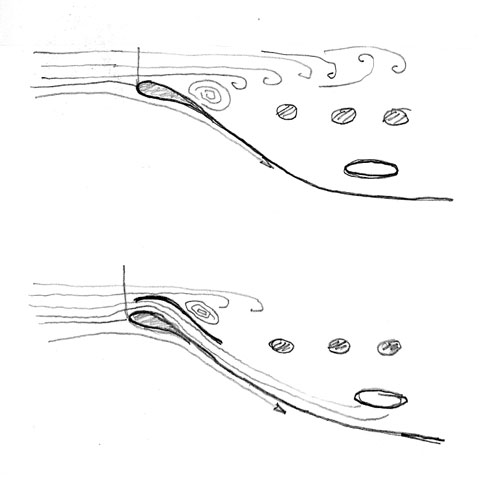
[August 20, 2014]
Readers smarter than I may have wondered how I came up with the "33% increase in heat transfer rate" in the previous entry. Actually, it should have been 40%. I don't know anything about heat, but my caculation is as follows. Without the guide vane in the cowling inlet, the inlet and outlet temperatures across the oil cooler were 120 and 180 degrees Fahrenheit respectively. With the vane, they were 95 and 175 (roughly). So the temperature rise was 60 degrees without the vane and 80 with. The inlet air temperatures are respectively 580 and 555 degrees Rankine (that is, above absolute zero), and the temperature rises represent respectively 10.3 and 14.4 percent of those values. 14.4 divided by 10.3 is 1.4, hence a 40% improvement. Does that make any physical sense? Outside air temperatures were roughly the same; I suppose that the efficiency of the cooler improves as the OAT drops and the temperature difference between the cooling air and the hot oil increases.
Since the boundary layer guide vane on the left side seemed to have a generally beneficial effect, I am thinking I may install one on the right side as well -- perhaps helping bring down the temperature of the #1 cylinder, which is usually the hottest -- and add some ramps to smooth the entry of the rest of the cooling air.
[August 18, 2014]
The boundary layer control vane in the cowling air inlet was, in a sense, a huge success. Initially at 7,500 feet, at 140 kias and 8.1 gph, with an outside air temperature of 70 F, the temperature of air entering the oil cooler duct was 94 degrees, with an 80 F temperature rise in the air crossing the cooler; the numbers had been 120 and 60 before, with an OAT of 75. I then descended to 4,500 feet, where the OAT was 81, and slowed to 117 kias with a fuel flow of 4.8 gph. Now the oil cooler duct inlet temperature was 102 and the rise 61. In spite of the 33% increase in heat transfer rate, however, the oil temperature was still 108 C at 7,500 feet and 97 at 4,500. Its remarkable stability suggests a new possibility: that it has been being regulated by the Vernatherm all along, the oil temperature has always been the intended 78 C, and the high indication is due to a fault in the wiring between the instrument and the sensor, which includes two connectors. This hypothesis would require an element of temperature dependence, however, since the oil temperature reads correctly when the engine is cold. I'm not sure it's really plausible.
One incidental and unexpected side effect of the flow diverter is that the CHTs of the three cylinders on the left side of the engine are now just about identical.
[August 14, 2014]
I will not get to test it until Monday, but I have installed a temporary vane in the engine air inlet. It's quite crude, but if the idea has any merit -- which is by no means certain -- even a crude vane will reveal it. It consists simply of a copy of the inside surface of the inlet, back to about 10 inches into the cowling, that is raised about an inch above the inner surface. In principle it would direct a sheet of air along the inner surface -- air likes to follow surfaces, provided that it does not have to flow "uphill" against rising pressure to do so -- and that air would be sucked into the oil cooler duct without having passed over an exhaust pipe or the turbocharger. Most of the pressure recovery -- that is, conversion of velocity into pressure -- of an inlet like this happens in front of the inlet, however, and it's possible that there simply won't be enough velocity in the directed sheet of air to make any difference. We'll see next week. Here's what it looks like:
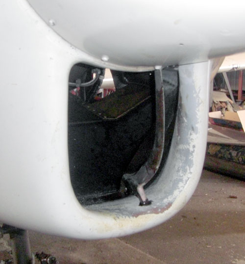
[August 7, 2014]
I have had a 1968 Chevy Malibu for 37 years. It has 450,000 miles (or somewhat more, actually, because the odometer stopped moving as it arrived at the last "50,000"). I am giving it to my son Nick, who loves it more than I do. It is somewhat threadbare, as everything I own tends to become, and he is having it fixed up at the shop of a friend of mine. This person lives in Jacumba, a tiny California desert town at the Mexican border. Fortuitously, Jacumba has a 2,400-foot gravel airstrip that is used for glider flying on weekends. There is a mountain at one end of the runway and the Mexican border is so close -- just a couple of hundred yards -- that you can fly on only one side of the strip; but it has a good surface. Yesterday Nick made the 3-hour drive to Jacumba in the Chevy, which we figure will remain there for a couple of years. I flew down to retrieve him. It was the first time I'd flown since getting back from Cape Cod.
At this point the reversal of the intake manifold has become sufficiently remote that my impressions are perhaps more objective than they were in the excitement of initial testing. My sense now is that nothing was gained in either cooling effectiveness or speed (yesterday it was 162 ktas at 7.7 gph -- about normal) whereas the change might have adversely affected the mixture distribution. It seems to me now that peak EGT is less distinct than it used to be and that the onset of roughness with leaning takes place earlier than it did before. I used to be able to lean to 150 LOP without any roughness; now roughness begins to appear around 50 LOP. I need to repeat the manometer and EGT tests that I did a month ago, and try to get better-quality data. Perhaps that would reveal whether I need to rearrange the GAMI injectors or get different ones.
It does seem that moving the throttle body to the "cold" side of the baffles may have improved the quality of the long-term idle at high temperatures, but extreme conditions occur so infrequently that I won't know for sure for a while. At any rate, that improvement hardly warrants the effort and expense that went into the change.
The oil temperature is still unacceptably and inexplicably high; it rose to 115 C during the climbout from Jacumba -- quite hot outside, and a steep climb to clear mountains -- and dropped to 95 in cruise at a low power setting. I will experiment with vanes to direct fresher air to the oil cooler duct inlet before resorting to the laborious and unwelcome extremity of adding yet another separate air intake to the cowling.
The gear retraction has become sluggish, and I am inclined to suspect the piston O-ring in the main actuator; but I need to get the plane up on jacks and be sure that the various bearings and links are all moving freely. Ars longa, vita brevis.
[July 31, 2014]
I got back from Cape Cod Tuesday at midnight. Yesterday I drained the oil, and finally discovered, after having this airplane for nearly 12 years and changing the oil I don't know how many times, how to do it without spilling a drop. The location of the sump drain just above the top of the nosewheel leg makes it difficult, and I've tried all sorts of awkward arrangements with funnels and tubes, both rigid and flexible. For some reason it never occurred to me to bend up a piece of sheet metal into a sluice to carry the oil backward past the strut and let it pour directly into a bucket. I should have asked my 21-month-old granddaughter Sasha for advice; she shows considerable mechanical aptitude already. I also serviced the flaps by adding a small amount of hydraulic fluid to the right-side circuits. In theory it should never be necessary to do this, but I haven't done it for several years, and that's a fair approximation of never.
[July 11, 2014]
I am leaving tonight on another trip for a couple of weeks. When I get back I'll see about putting some vanes into the cooling air inlet to keep some of the flow attached to the sides of the cowling. I also need to change the oil and re-align the flaps; today I noticed that at full flap the right flap was not extended as far as the left. There are four "bubble traps" in the system for this purpose. I have not opened any of them in a couple of years at least, so the system has been working fairly well.
[July 2, 2014]
I finally collected some pressure measurements inside the cowling. They were somewhat puzzling. For one thing, the quality of the data was not very good, and I'm not sure why; the data that I took with Hans Kandlbauer in 2009 were much smoother. It's pointless, perhaps, to compare data collected yesterday with those from more than four years ago taken by a person in the right seat with different parallax, etc. The old data suggested, however, that the pressure difference between the lower (high pressure) and upper plenums varies more or less linearly between zero and 1.5 inches of cowl flap opening (measured at the trailing edge of the cowl flaps) and also more or less linearly with speed between 80 and 140 kias, and I suppose I can use that observation to smooth out some of the scatter in the more recent measurements. At any rate, the upper plenum pressure seemed generally to have dropped by between 0.5 and 1.5 inches of water. This was what I was aiming for by removing the obstruction of the air outlets by the transverse portions of the intake manifold. So far so good. The lower plenum pressures have also dropped; this was to be expected, since, other things being equal, they are a function of the outlet resistance and therefore of the upper deck pressure. More surprisingly, the delta p -- the pressure drop across the engine, from the high pressure (bottom) plenum to the low pressure (top) plenum -- has also diminished. This is unexpected and I think must be due either to new leakage or to bad measurements.
I have developed a new theory about the high oil temperature. It is due to global warming. No, seriously; this has been a very warm winter, and earlier measurements were taken at considerably lower OATs. I have continued to monitor the inlet and outlet temperatures in the oil cooler duct, and observe the same 60 deg. F rise; but what is striking is how hot the air entering the duct is. It is actually hotter than air at the back of the engine, near the throttle. I thought that by placing the bellmouth of the duct below the exhaust pipes I was preventing it from ingesting pre-heated air, but looking into the cowling air intake yesterday I realized that if, as is quite possible, the flow is separating from the inner surface of the cowling behind the inlet, which expands much more rapidly than an ideal diffuser, the only way for air to get to the oil cooler duct inlet is to travel over the exhaust pipes first. I am toying with the idea of putting a vane in there to direct air along the lower inside of the cowling. I have thought occasionally about putting my little TV camera and some tufts inside the cowling to see what the flow in there is doing; now may be the time.
[June 25, 2014]
A recheck of the temperatures across the oil cooler confirmed a rise of 60 deg. F. What is surprising is that the inlet temperature is 120, the outlet 180, with an ambient temperature of 75. I have a chart of cooling air temperature rise for an IO-550 engine, and it seems that the air temperature rise is generally around one-third of the difference between the cylinder head temperature and the ambient air temperature. If that's any guide, the 60-deg rise seems about right. (The oil temperature, currently 210-220 deg F, is measured at the oil cooler outlet, so the oil in the cooler starts off hotter than that.) But it's the 120-degree inlet temperature that concerns me now. Why is it so hot? On May 12, 2012, when I measured temperatures at the future throttle body location (behind the engine, high up, on the cold side), I saw around 95 in cruise; this was at 14,000 feet, however, and the OAT was 43 F, so maybe the "cold" side of the cowling really is a steady 50 F above ambient.
[June 19, 2014]
A flight to measure the temperature rise across the oil cooler produced results that seemed surprising until I calibrated the Radio Shack probe in the new (brand name "RediChek") device and found that the old sender, while physically compatible with the new device, required a big correction. The correction curve turns out to be T = .77(t+23) in Fahrenheit. This obviates my observations of June 17 about the absence of a pressure gradient across the engine during cooldown; the corrected temperatures show the lower plenum to be consistently 40 deg. F cooler than the upper, even with the tail to the wind. When I got the plane out of the wind the difference was more like 70 degrees. That's more like it. The temperature rise across the oil cooler was about 60 deg F, which seems like less than it should be.
I collected another batch of EGT data, trying to be more careful this time, but there's more scatter in the new data than in the old. One difficulty is that the fuel flow indication increments by tenths of a gallon per hour, and so when it says 9.2 you don't know where you are between 9.15 and 9.25. The difference can have a significant effect on EGT.
[June 17, 2014]
Both of my Radio Shack remote barbecue temperature probes having ceased to work, I got a new one, this time with two indications ("food" and "smoker"). Fortuitously, it is compatible with the thermocouples from the old ones, so I can put four thermocouples in various locations and plug them into the transmitter in different combinations. Yesterday I made a short test flight with the oil filter (which is in series with the cooler) bypassed, just to make certain that the high oil temperature was not due to the filter being somehow blocked (though this would be extremely unlikely, since it has its own internal bypass valve). No joy there. I also tracked the temperatures above the engine and along the right side of the oil sump, where the fuel lines run from the fuel pump to the throttle/fuel controller. I wanted to be sure that radiant heating from the exhaust pipes was not affecting the fuel lines. That probe reported a balmy 80-90 F in climb and slow cruise (the OAT was 80 on the ground). What was interesting to learn, however, was that after shutdown the temperature throughout the cowling, below and above the engine, rose to a more or less uniform 200 F. I was parked facing downwind and so did not get whatever advantage might have been provided by a breeze on the air intake, but it was interesting to see that pumping due to hot air flowing out of the outlets -- cowl flaps wide open, of course -- did not create much of a temperature gradient across the engine. When I put the airplane into the hangar, maybe 10 minutes after shutting down, the expected gradient appeared. The last reading I got before turning off the temperature gadget was 180 below the engine and 220 above. Remarkably, the cowling shows no sign of deformation after 11 years of this abuse, even though Safe-T-Poxy is supposed soften at 160. Clearly it responds well to progressive heat treatment.
One place I would like to measure temperatures is across the oil cooler. In principle one would expect to see no temperature rise until the oil temperature hits about 170 F. At that point the Vernatherm valve should start to close, directing oil through the cooler and filter, and there should be an increasing temperature difference across the cooler.
My hangar neighbor Claude Morgan suggested I cut open the oil filter can to check for metal in the filter, on the theory that high oil temperature could indicate a hot bearing. I did, and didn't find any metal. It's time for an oil change; I'll get a spectroscopic oil analysis just to be certain.
[June 12, 2014]
After returning late last night from Boston, I did a flight today to try to pin down the EGTs, which in principle ought to reveal the effects reversing the intake manifold had on mixture distribution. I'll have to repeat this test more systematically, because this time I failed to record fuel flow, which ought to be the abscissa parameter, and also because the #3 (right middle) cylinder's EGT probe was not working. I also want to install a couple of air temperature probes to get the temperatures in the two plenums, and maybe set up my manometer to re-check delta-p (the pressure drop across the engine) as well.
I flew at 10.500 feet; the density altitude was 13,300. Power was around 27/2300, which represents an open throttle and open wastegate at that altitude (the wastegate duct diameter is small, and so there is some boost even with the wastegate open). My analog EGT gauge (Alcor, circa 1970) does not allow very precise measurement -- maybe 5-deg F increments -- and I was in a bit of a hurry, but here is what I got:

The top (blue) line is TIT -- turbine (or turbocharger) inlet temperature. It is hotter than the others because that probe is in a constant stream of exhaust gas, whereas the others just get a shot when the exhaust valve opens and then cool the rest of the time. (The initial steep rise is due to the fact that I started out using half-turns of the mixture control, then changed to quarter-turns.) The random fluctuations are presumably due to measurement errors; it might be useful to smooth the data mathematically to identify more clearly the peaks, but collecting the data more deliberately and carefully might help too. At least they all cluster within a half-turn of the mixture knob. Nevertheless, I got the impression that whereas I used to be able to lean to 75 or more LOP, I now start feeling roughness at 35 LOP or so. One thing I want to look at when I get the #3 probe working again is whether the cylinders on one side are collectively peaking before those on the other. I had some concern that this might occur because of the 90-degree bend in the inlet duct a few inches before the throttle body.
One striking thing that I observed was a steady 149 kias (183 ktas) at 8.8 gph. This is about 4 knots better than I would have expected, and implies that a not negligible drag reduction took place. Now, cooling drag is always the great unknown, and there are all sorts of wild reports about what a huge fraction of total drag it can be. It is very hard to believe, however, that cleaning some obstacles out of the flow path inside the cowling (where velocities are comparatively low) could reduce F (the "equivalent flat plate area") from 2.35 to 2.15 square feet. It would be nice to believe it, but I'm sure this gift will be withdrawn -- I'm sorry sir, that $10,000 was accidentally credited to your account -- the next time I fly.
[May 21, 2014]
An hour-long flight yesterday. I sensed a few subtle changes, but nothing dramatic. For some reason the EGTs on the individual cylinders seemed closer to one another than they used to, but at the same time I felt that peak EGT on the TIT, which I use for leaning, was flatter or less distinct than it used to be. These are contradictory impressions, but I was flying in turbulent air under a 4,000-foot overcast at low power (20/2100, 5.4 gph) and so those indications are atypical in any case. We're going east again for a couple of weeks on Sunday, but when we come back I'll do a systematic sweep at cruise power and altitude to map the EGTs against fuel flow and compare them with the ones I recorded ten years ago when I first installed the GAMI injectors. I will also collect data on pressure drop across the engine to see whether cleaning up the upper plenum had any effect.
The engine felt happy. CHTs were generally very low because of the low power. The oil temperature is still too high, but that's not surprising since I didn't modify those components other than to move the oil filter to a different location and replace the hoses to it with longer ones. Start was immediate and normal, so putting the fuel controller at the opposite end of the engine from the fuel pump does not appear to have created any problem in that department. After landing I inspected the engine and noted a slight fuel stain at one connection in the new stainless lines; the B-nut was not fully tightened. Otherwise, everything looked good.
It's possible that this whole manifold-reversal project will turn out to have been a huge waste of time, money and effort. It was fun, though, and I like the way the engine looks.
[May 20, 2014]
I made the turbo to throttle duct on Saturday by splicing four segments of aluminum pipe with laminations of Hysol epoxy, which can withstand the 200+ deg. F temperatures of the turbo discharge without softening. Today I used aluminum tape to temporarily close the gaps where the intake manifold passes through the baffles, and then did a 15-minute ground run with the cowling on. At one point I ran at high power until the hottest cylinder hit 200 deg. C (392 F). then throttled back to an idle. The CHT slowly dropped by 10 degrees or so. This is significant, because I believe that with the old manifold arrangement it would have continued to rise. I also did not sense any of the rough running that used to occur during long periods of idling; so it may be that clearing the cooling air outlet path of the obstructions created by the old manifold, and/or moving the fuel controller to the cool side of the baffles, has actually had an effect. It may also be that I am kidding myself; that tends to happen just after I have made some beneficial-seeming change. Unfortunately my remote temperature probe -- a Radio Shack gadget intended for grilling meat on a back yard barbeque while watching television in the den -- did not work for some reason, and so I did not get a reading of the temperatures in the environment of the new fuel lines. Tomorrow I will fly, weather permitting.
[May 12, 2014]
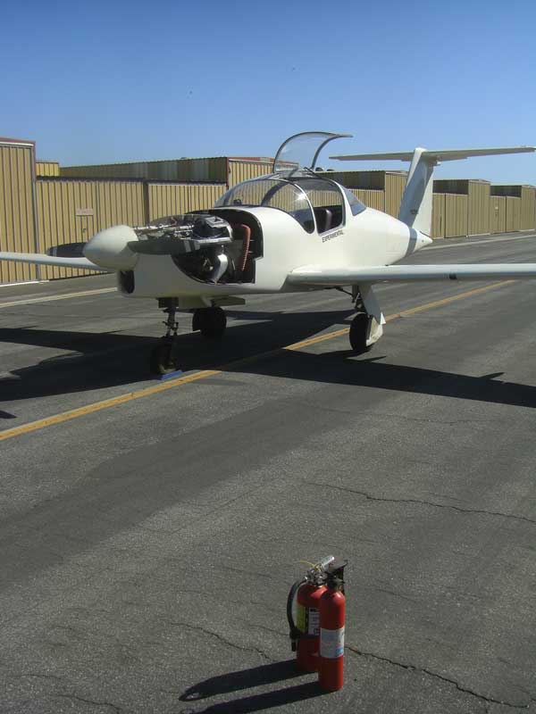
I ran a quart of so of fuel through the engine to check for leaks. There were none in the new plumbing, but there was a drip at a pipe thread fitting coming out of the fuel flow meter. That is a fitting that I have not touched during the current work, so I have no idea how long, or how much, it's been leaking. I suppose I can, however, congratulate myself on 1) not having burned up in flight and 2) having achieved such performance as I have achieved on a slightly lower fuel flow than I thought.
At any rate, I fixed the leak, secured a few loose ends, and put a temporary duct between the turbocharger and the throttle. I put all my tools away -- ritually signifying the end of a phase and the start of a new one -- and set aside the vast collection of nuts, bolts, washers, brackets, clamps, and so on that somehow had been made homeless over the last couple of months. I rolled the airplane out onto the taxiway, planted a couple of fire extinguishers in front of it, gave it a final looking-over, and climbed in.
After a good deal of geriatric coughing and sputtering it settled down and ran normally. I idled for a few minutes at 1,300 rpm, did a mag check at 1,700, and then shut it down. I looked it over carefully and found no oil or fuel stains. I need to replace various clamps and ties that I removed -- a lot of the wires and hoses behind the engine have been rearranged -- and do some more ground running, including a full-power run-up, before it will be ready to fly.
[May 9, 2014]
The stainless steel fuel lines are all in place. It turned out to be possible, as I had hoped, to run them close to the rear baffles so that they do not interfere with access to any part of the accessory case. They're quite difficult to bend, and once bent impossible to unbend, so I made each piece first out of aluminum tubing and then copied the dimensions and angles in stainless. This seems to have worked pretty well. To give myself a clear view of what I was doing, I took off the starter; after finishing the fuel lines I realized that they ran right through a bracket connecting the rear baffle and the starter adapter. I'll have to make a new bracket that somehow or other goes around them. I finished right at the end of the day, and had time only to pump some fuel through the system to check for leaks. There seems to be a big leak right at the fuel pump; everything else is dry. I'll figure it out Monday and then run the engine.
[May 4, 2014]
The plumbing for supplying upper-deck pressure to the injectors, fuel pump and magnetos is almost complete, and I managed to make all of it, so far, out of leftover tubing and fittings. I suppose at least part of the satisfaction I derive from finding re-usable materials in my junk-littered hangar is due to its confirming a belief, which underlies my reluctance to throw anything away, that some day even the most improbable scrap of stuff may come in handy. For the last piece, which is two feet long, however, I'm going to have to buy some 3/8" tubing, and it actually would not have killed me to use new tubing for the whole thing. I carom back and forth between extravagance and economy. A serial arachno-eksaeolist, I do blow out the spiders before re-using old tubing.
I found that I have a second tube bender for 1/4" tubing with a larger bend radius than that of the one I normally use; it works better for the stainless tubing, and I don't think I will need to fill the tubing with sand before bending it. That will leave, apart from some details like a missing lock washer here and cotter key there (of which I keep a careful list, since I would otherwise be certain to forget them), just the two fuel lines between the fuel pump and the throttle, and the big duct between the turbo and the intake manifold. The big duct continues to be a puzzlement; I can't find out who bends 2.25-inch .035 wall aluminum tubing. Even Woolf in Michigan, which specializes in this kind of stuff, apparently draws the line at .065, though if I spent hundreds of dollars on a special setup I suppose they might go thinner. Woolf specializes in extremely tight bends -- bend radius equal to tube diameter -- but for reasons of avoiding flow separation I would like to use the largest radii I can fit in the space. Apparently the best I will be able to do from them is a 180-degree 4-inch radius bend with .065 wall. Putting that together with various scraps from my heap, I will be able to assemble the required duct. It may be temporary anyway, because if I have not completely exhausted my appetite for modifications by the time this project is done the next one would be an intercooler that would replace most of this duct.
I like the look of the new plumbing; it's neater and more rational than the old. I hope it works.
[April 14, 2014]
I made a teensy bit of progress today on plumbing up the fuel pump before closing the hangar for a couple of weeks while Nancy and I go east to visit our progeny.
One reason that adding systems to a homebuilt notoriously takes as long as building the airframe is that there are so many decisions to be made about routing wires, hoses, air ducts and fuel lines. The present quandaries revolve around the two 1/4" stainless steel fuel lines joining the fuel pump and the throttle, which are at opposite ends of the engine. They will run alongside the oil sump (the underside of the engine being the cold air side) and snake their way up behind the rear baffles in such a way as not to compromise the accessibility of the magnetos, alternator, and so on, which is currently very good because I left a tremendous amount of space between the engine and the firewall when I first laid out the airplane. There are already a couple of steel hangers dangling from the sump bolts; these are the natural places to attach aluminum or phenolic blocks to secure the fuel lines. But it seems that while I'm at it I ought to include the 3/8" fuel supply and the 1/4" vapor return lines in the remodeling. Those lines are currently Aeroquip hoses, because they need to be flexible, but there is no reason they need to go all the way to the front of the engine; they could just go from the firewall to the back end of the engine, and continue forward as hard stainless lines. Or the hard lines could run from the firewall to the front of the enigne, with short flexible links to the fuel pump. That would make a neater and less bulky installation, but Claude Morgan, a hangar neigbor who in addition to being a retired UAL captain is an A&P, mentioned to me that it is preferred to run fuel lines above electrical wires, I suppose so that if a hot wire parts it does not fall down and short against a fuel line. That complicates matters further; there is no lack of wiring around the bottom of the engine. I suppose you could put firesleeve around the stainless lines, but that would somewhat defeat the purpose of using them in the first place. Maybe heatshrink would be sufficient. Plenty to think about while hiding the Easter eggs.
[April 12, 2014]
Now that the throttle cable problem has been dealt with, a new problem has come to take its place. The 2.25-inch SCEET hose that I had expected to use to connect the turbo to the intake manifold is unable to bend gracefully to the radii required; it wrinkles up inside like an accordion. I need to find some already-bent thin-wall tubing of 6 or 8-inch radius, or else find a tube bender who can make the stuff for me. The company that did the intake manifold bends seemed barely able to cope with material of .065 wall thickness; this ought to be more like .032 at the most.
[April 11, 2014]
The excess length of the throttle cable produced this goofy-looking arrangement:
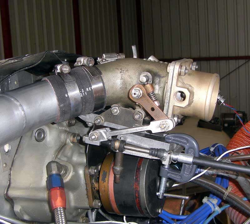
The C-clamp and cleco will be replaced by bolts securing a bracket that supports the fore (left, in the picture) end of the metal sleeve within which the push-pull cable slides. This sleeve is normally intended to pivot over a range of 20 degrees or so to allow attachment to radial arms like the lever on the fuel control; in this case, the link takes care of the misalignment issue and the sleeve needs to be held still to prevent random variations in throttle position, to say nothing of the possibility of locking overcenter at full throttle. (In this picture the throttle is at idle.)
The light tan-colored duct bolted to the back end of the throttle body is where the air duct from the turbocharger attaches. The threaded boss on its near side is for an air line that goes to the injectors, the magnetos and the fuel pump to provide them with turbo discharge pressure. The little dark nubbin visible through the hole is the induction air temperature probe, which enters through a similiar boss on the opposite side. It is aligned with the throttle butterfly, and so the aerodynamic disturbance it creates will not, I think, matter. The throttle body sits on an aluminum rail and is stabilized laterally and vertically by a thin steel plate anchored to the two upper vacuum-pump studs. The forward end of the rail is bolted to the engine baffles at a point close to where the baffles are secured by an accessory-case stud. The point of all this is to prevent vibration of the throttle body, and the whole setup is, as John Thorp said of my first airplane, "built like a brick shithouse" -- that is, stouter by far than the intended use requires.
[April 9, 2014]
The throttle cable turned out to be a problem. It is 3 inches too long, because Morse cables, or at least McMaster-Carr's Morse cables, come only in 1-foot increments, and it turns out I need a 21-inch one. Furthermore, the dimension from the anchoring groove to the threaded end was different from that on the previous cable, and so I had to make new hardware for connecting to the quadrant and the throttle. For the time being I am going to use a sort of trailing link to connect the engine end of the Morse cable to the throttle control arm, but sooner or later I will no doubt find out where to get Morse cables made to a custom length.
The throttle support is now in place and feels pretty good.
[April 2, 2014]
The reassembly of the engine compartment is progressing, so far without any major problems. The rear baffles are back in place, split now so that they can be removed in spite of the intake manifold passing through them. I will need to come up with a way to seal the clearance between the baffles and the manifold; split fiberglass flanges, laid up in place, are my current favorite candidate. I re-installed the Sky-Tec "lightweight" starter, which is indeed lighter than the original Delco, but not by much, and am keeping my fingers crossed, since it has not so far covered itself with glory. I am working now on the support for the throttle body, which does not weigh much but needs to be kept from jiggling around. After that I will install the new throttle cable and arrange the routing of the turbo-to-throttle air duct and the new oil lines.
I anticipate that the final step will also be most difficult: routing the stainless steel fuel lines between the fuel pump, the throttle and the fuel distributor. In 2004 I moved the distributor, which used to sit on top of the engine, to the front, below the propeller, where it is in the intake airstream and is not heated by the engine. It, the throttle and the fuel pump formed a tight group near the front of the engine, joined by a few short lines and hoses. Now, with the throttle at the rear, it's necessary to duct fuel twice the length of the engine, from the fuel pump back to the throttle and then from the throttle forward again to the distributor. This is straightforward for three-quarters of the way, but gets tricky when the two fuel lines pass behind the accessory case, since you don't want them to interfere with access to the magnetos, alternator and so on. I intend to mock them up in aluminum, which is much easier to form than stainless, run the engine to make sure everything works properly, and then copy the aluminum lines in stainless.
We're going to Connecticut on the 15th to visit our son and his family. I was hoping to get this project finished before we go, but with taxes needing to be done -- I do my own -- as well as various other preparations, I'm starting to have my doubts.
[March 26, 2014]
I finally got the intake manifold tubes back from the welder today and installed them. The top of the engine is now distinctly less cluttered than it was. Here is the previous setup:
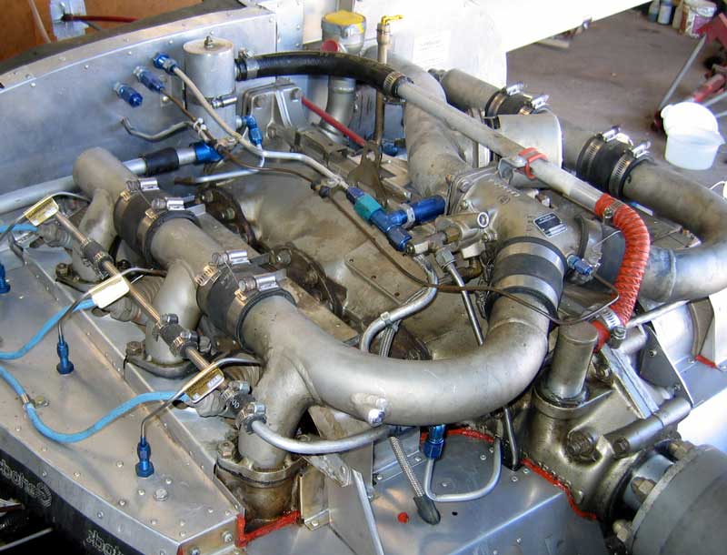
And here is the new one:
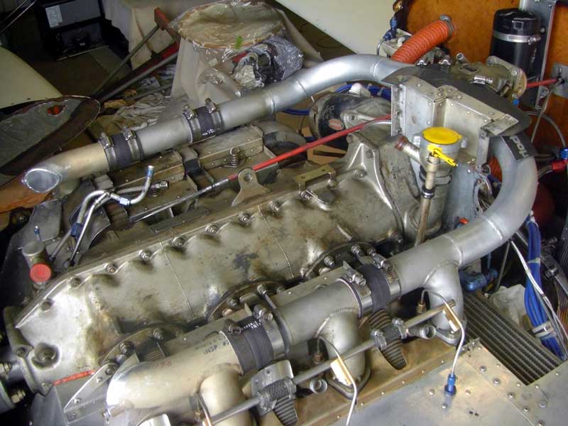
The only things that will be added are the tube running from the breather at the front of the engine to the oil separator on the rear baffle and a line running from the throttle body to the two injector shroud rails. It should be easier now for cooling air to find its way to the outlets at the front of the cowling.
The next step is to revise the rear baffles so that they split around the intake tubes, and then to install the fuel lines and the air lines that supply upper-deck pressure to the injectors and the fuel pump. Finally, the oil filter, which has moved to the right side of the firewall, will need new, longer hoses, and I'll replace the turbo oil scavenge line just because it's old.
[March 19, 2014]
The chalice of jury service passed before me, but being present at jury selection for a multiple murder trial was its own reward. Despite all the praise one hears of the jury system, I got the feeling that in difficult cases a just verdict would be a matter of chance. The occasional ruthlessness and mendacity of prosecutors are notorious, but to judge from what I saw on Monday their obtuseness should more than compensate. On the other hand, the common thread linking the prosecution's many peremptory challenges seemed to be any evidence that a prospective juror was capable of nuanced thought. The judge, Robert Perry, seemed amiable, balanced and intelligent. I was grateful for his light-heartedness, but the citizen beside me at one point leaned over to whisper that she thought it inappropriate to the gruesome crimes being tried.
I got the S-ducts back from the welder on Tuesday and today spend four hours making a fixture for welding them to the two rearmost elements in the existing manifold. It's still not finished. I always marvel at how many unforeseen complications conspire to stretch out the time things take, and yet I never factor them into my estimates. I guess that's what makes them unforeseen.
I told the welder that the welds in the duct segment did not need a lot of penetration, but he must have forgotten, because there's quite a lot of roughness on the insides of the joints. I ordered from McMaster-Carr something called a "ball hone" with which I hope to be able to take away at least some of the crud in the curved portions. The straight segments are accessible with an ordinary drum sander. The roughness may not matter much; the average speed of the airflow in the manifold is only about 70 mph at cruise (100+ at takeoff), and the throttle messes up the flow in advance anyway.
Once I have the new ducts bolted to the engine, the next difficult step will be to make up a fitting to attach the throttle body to the accessory case in order to support its weight. The rest is mainly a matter of reassembling the baffles and making new fuel and air pressure lines between the throttle and the fuel pump. That seems now as if it ought to be comparatively straightforward, but no doubt it will bring along its own retinue of unforeseen complications.
[March 15, 2014]
The tubes are at the welder's, and I've taken everything off the top of the engine. Unfortunately I have jury duty next week but with luck I will be sent home as unsuitable for making any serious decisions.
[February 28, 2014]
The tube bender delivered me four 170-degree bends of 5-inch radius. Two were good, with no rippling on the inner surface; two had some rippling. But since I need only two, I will use the inferior ones for practice. Here one has been sawn into the three segments that will be welded together to form the somewhat sinuous duct from the Y-shaped throttle body to the log manifold over each bank of cylinders. Part of the spare throttle body I got on eBay is visible, upside-down, on the right side of the picture.
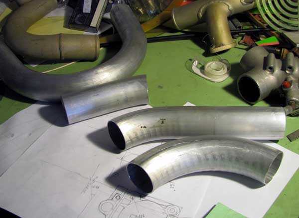
The first difficulty that arises is that the cross-section of the tubes ceases to be round in the bends. The outer surface is stretched and the inner one compressed, with the result that the inner one not only grows thicker but also pushes the middle of the tube outward. This is typical:
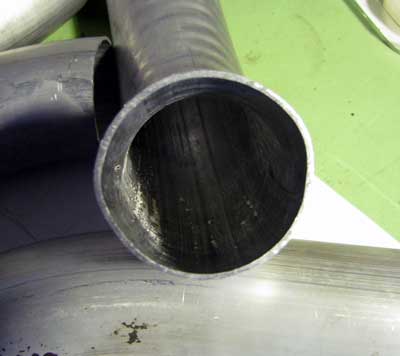
The mismatches are not too bad when segments are joined in an S curve in a single plane, that is, with a rotation of 180 degrees; but when you rotate one 90 degrees with respect to the other, as I will be doing, you are matching the widest dimension with the narrowest. I am not sure how to correct this problem, but I suspect that like many other problems it might be solved with a few judicious blows of a hammer. I will see on Monday. The aim is to get as smooth a duct wall surface as possible, and so it would be nice if the inner contours matched.
Surprisingly, the dimension between the centers of the intake ports on opposite banks is uncertain. My ancient and disintegrating Continental installation blueprint says the manifold runners are 21 inches apart and the intake ports 24.24 inches apart. That would make the offset from a runner to a port 1.62 inches. I have carefully measured the two manifold segments that I have (and which I will saw up to incorporate into the new manifold) and the offset is 1.70 in., which would put the intake ports 24.40 inches apart. Eighty thousandths doesn't sound like much, but when you're trying to bolt metal parts together it's prohibitive, and resorting to the hammer solution is not advisable. Fortunately, the ducts converge on the throttle at an angle of about 49 degrees, so if I tool up for the large dimension and it turns out to be incorrect when the parts are moved from the jig to the engine, I can trim off a small amount and move the throttle body forward slightly.
[February 25, 2014]
A small setback: The aluminum tubing ducts that I had designed to connect the intake manifold runners to the throttle body turned out not to be within the capabilities of the highly experienced tube bender who is doing them. There was not enough "tangent" between curved segments in different planes. I had a feeling that might be the case, but I hoped he would have some magical way of grabbing the tubes in spite of their being bent every which way. Apparently not. Instead he will make some U-shaped bends of 5-inch radius and I will cut them apart and have them welded back together in the required twisted-S shape. The wall thickness is .065, and I hope that the weld penetration can be sufficiently shallow to prevent much roughness forming on the inside of the tubes. I got the new throttle cable, for which I will need to make a new hole in the firewall. I have all the necessary parts for the intake manifold and am steeling myself to start sawing them up.
Incredibly, McMaster-Carr, from whom I have been buying a lot of stuff lately, charges about $60 for a 6-foot length of 2-inch OD .065 wall 6061-T6 tubing; I got an 8-foot length from Industrial Metal Supply in Sun Valley for $26, which included tax and an $8 cutting fee, the standard length of one "stick" being 20 feet. Industrial used to be a couple of miles east of where it is now, and it used to stock a lot of surplus sheet, plate and extrusions in aircraft alloys, 2014, 2024, 7075 and so on. That was when Lockheed was still operating nearby. The first Melmoth was build entirely of aluminum bought at $2 or so a pound from Industrial. Those days are gone, or almost; there is still a small, very nice metal dealer that stocks those alloys a bit east of where Industrial used to be; but the quantities and variety are not what they were in what I -- not the owners -- consider to have been Industrial's heyday.
[February 10, 2014]
I cautiously sent the WLR (world's longest reamer) a few inches into the piano hinge this morning, rotating and pushing it by hand. I observed that what collected between the flutes was mostly black muck, presumably composed of congealed grease, aluminum oxide, and airborne particulate matter of various species. I also observed that the lithium grease with which I had smeared the hinge pins was quite viscous. I accordingly cleaned off the pins and lubricated them with, of all things, 3-in-1 oil. This had the effect of reducing the "bump" in the elevator travel to a fraction of what it was before I began this process a month ago. I think that in order to ream the piano hinge -- I understand the objections to this process that several people have raised -- it would be best first to remove the elevator and to clean out the two sides of the hinge separately. Now that the friction is so diminished, however, I may not be very strongly motivated to do that.
I have been trying to establish the best position for the throttle body above and behind the engine. I had decided to use double-wall SCEET tubing between it and the two runners of intake manifold, but realized today that SCEET is not sufficiently flexible to make the necessary bends without wrinkling up accordion-fashion on the inside of the bend. So it will have to be aluminum tubing, which at least will have the advantage of stabilizing the assembly laterally.
[February 7, 2014]
Today the world's longest reamer was assembled by my neighbor, who machined a stepped V-block out of a piece of steel bar stock and then brazed the .098 reamer to the 6 foot long .095 shaft. I will give it a very tentative and cautious try next week.
I received this picture of the Rutan Catbird attached to an email today:
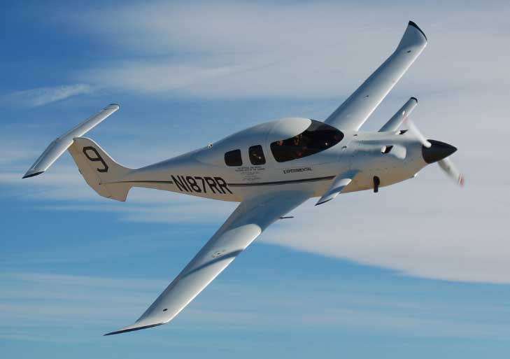
I was struck by the many resemblances to Melmoth 2: T tail, high aspect ratio low wing with similar planforms and upturned tips, bubble-style canopy, cooling air vents on top of the cowling and near the front. Like Melmoth 2, it is a 200-hp airplane using Roncz laminar sections for the wing. My first thought was that I must have unconsciously copied all these features. I then checked the dates and found that the Catbird was designed, as a potential Bonanza replacement for Beech, about five years after Melmoth 2 was. Although Rutan and I had many contacts, I don't recall much discussion of my design, then in the early stages of construction, and in any case it would be fanciful to imagine that Rutan would be influenced by me. It is more likely that we had discussed some of these features in general terms, or they were just in the atmosphere at the time. For example, Rutan had used top surface air outlets on other designs but had placed them farther aft. I thought the idea of moving them forward into a region of lower pressure was mine, but I guess it must have been a pretty obvious variation on the theme. He had certainly made clear to me the value of wingspan, something Melmoth 1 sorely lacked. Some significant differences between the two airplanes are the canard surface on Catbird, the fact that it is a 5- rather than 4-seater, and the fact that it was intended to be pressurized, although I don't think the pressurization was ever implemented. I'm not sure whether Catbird has flaps; at a certain point Rutan started arguing against flaps, having observed that he never landed on anything but paved runways at least 3,000 feet long. Personally, I have found the Fowler flaps on Melmoth 2 to be one of the more satisfying aspects of the design, but I'm not sure that would be a sufficient justification for putting them on a commercial product. On the other hand, I wonder whether Catbird could possibly meet the FAA's 61-knot stall speed requirement for single-engine airplanes; Melmoth 2 does so easily.
[January 31, 2014]
I did both cold and warm compression checks today and also inspected the bottom plugs. The plugs in the four front cylinders were dry; those in the rear two were slightly damp. All were clean and medium to dark gray in color. I don't know why the two rear cylinders should be different from the others, but at any rate there was nothing alarming about the plugs. The cold compressions were 74 - 79 - 78 - 75 - 80 - 74 and the warm 77 - 76 - 76 - 76 - 78 - 75. (The engine has 1,324 hours, and more than 35 years, since new.) Driving home from the airport I was wondering if you could dream up a figure of merit for compression tests -- something like the average divided by, say the square root of the largest difference. Never mind, I decided. At any rate, the compressions seemed acceptable and did not suggest that there would be a lot of blowby, so the reason for the rise in oil temperature remains a mystery.
[January 28, 2014]
I had the Vernatherm -- the thermostat that controls the oil temperature by forcing oil to flow through the oil cooler once it has heated up -- tested by Pacific Continental Engines. It seems to be okay. One of their guys came over to inspect the seat against which the Vernatherm closes; it is okay too. He suggested that excessive blowby on a cylinder could cause elevated oil temperature, and that engines that have been stored a long time and suffered some corrosion in their cylinders could be prone to this. He didn't know it, but my engine had been stored for 20 years while I was building the airplane. He suggested doing a warm compression check and borescoping the cylinders to look for "glazed" areas where the hone pattern has been completely polished away. I have done cold compression checks from time to time and found all of the cylinders to be in the middle to high 70s; I'm not sure how a warm check would compare with a cold one, but I suppose it would be worse because the oil would be thinner. We'll see. He also suggested that when I reverse the manifold I ought to add a balancing tube between the closed ends of the right and left intake runners. That has been suggested before, and I think Continental says it doesn't do anything.
[January 23, 2014]
I replaced the oil cooler with the refurbished one -- quite an operation, taking parts of three days, because of all the baffling surrounding it. Unfortunately, the change had no effect; the oil is still as hot as before.
I found a throttle body for my engine on eBay for $40; it will make it easier to make various parts for the reversed intake manifold without having to ground the plane for a long time.
I had been noticing for some time that my landings were getting worse. Melmoth 2 is a very easy airplane to land smoothly, and there is no reason every landing should not be a perfect greaser -- you should barely know when the tires touch. But I had been putting it down with a definite tap-tap, and I became aware that I was flaring with a series of small jerks -- these were not my passengers; they were wrist movements -- rather than a smooth motion. The reason for this turns out to have been not advancing age but hinge friction. Merely lubricating the hinge pin made a big difference; today I was able to flare with a smooth motion and grease the landing, in spite of a turbulent final approach and a quartering tailwind.
The plan of sending a reamer down the elevator hinge bore has been getting generally bad reviews from correspondents. Each person has a different view of why it will not work, however, so at least there is not one obvious objection. With all this naysaying, I can't resist giving it a try. I always remind myself of the advice of my skydiving jumpmaster at Harvard, John Leibacher, now an astronomer in Tucson, who, when I explained that I wanted to build my own plane and had been reading everything I could find on aeronautical engineering, said, "You can't build an airplane out of a cookbook!"
[January 20, 2014]
Dave Ganzer of AeroVironment, who probably knows a good deal more about this than I do, wrote to warn me that reaming the hinge bore would not work, because -- if I interpret his explanation correctly -- the problem is probably a large-scale bend in the hinge. I am assuming that it is local waviness. I used a straight, rigid fixture for bonding the hinges in place when I built the stabilizer and elevator -- this was in the 1980s -- but I failed to realize how large the clearance between the hinge bore and the hinge wire is, and so my very straight, very rigid fixture did not compel the hinges to be as straight as it was. I now realize, 30 years too late, that I should have used .098 drill rod, rather than .088 hinge wire, between the hinges and the jig. At any rate, I have ordered all the materials for the reaming operation, so I may as well give it a try.
[January 17, 2014]
My old friend and fellow airplane mess-arounder Peter Lert suggested, in an email rather alarmingly entitled "Redneck reamer", that I rough up the end of a hinge wire with a file or Dremel and send it down the hinge bore with an electric drill. I decided, however, to give the high tech solution a first try. My neighbor John Biggs, who is a skilled welder and machinist, thought he could weld a reamer to a piece of drill rod with the requisite alignment, so I am going to get an .098 reamer and a six-foot length of .095 drill rod and see whether that combination can clean up the hinge bore if sent through it very carefully, with frequent chip clearance.
[January 10, 2014]
Swapping the oil temp probes had no effect, as I expected, so I took my spare oil cooler to Pacific Oil Coolers in La Verne, about half an hour's drive from here, to be cleaned out and pressure tested. They found a cracked hold-down lug and wanted to sell me a new cooler, which would be $650 or so, on the reasoning that welding the lug and re-machining the gasket surface would cost $500. I asked them to clean out the cooler and return it to me with the cracked lug, which I'm sure I can get welded, and re-machine myself, for $20, if not for free. They readily agreed. For an experimental airplane, I don't need the official yellow "return to service" tag.
In the meantime I decided to do something about the increasing friction in the elevator hinges. The elevator is connected to the stabilizer by a continuous piano hinge that's about ten feet long, with a five-foot hinge wire inserted from either end. When I built these parts in the 1980s, it was difficult to perfectly align the piano hinges, which are bonded and riveted to the surfaces, over a distance of 10 feet. I came close enough that the pin could be inserted fairly easily, but there was a resistance "bump" in the middle of the elevator travel where the misalignment is worst. The pins had not been removed or lubricated for 11 years, and I suppose they had gotten dirty. It turned out to be very difficult to get the left-hand pin out; it finally moved after being doused with oceans of WD-40 and encouraged with a hammer. The right-hand pin slid out easily. I cleaned and greased the pins and re-installed them. It would have been better to remove the elevator entirely and clean out the hinges, but that's more of a process than I was willing to face that day. The friction is much reduced, but the resistance bump is still there. This got me thinking about whether there is some way to send a reamer down that long tunnel and shave away some material where the misalignments are. The hole in the extruded hinge is .098 in diameter, and the hinge pin is .088, so there is not a lot of beef there to work with.
[December 24, 2013]
Since some point in the not too distant past the oil temperature has suddenly been up around 95-100 C rather than the expected 78. My first thought was the Vernatherm, a thermal valve that shuts off a bypass duct in the lubrication system, forcing oil through the oil cooler. I'm not sure how a Vernatherm can go wrong, but apparently they sometimes do. I took it out and put it in a pan of boiling water; it got 5/32" longer, which sounds about right. Later I consulted a nearby A&P, who said 1) I should use oil for that sort of thing; 2) the point is not just to see if the Vernatherm grows, but to find out the temperature at which it starts expanding -- or reaches its maximum length, I forget which; and 3) I should try to remember the last thing I did to the engine before this problem presented itself. Unfortunately I do not keep a log of engine parameters on each flight -- I should -- and so I could not pinpoint when the oil temperature had gone up, but that did remind me that back in the middle of November I had fiddled with the oil and induction air temperature probes and had probably swapped probes in the process. So before I start tearing into the oil system I guess I should swap some probes first. I am not optimistic, however, because I had checked all three of the probes I have, and all indicated exactly 100 C in boiling water.
There was no exhaust staining on the baffle where the leak had been that I repaired a couple of weeks ago, so evidently the gasket is holding, at least for the time being.
[December 18, 2013]
On Sunday I went up to Paso Robles for a very interesting and enjoyable day during which Mike Melvill checked out in Javier Arango's Sopwith Tabloid, the only one flying in the world (and therefore, to borrow the terminology of the rights contracts I sign for my magazine articles, in the Universe). I got to run an 80-hp Le Rhone rotary in a Pup securely achored to the ground. The engine controls on the rotary are queer by modern standards. There are separate levers for air and fuel, so that you control mixture by their relative positions, and there is a button on the stick that interrupts the ignition entirely. In flight the engine uses basically three power settings: full power (around 1,100 rpm static), partial power (800-900 rpm static) and off. You can't leave it off for too long, because it will stop spinning; the plane is too slow for the prop to windmill. Next trip I'll try the Camel's engine, which has a different arrangement: full power all the time, annd several levels of ignition interrupt, shutting down various numbers of cylinders. Melvill, who has flown just about everything and I'm sure could comfortably fly anything he hasn't already, reported some initial awkwardness with the Tabloid's "blip switch". Until you get used to it -- I noticed this just fiddling with the Pup's, which is similar -- it's easy to get confused between "stop" and "go", especially because we're in the habit of associating a positive action like pressing a button with "go" rather than "stop".
I climbed to 14,500 on the flight up; 178 ktas on 8.5 gph. Disappointingly, replacing the exhaust gasket on the #1 cylinder did not make it run any cooler; it's still up around 390 when the others are at 370 or less. I have not yet had time to check whether there is any fresh staining on the adjacent baffle. Also puzzling, and probably more urgent, is the suddenly elevated oil temperature. It goes right up to redline (230 F) in the climb, and cools down to 200 or so in cruise. It should be at 170, and was until a few weeks ago. I don't know what's changed, but I need to figure it out. Another thing I need to deal with is friction in the elevator hinge. It's not a problem in flight, but on the ground I'm aware that the friction is higher than it should be. There's about 10 feet of piano hinge there -- the idea was to make an airtight seal -- that hasn't been cleaned or lubricated in more than 10 years. I'm not sure how to go about cleaning out all those little holes -- 240 of them -- but obviously it will be necessary to take the elevator off to get at them at all.
[December 12, 2013]
On removing a section of the engine baffling to make a small modification connected with the eventual (dare I say "impending"?) reversal of the intake manifold, I found a lot of exhaust staining behind the #1 cylinder. This may explain why that cylinder has been running warner than the others. In order to replace the exhaust gasket I had to drop the entire exhaust manifold on that side (the right), and in two instances rather than the nut coming off the stud the stud backed out of the cylinder. One of the nuts on #1 was incredibly difficult to coax off as well. This was Thursday, and I was supposed to go somewhere the following Tuesday. Early Friday morning I ordered a "tight spot thread cleaning die" from McMaster-Carr, naively imagining, in this age of nearly instant delivery from Amazon, that it would arrive on Saturday. It didn't, of course. On Monday morning I drove down to McMaster-Carr, which is about 20 miles from my house, and got this die, which is basically a 5/16-24 nut with some notches in the threads and costs $1.31. (The original order arrived after dark on Monday.) When I tried to use it, however, I couldn't get it to start on the dirty stud. Eventually I managed to clean the stud up with a wire brush and with a "cleaning die" of my own that I made by filing notches in the threads of an AN nut.
In the meantime I had gotten six of the thin stamped stainless gaskets, which it is customary to use in pairs even though the Continental overhaul manual doesn't say so. A mechanic told me they should be installed "back to back", an instruction that I later realized was ambiguous since there was no way to know which side of the gasket, which has a raised bead around the rim of the hole, is the "back". When I installed the exhaust system back in the 1990s, I had nested them instead, and so for a while I imagined that that mistake was the cause of the eventual leak. Then Mike Melvill called my attention to the description of these gaskets in the Aircraft Spruce catalog. It says you're supposed to nest them; so maybe I had it right in the first place. I got a third opinion from an old and wise-looking A&P, who said nest them and install with the raised bead against the cylinder. He also said to bang the ears on the exhaust flange down with a hammer so that the flange is flat; somehow, although the material is 1/4" thick steel, these ears get bent upward so that contact around the rim of the hole is not as intimate as it should be. I didn't do this, and probably the gaskets will leak again. At least next time I'll know what to look for. A fourth informant told me that minor exhaust leaks can be corrected with red silicone. That got me thinking about the flanged connections I have at several points in the exhaust system, for instance at each end of the heater muff. Gaskets for those have always been a problem, and I think I read in some Lycoming bulletin that they should actually be assembled without any gasket at all. I don't think my flanges align that perfectly, but I wonder whether a bead of red silicone would be a better bet there than a solid gasket.
As it turned out the Tuesday appointment was canceled, and so the big rush was in vain.
[November 27, 2013]
Last week I finally tackled one of my two remaining hydraulic leaks. This one was under the right rear seat in the #2 master cylinder in the flap actuation system, operating details of which may be found here and for some nine months previous. I would regularly place a "sanitary napkin" consisting of a folded-up paper towel under the cylinder, and after a few flights it would be soaked with hydraulic fluid. Of course, I was also having to replenish the hydraulic reservoir unreasonably often. Having removed the cylinder and dismantled it, I found several longitudinal scratches on the 3/8" shaft. The scratches looked too fine to account for much leakage -- it took an 8x lupe to see them, and then only in certain light -- but I polished them out by chucking the shaft in the milling machine and grinding it successively with 320, 600 and 1500-grip emery paper until no visible traces remained. I found the shaft O-ring to be slightly twisted as well. I greased the O-ring groove and the new O-ring, reassembled the whole thing very carefully, filled it with hydraulic fluid so that it would not be necessary to re-bleed the system, and re-installed it together with its sanitary napkin. Yesterday after flying I checked the napkin and found it to be perfectly dry. I had also noticed after landing that the left flap retracted perfectly; previously the inboard end, where the #2 actuator is, tended to lag slightly behind the outboard, presumably because some of the fluid that should have been going from the master cylinder to the actuator had been leaking out past the O-ring instead. A great victory in my struggle against hydraulic fluid leaks! Now I have only the one in the #1 (left outboard) actuator to deal with.
The induction air temperature indication, which was working on the 16th, disappeared practically as soon as I got into the air. Fortunately, it is of no importance at the moment.
Yesterday I also tufted the inboard trailing edge of the wing to see to what extent the weak boundary-layer flow there, particularly pronounced at approach speed as seen here, is affected by increasing speed. The two pictures below show an area somewhat outboard of the 85-knot one, so they are not strictly comparable. The first was taken at 100 kias, the second at 130. They do indicate some improvement -- as would be expected -- with diminishing angle of attack, and a general tendency, also expected, for flow quality near the trailing edge to be influenced by profile thickness. The thickness at the innermost tuft in the pictures below is about 17.5% of chord; at the outermost tuft, near the outer flap track, it is about 15.75% of chord. Laminar sections with the maximum thickness far aft and with rapid pressure recovery are especially sensitive to thickness effects once they get above 15%.
I put a tuft directly ahead of the flap track fairing, and on its centerline, to see where it would go. It dresses on the left.
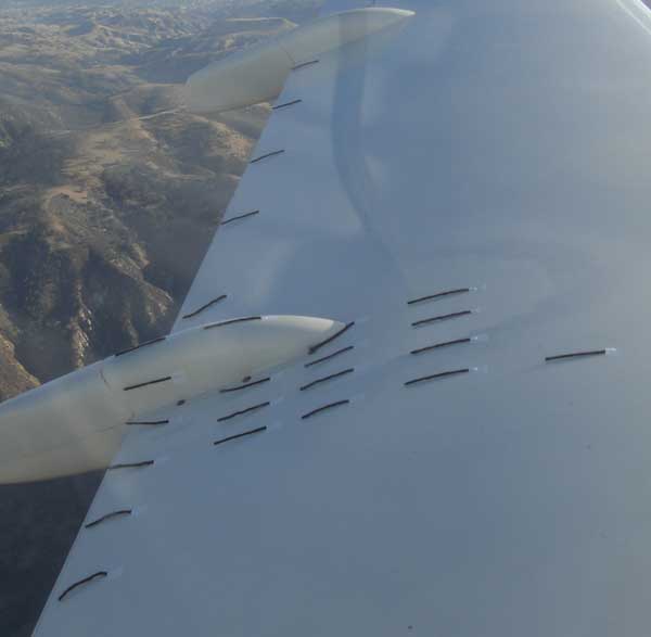
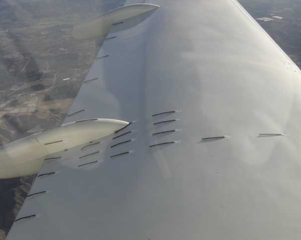
[November 16, 2013]
Finally, after dismantling everything for the umpteenth time, I have the oil and induction air temperature indications working again. I was right on November 5 to think that the oil temp was back to working and the induction air temp wasn't. In the end it was just a question of painstakingly cleaning out a Cannon plug and a Molex connector; all of the wires were intact, and the AN5525-1 resistance temp probes, including a spare, were all good and indicated 100 C when immersed in a bowl of boiling water.
[November 12, 2013]
Yesterday I made a flight to further wring out the Auto-Lean and also to check that the oil temperature indicator was working again. As to the latter, it wasn't; it turns out that what was working, as before, was the induction air temperature - the two use the same indicator, and are selected by a small toggle switch. I need to label the two positions; I keep forgetting which is which. At the moment the oil temp needle jumps to the left end of the dial when oil is selected; I'm not sure whether this means a dead short or an open circuit, but it will be easy to find out.
As far as the Auto-Lean is concerned, I found that peak EGT rose by about 50 deg. F between 2,000 feet, where I initially leaned to 50 LOP (lean of peak), and 12,500 feet, where I leveled out. The power setting was 27/2300 during the entire climb. The result of the rise in peak EGT was that the initial offset of 50 LOP gradually became 100 LOP. I tentatively concluded that I should select 25 LOP after takeoff, let the offset grow to 75, and then re-lean on leveling out.
This is what the Auto-Lean looks like. The black strap over the vernier button keeps it unlocked, so that it can be driven back and forth by a linear actuator that is connected to it with a quick-release fitting. The control head is below and to the right of the flap lever.
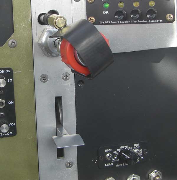
Curious once again about lower power settings, I tried reducing power to 23/1900, about 35%. Here the Auto-Lean did not do so well; it overshot on the lean side, causing the engine to cough and stumble. I disconnected it and leaned manually, eventually settling at a fuel flow of 5.7 gph. This yielded an indicated airspeed of 122 knots, a true speed of 153 knots, and fuel mileage of 27 nmpg; the density altitude was 14,500 ft.
This is remarkable performance for a 4-seat airplane, and I say that without any intent of patting myself on the back. It just seems to have happened. It is particularly unexpected because my performance calculation program predicts that a considerably higher fuel flow - about 6.4 gph - ought to be required to maintain that speed.
A great many assumptions enter into a performance calculation. For example, although the figure of 5.7 gph comes from an Alcor digital fuel flow meter that is most likely accurate, the amount of thrust actually available to overcome drag depends on two unknowns: the specific fuel consumption (sfc) and the propeller efficiency (usually symbolized by the Greek letter eta). At this relatively low indicated airspeed and power setting, furthermore, the fraction of the total drag that is due to lift - the induced drag - is about one sixth, compared with a tenth or so at a more typical 65% power setting; so the total drag is more significantly affected by the factor called e, the "span efficiency factor," which expresses how much worse the complete airplane is than an ideal wing, of the same span and aspect ratio, in isolation. Neither sfc, eta nor e can be known with certainty.
From speeds at higher power settings, where the influence of the induced drag is smaller, I have concluded that the equivalent flat plate area of Melmoth 2 is 2.35 square feet. (This corresponds to a CDp, or parasite drag coefficient, of 0.022.) This value, which by the way is not exceptionally low, is unlikely to change significantly at lower speeds, although my performance calculation program does assume that it will increase slowly with increasing angle of attack. In order to arrive at the observed performance at 35% of power it is necessary to assume a specific fuel consumption of 0.43, a propeller efficiency of 85%, and an e of 0.9. All of these values are right at the limit of plausibility. It seems like a sort of perfect storm of good numbers.
Actually, the rough correction for growth of parasite drag with increasing angle of attack, which is mostly intended to account for the rising pressure drag of the wing, may be wrong. The program makes the CDp 0.0232 at 122 kias; if it is in fact lower than that, then some of the other parameters would not have to be quite so improbably good. But the difference would be small.
So I seem to have lucked out. I recently heard an expression that seemed to me to encapsulate my style of engineering: "putting his spin on a revolving door." In other words, moving, but not going anywhere new. What I have done in designing Melmoth 2 is apply principles that I learned from other people. If the result has turned out unexpectedly well, the credit is theirs, not mine.
Oh, by the way -- I got as far as Santa Barbara, and when I turned back high clouds had painted the afternoon sea with a opalescent sheen.
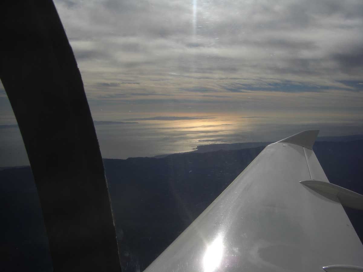
[November 5, 2013]
I finally got the oil temp to settle down by, among other things, swapping probes between it and the induction air temperature. Now, however, the induction air temp is not indicating anything at all. I tried swapping in yet another probe and it still didn't work, so I don't think the thermocouple is the problem. Since the IAT was always unrealistically high with the probe in its present position, I am going to wait until I do the manifold reversal to troubleshoot it.
I finished the permanent installation of the Auto-Lean. In the process, I somehow disconnected a Molex connector in the fuel boost pump circuit; or perhaps it came disconnected as a completely separate misfortune. Anyway, the disconnected connector was behind the panel, thoroughly hidden from view, and I was unaware of it. This morning I was supposed to go up to Paso Robles, but the fuel boost pump wouldn't run, and so the engine wouldn't start. I started taking things apart, and after a while discovered that neither the power nor the ground at the fuel pump had continuity. That should have tipped me off that the problem had to be a connector somewhere -- too unlikely, otherwise, that both legs of a circuit would become disconnected at once -- but instead I was baffled and kept taking more and more things apart until finally I got a clear sight line to the connector. It's always interesting to see how obvious things become once you understand them.
[October 30, 2013]
An email from a Defiant owner who has the same overheating problems as I do when idling his front engine for long periods -- he mentioned Oshkosh, which just happens to be where I, too, have encountered this situation -- got me thinking again about why updraft cowlings might cool an idling engine less well than downdraft ones do. One thought that occurred to me is that when a cowling has two small inlets symmetrically situated beside the spinner, as most downdraft cowlings do, the blades completely occlude the inlets with each passage, leaving air little choice but to be forced into the cowling, whereas the wider single inlet below the spinner that both the Defiant and Melmoth have is only partially occluded, so that air can be squished out on either side of a blade as it goes by.
My correspondent tells me not all Defiants have this problem. If this is true, it does not seem to support my hypothesis; but I'm not sure how scientific a survey we're talking about. I would be curious to know how well various cooling arrangements and inlet designs work during long periods of idling on the ground in hot weather. I assume that any factory product can idle indefinitely on a 100-degree day without exceeding some equilibrium CHT in the middle of the green. (It can't be at the top of the green, because then when you start the takeoff run the engine will overtemp before you get a good flow of air through the cowling.) There aren't a lot of updraft-cooled factory airplanes; maybe some Aero Commanders? Time for a Google search.
[October 15, 2013]
I'm feeling quite pleased with the Auto-Lean. I find that after cleaning up and setting climb power I can just tell it to go to 50 LOP, and I don't need to think about mixture again until I level out. I used to spend 30 seconds or more delicately turning the mixture vernier a bit at a time and waiting for the TIT to hit peak and start to drop; this was time during which I was not keeping as good a lookout for traffic as I might. In addition, it feels more precise than manual leaning does.
Today a photographer, Carla Richmond, who is doing a portrait series of "men and their toys," met me at the airport a little before sunrise - photographers love the "golden hour" when the sun is just on the horizon - and spent a good long time taking about a million pictures of me and the plane and even things like trays full of bolts and clamps, the clutter in my rollaway's drawers, my maintenance log and a dust-covered hand-cream dispenser. When she was done I took her up for a half-hour flight out to the ocean and back. She had never been in a small airplane before, it was a windless and remarkably clear morning, and she thought it all very beautiful and, as she said, "calm." Taking someone up who has never been up that way - under a big transparent canopy, flying low over the hills and the city - refreshes my own sense of the wonder and beauty, and even the calm, of flying.
Nancy and I are going to Boston and New York again tomorrow morning; back in 10 days.
[October 10, 2013]
Flew to Paso Robles to take some measurements from which I hope to calculate the moment of inertia of a Le Rhone radial engine. Knowing the moment of inertia, it will be possible to quantify the gyroscopic moments experienced by an airplane like the Sopwith Camel.
I took off a few minutes before 9 a.m. It was a clear, still day, with a 20-knot flow on my nose but very smooth air over the mountains in spite of that. I climbed to 12,500 feet, set up 27/2200, and let the Auto-Lean gadget find and maintain 50 LOP. It did so, and speed and fuel flow settled down at 174 ktas and 8.1 gph. This was surprising, because it was a little better than expected; I usually say I cruise at 170 ktas and 8.4 gph at that altitude. During the climb I was aware of a sort of rhythmic shudder passing through the airframe every two or three seconds. I assumed it had something to do with the engine, but when I leveled out it disappeared, and so I began to suspect something aerodynamic. I don't know what; I will have to observe it for a while. A quick inspection after I returned to Whiteman revealed a worn piano hinge on the right outboard main gear door; I don't know whether that could cause the vibration I felt, but in any case I need to replace it.
Today the erratic alternator behaved normally; I guess you're not truly erratic until you're erratic only part of the time.
[October 5, 2013]
Sky-Tec fixed the starter for free, even though it was a bit out of warranty, so that's one gold star for them. I don't think I'll bother putting it back on for the time being, however; the weight difference is inconsequential.
I finally got the physical installation of the "Auto-Lean" gadget done, but then it didn't work; it's possible I have the polarity of the wires from the TIT thermocouple reversed. The oil temp needle is still bouncing around and the alternator is still behaving strangely, sometimes showing a 10 amp charge (and 28 volts on the voltmeter), sometimes zero and 25 volts or so. I don't know what to make of this; if it were just the alternator being intermittent, I would expect to see a small discharge on the ammeter (which shows current between the battery and the bus, and normally shows zero in flight once the battery is fully charged) when the voltmeter is showing what appears to be battery rather than alternator voltage; after all, there are various loads, avionics etc, running all the time. Why would it indicate precisely zero current but less than 28 volts? This is shortly after takeoff, when I would expect to see a steady recharge since the battery is slightly depleted from starting and holding at idle. If I run the hydraulic pump, on the other hand, I see a solid 17-amp drain, which suggests that the alternator is not picking up the slack. For the time being I can live with it because the battery seems to stay charged, but sooner or later I have to figure it out. As for the oil temp indicator, that's just a bad connection somewhere; I'll find it sooner or later.
I tufted the left aileron, very sparsely, just to see whether it showed a lot of spanwise flow -- in the inboard direction on the upper surface -- as the ailerons on Melmoth 1 did. (Those were piano-hinged on the lower surface.) During initial climb at 85 kias (takeoff flap) and 95 kias (flap retracted), the aft tuft at the inboard end of the aileron went completely crazy and quickly unwove itself into a bunch of separate strands. The pool of turbulent separated air along upper surface at the the trailing edge is quite evident in this video as well. At 123 kias the tufts looked a bit better behaved:
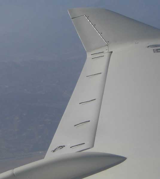
An odd thing is the way the tufts are angled slightly away from the surface at 123 kias; I'm not sure whether that is just due to the expected thickening of the boundary layer or whether it's exaggerated by leakage through the gap. It would be interesting to tuft the undersides, but I have no way to see them.
At 140 kias the tufts cling more closely to the surface:
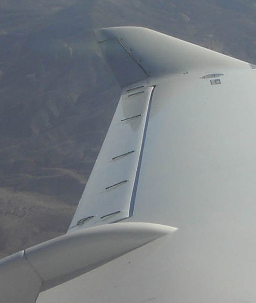
[September 13, 2013]
Yesterday my "lightweight" Sky-Tec starter failed, fortunately at my hangar and not somewhere far away. I installed this thing in late June or early July of 2011, after a previous Sky-Tec design had ruined the starter clutch on my engine to the tune of $800. I forget what I paid for the original Sky-Tec, which I removed in February 2010, but they took $250 more for the new -5 with a clutch that allows the permanent-magnet starter to freewheel when it is not energized, thereby sparing the clutch inside the engine. I probably haven't gotten more than a couple of hundred starts out of the new one, which drew a cool 480 amps on the test bench at Aero Accessories in Van Nuys. Dead short. Nobody I have spoken to has had a kind word to say about any of the lightweight starters; apparently all brands are likewise unreliable. Furthermore, the Sky-Tec, at least, is not field-repairable; I guess you're AOG until they send you a new one (and you send them yet more money). Still, this could be seen as a safety feature; if you can't start, you can't fly.
I will put the old "heavy" starter back on the engine -- the -5 Sky-Tec with the solenoid is not actually that much lighter -- but it will present a new obstruction for the ducting of the reversed intake manifold. I am shopping around for a #6 cyl intake tube for the 360 Continental (I found a #5 and ordered it) so that I don't have to destroy the originals to mock up the new arrangement. I thought I had worked out a very simple path from the existing duct to the throttle body, which is going to be sitting above the vacuum pump, but I realized yesterday that the oil filler neck on my engine is different from the one on the engine installation drawing blueprints I got from Continental 40 years or so ago, and it obstructs the path I had planned. The fat starter will be another problem. Since I plan to connect the log manifold to the throttle body with SCEET hose, little deviations won't really matter, provided that I maintain symmetry. It would be prettier to do the transitions with aluminum tubing, though, and, as in most love affairs, looks are a consideration. Twists and turns that don't bother SCEET can be quite a bit more awkward for aluminum.
This intake-manifold-reversing idea has been floating around for three years now. Nobody could accuse me of plunging rashly ahead.
[August 21, 2013]
Yesterday I got out to the airport -- visiting children and grandchildren have diverted my attention from the Great White Offspring -- and took a bit of a sightseeing flight westward toward Oxnard, then around the end of the Santa Monica Mountains and back along the coast and across the mountains at Malibu Canyon into the west Valley. It's an interesting trajectory, not only because of the variety of city, mountains and sea that it includes, but also because of the always surprising variety of houses built by and for the fabulously wealthy on the ridges and in the foothills. This time I noticed for the first time, at the west end of the range, what appeared to be a couple of huge airplane wings resting on a mountaintop. Descending for a closer look, I found them to be just that; two vast swept wings that had become the roof of a house. When I got home and described this to my son he told me that it is a well-known thing: someone had incorporated a pair of 747 wings into a house in the mountains. Indeed, it turns out that there is a whole Wikipedia article about the place. At any rate, the mountains above Malibu are full of these remarkable houses. In the 1950s, in fact, when these Ozymandias-style palaces were far fewer in number, we used to visit, on foot, the unfinished and highly eccentric house of one Louis (or Lewis) Beach (or Beech) Marvin III, heir to the green stamps (or maybe blue chip stamps) fortune, who briefly dated Gladys, a.k.a. Sissy, the beautiful and clever sister of my erudite friend and schoolmate Tom Houston. In the atrium, open to the elements, a doomed grand piano hung suspended by cables from the roof.
Outbound and returning, I crossed the Van Nuys ILS to check my receiver. After the ILS quit working a couple of weeks ago, I had swapped the nav receivers, so that what was #2 was now driving the #1 OBS/ILS. It worked; at least the needles worked, the flags remaining proudly unmoved. Now each of my almost 40 year old Collins nav receivers has a disability: #2's ILS function is out, and #1 lacks the first digit in the display. Since the first digit is always a 1, this is not a big problem. The oil temperature needle is still wobbly -- I haven't yet gotten around to a really thorough inspection and cleaning of all the connectors and connections -- and the ammeter is displaying an odd behavior: It will display zero for a while, and then five amps for a while, then zero again, then seven amps, and so on. I guess I should know by now that exotic and mysterious electrical gremlins almost always turn out to involve a faulty ground connection somewhere or other.
I turn 70 today; this month the airplane turns 31, if you count from the start of construction. Omnes una manet nox!
[August 6, 2013]
I am neither dead nor ill; just briefly dormant. I was away -- not Oshkosh, but Cape Cod again -- for two weeks, and before that had some writing and other stuff to take care of, so I hadn't been doing much with the plane. I did fly around a bit to see whether cleaning the connectors had corrected the random fluctuations of the oil temperature indication. It was more stable than before, but still not perfectly steady. I need to get some spray contact-cleaning solvent and really wash the oil out of the connectors, particularly the Cannon plug that attaches to the probe itself. In the meantime I became aware that the ILS function of my #1 NAV receiver has quit working. I've begun making the wire harness for the auto-leaning gadget -- see previous entry -- and have mentally reversed the intake manifold many times; now I have but to do it in reality.
[June 14, 2013]
My oil temperature indication -- not the temperature itself, obviously -- began fluctuating rapidly on the flight down from Paso. I cleaned up a bunch of connections, but when I flew to test the vacuum pump -- it appears normal -- the oil temp was still jumping around. I then decided the problem was an apparent short in a miniature switch that selects whether the OT gauge shows oil temperature or induction air temperature. I replaced the switch, but got such unpredictable results -- some good, some bad -- while testing the system on the ground that I gave up fiddling with it until I have a chance to test it again in the air.
As far as the ailerons are concerned, I like them a lot up to 125 kias or so, but at cruising speed (around 140 kias) they're too heavy for me to be able to deflect them fully without extreme effort. I think that after a suitable breather I'll try moving the hinge line back some more.
A guy sent me a gadget to try out, and I'm beginning to install it. It's an electronically controlled mixture servo that seeks a selected EGT, like 50 F lean of peak (my personal favorite) and then holds it. Its usefulness is limited to maintaining a steady temperature; it does not readjust if you climb or descend or change power setting or the OAT has a big change. Still, I'm curious to see how it compares with manual control.
[June 7, 2013]
I got a $100 vacuum pump rebuild kit from Aircraft Spruce and overhauled my vacuum pump yesterday. On the Internet I found various dire warnings against doing this, but I can't see how there can be much harm in it, especially since I fly IFR so seldom. The instructions in the kit were laughable and I had to feel my way, aided by several consultations with a hangar neighbor, Claude Morgan, who knew no more about it than I did but was willing to second my hunches. The rotor was a fraction too thick and bound when the drive end cap was tightened down; I had to sand one or two thousandths off it before it would spin freely. I'll fly it today if there isn't a presidential TFR over the whole LA area. I'll look pretty silly if it fails immediately.
The more I fly the new ailerons the more I like them.
[June 1, 2013]
Today I flew up to Paso Robles for Chuck Wentworth's annual Antique Aero barbeque. On the way up I cruised at 25/2100 at 12,500 feet, 167 ktas with a fuel flow of 7.7 gph. (On a trip up there in February, I went a little slower, 149 ktas at 21/2000, 5.4 gph.) The speed coincides exactly with my computer simulation, which was calibrated to match the measured performance, so despite their larger gaps the new ailerons seem not to have affected the drag to a noticeable extent. The vacuum pump failed at some point; I noticed it when departing from PRB. I think it was the first vacuum pump failure I've had in 50 years of flying. It was quite insidious, and it took me a while to understand what had happened; I'm glad it didn't occur in IMC. Of course, I was in VMC, looking at the DG only intermittently and at the AH not at all. Still, I should have a warning light or tone (or both) for loss of suction.
Behind me on final approach at PRB -- the arrival was like Oshkosh, airplanes everywhere -- was a Lockheed Lodestar, which when it departed in the afternoon made a low pass at speed -- a fantastic looking and sounding airplane with a couple of 1,200-hp P&Ws. I feel a certain affinity for those Lockheeds because they use Fowler flaps like mine, that translate to the trailing edge of the wing before deflecting.
[May 30, 2013]
The new ailerons are now flying. They do reduce the stick forces, but at cruise speed (usually around 145 kias) the forces are still a little higher than I would like. Very roughly, I would guess that the stick force per unit of aileron deflection is now about half what it was before. Because of the design of the hinge hardware, I still have the option of shifting the hinge line farther aft by small increments. At the moment I feel all aileroned out, but I may start fiddling with the hinge location again in the future. It is currently 1.2 inches (at the root) aft of its previous position.
The testing procedure consisted of two phases. The first was to establish that there was no reversal or overbalance. I tested this by putting the airplane into a 45-degree bank in one direction and then applying a full stick deflection in the other. You want the stick force to be at least constant, or to increase more or less smoothly, with increasing aileron deflection. If the resistance diminished as the aileron deflection increased, it would be a sign that the ailerons were overbalanced, that is, the hinge line was too far aft. The worst case would be that the ailerons would pull away from center, a condition known as "snatch." You do this test at a fairly low speed so that there is no danger of the ailerons going to full deflection and your being unable to re-center them. A related issue is aileron reversal, in which the deflected aileron, acting behind the torsional axis of the wing, twists the wing in such a way that up aileron makes the lift increase rather than decrease. My wings are quite stiff, being thick -- 13% at the tip and 18% at the root -- and skinned with carbon fiber, and at the speeds I fly aileron reversal is not likely.
The other thing that needs to be checked is susceptibility to flutter. Again, low (ie under 200 kias) speeds and thick, stiff wings make flutter comparatively unlikely, but since it depends on an accidental coincidence of resonant frequencies you can't be sure without either ground vibration testing or in-flight testing by "pulsing" the controls. The former is very expensive, the latter a bit nervous-making, but free. John Thorp called it "tickling the dragon's tail." Beginning at a low speed and working upward by small increments, you slap the stick sideways hard enough to give the ailerons a visible jolt. You want them to return instantly to trail without oscillating; this is called "dead beat" behavior. I have so far pulsed the ailerons at up to 150 kias and their response is dead beat; as the testing progresses I will go up to 190 kias, which is the speed to which the rest of the controls, and the original ailerons, had been cleared by Mike Melvill in 2002. The faster you go the closer you are to the speed of onset of flutter -- which could be 300 knots or 191, no way to know -- and it's customary to dive past the target speed and pulse the surfaces while decelerating through it, just in case something starts to shake.
Prior to test-flying the ailerons I ran some computer analyses on them, using the PSW panel code. I made simplified models of the new ailerons and the original ones and computed the pressure distribution on their surfaces. I then integrated the pressures on the aileron surfaces only and obtained a moment about the hinge location. According to the computer, the hinge moments of the new ailerons were about 30% of those of the old ones. More important, they were of the same sign at maximum deflection; in other words, the computer did not think that snatch would occur.
Here is what the pressure distribution on the wing with an upward-deflected aileron looks like. The redder colors represent low pressures, green neutral, and blue high. Note the bulge on the lower surface, which is the leading edge of the aileron emerging below the airfoil contour because the hinge line is so far aft -- it's on the chord line, about at the station of the yellow band aft of the fuchsia bulge. It's noteworthy that although the angle of attack of the wing was zero for this analysis, the upward deflection of the aileron causes the pressure distribution over the entire airfoil, normally low pressure on top and high on the bottom, to be reversed. In other words, the increment or decrement of lift caused by a deflected trailing-edge flap is not confined to the flap itself; it is spread over the entire surface.
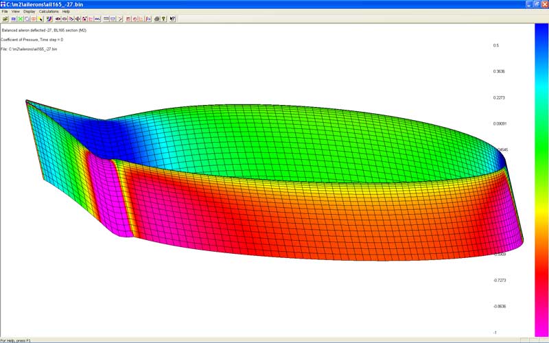
One final thing that was gratifying -- the two ailerons were sufficiently similar to one another that there was no apparent need for a trim tab.
[May 6, 2013]
Final weights on the ailerons, with 100% static balance, are 1,363 g (3 lb) and 1,284 g (2 lb 13.3 oz). Contouring, paint and counterbalance added nearly 50% to their weight. Each is about 1 kg (2.2 lb) lighter than the original ailerons.
[April 28, 2013]
Nancy and I returned on Wednesday night from a three-week trip. I spent Thursday answering letters and recovering from a cold I caught while away, and on Friday went to the airport. I intended to fly, but I found that my head was still so congested that my ears would feel full just going up and down the hills of Echo Park, so instead I did a little more work on the ailerons. I tested their stiffness by supporting them on their hinge pins, placing a 21-pound cinderblock at mid span, and measuring the deflection, which was about .12 in. for a 60-inch span. The purpose of this test was merely to be able to compare their stiffness with that of the original ailerons in order to see whether they are likely to create any new susceptibilities to flutter. I also measured the mass required to balance them, and was mildly surprised to find one of them requiring nearly twice as much as the other. The difference reflects different amounts and distributions of filler on their surfaces, magnified by the filler being farther from the hinge line than the counterweight is. I ordered 12 feet of 5/16 x .035" SS tubing from McMaster-Carr to use as counterweight material; it should arrive on Tuesday.
[March 29, 2013]
I notice, looking back over the past few weeks of entries, that 1) I have been progressing very slowly and 2) I have been repeating myself quite a lot. The repetitions are due in part to the sporadic nature of these reports, which gives me time to forget what I said in previous ones, and in part to the fact that whatever can be said about one aileron is likely to be equally true of the other. Besides, I'm getting old. A new rudder would perhaps involve less redundancy. As far as the slowness is concerned, it is due mostly to competing demands on my time. If I had my druthers I would spend more time working on the plane than I do; it is sad that my father thoughtlessly neglected to amass vast wealth.
I see that some time ago I said that I would test-fly the ailerons before painting them. Obviously, I didn't. In retrospect I'm not sure why I thought that would be a good idea; the only thing about them that can be changed is the position of the hinge line, and that can be done just as well after painting as before.
I had an instructive experience a few days ago. My oil filter is mounted upside-down, so that it drains into the engine after shut-down and therefore never spills any oil when it is changed. I had changed the oil and filter a few days earlier, and had not removed the top cowling to do so, since it is not difficult to get at the filter through the left side cowl panel. Last Thursday was the first time I intended to fly after the oil change. I started the engine and taxied a few hundred feet, but I kept hearing an odd sound, a sort of sssht...sssht. Then I noticed that my oil pressure was about 10 psi, and I immediately shut down the engine. I looked back to see a trail of oil where I had been and a hangar neighbor following me on foot; getting out, I found oil pouring out of the cowling. Together we pushed the airplane back to my hangar; he was kind enough to get a bag of kitty litter from the gas pit and spread it on the pool of oil I'd left on the taxiway. I wiped the worst of the oil off the cowling and fuselage and sprayed everything with detergent before going home. It was apparent that the oil leak was coming from the oil filter, but I didn't know why. The next day I took off the filter and found that when I removed the old filter its gasket had fallen off and remained resting on the mounting pad, somewhat off-center. Because I was looking into the cowling from the side, I had not seen it. When I put on the new filter it tightened down on top of the old gasket. It looked and felt normal, but actually was not sealed at all.
I had to add eight quarts to bring the oil back to its normal level -- which is eight quarts. No harm seems to have been done -- the next time I flew all temperatures, pressures and sounds were normal -- but henceforth I will be more attentive to even routine jobs like unscrewing an oil filter. And if you had asked me whether I always check oil pressure after start-up, I would have said yes; but obviously I didn't.
[March 28, 2013]
I'm finally painting the ailerons. I should just have time to attach the hinge hardware at the start of next week and perhaps balance them -- probably not the latter -- before leaving on a three-week trip to the east coast. The current plan, when I get back, is to take them out to Mojave, install them there, and make the first test flight from the 10,000-foot runway. I doubt that they will be overbalanced; in fact, my main concern is that after all this work there will be little or no difference in their hinge moments.
Although the aileron looks oddly beige in the photo below, it isn't; it's "ivory", the same color as the rest of the airplane. In fact, if anything it's lighter. I'm painting it, as the rest of the plane was painted, with a brush, but it's not coming out as smooth as the rest of the airplane. I've lost my touch.
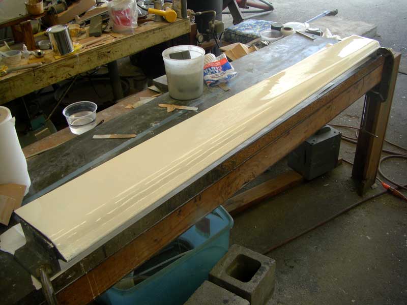
[March 16, 2013]
As I did on the left side, I removed the right aileron in order to 1) make new hinges and 2) put the old hinges and aileron back into place. This took a several hours of cutting and fitting. Before replacing the old aileron, I temporarily put the new one into place, adjusted the hinges so that the lower surface was flush with the wing, and laid down a strip of filler over about half the span of the upper side where the wing surface was slightly higher than that of the aileron. That strip of filler, which is just a couple of inches wide and feathers into the aileron surface at its rear edge, will serve as a guide for contouring the upper surface. (The leading edge of the filler strip is rough because I trowelled my excess filler on there; it's the smooth upper surface that will be the guide.)
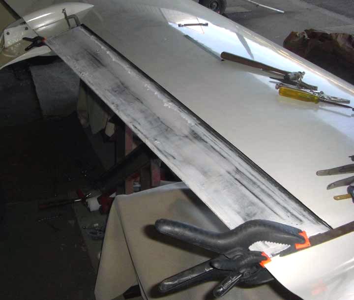
[March 7, 2013]
In the past couple of weeks I have found time to laminate the second aileron and complete the contouring of the first. It's incredible how long this has taken me; small wonder the entire airplane took 20 years. The last step in contouring was to spray the aileron with several coats of a dark gray primer and wet-sand it with 600. The result is a very pleasing surface, reminiscent of the Santa Clara black pottery one sees in Santa Fe; unfortunately this will have to be replaced with boring fake-looking glossy white paint in which a few bugs and bits of airborne grit are bound to become entombed. It was interesting, by the way, and surprising, to find that the weights of the two ailerons, in their uncontoured state, were within a few grams of each other: about 815 grams, or 28 ounces, each. Their area is 2.7 sq. ft. Unfortunately, countouring, balance weight and attachment hardware will increase that weight by 50%.
Part of contouring each aileron is to mount it in the wing and ensure surface continuity. To do this on the right aileron I have first to revise the hinges on that wing; so I still have a way to go. On the left side I contoured the underside first, adjusted the hinges to position it correctly, and then laid down a band of filler on the top surface and squeegee'd it to the proper height with a thin aluminum strip bridging the wing and the aileron. After it cured I used that band as a guide for contouring the rest of the upper surface. The layer of filler is mostly very thin; you can see the underlying black skin through it.
I have been busy in the past few weeks designing a set of new wheel pants and gear leg fairings for an old Stinson. The result looks very close to optimal on the computer, but you never know how these things are going to behave in real life. The existing pants showed horrible flow separation between the leg and the inboard side of the pant facing it. Whoever designed them seems to have had no idea of interference drag.
[February 16, 2013]
Contouring -- filling and smoothing the surface before painting -- notoriously requires hundreds of hours of tedious and messy work on composite airplanes whose skins are not made in female molds. The curse of it is that the closer you come to perfection the more glaring tiny imperfections appear, and so you feel compelled to erase increasingly inconsequential blemishes. Almost all of the contouring on my airplane was done by a professional, Roy Bailets, and I have never developed much skill in that department. So I can have major stumbles, as I did when I so grievously undercatalyzed a coat of polyester primer on one side of the left aileron that I had no choice but to scrape it off. Twenty hours after application it still had the consistency of clay. I have since learned that the recommended ratio of primer to catalyst is 64:1. I had misguidedly used something like a tenth of the proper amount. Why did I not read the directions on the can? I did. They said something like, "For mixing instructions, see product data sheet" -- a data sheet that I did not have.
[February 3, 2013]
On Monday, the day I was intending to test the left aileron on the airplane, I received an email from a reader of this site, Harry Manvel, warning me to approach asymmetrical ailerons with caution. He knew a builder, he said, who had flown with two different ailerons, and had had to hold full lateral stick deflection until he could get back on the ground. In that case, the chords of the ailerons had been quite different, Manvel said, and so it "might be apples and oranges." The chord of my new ailerons is the same as that of the old ones, but his warning got me thinking, and I realized that because the hinge moments of the two ailerons would presumably be different, and since ailerons naturally tend to float upward, the old aileron would float upward, overpowering the new one and pushing it downward, and I would have to hold left stick continually. This could be quite unpleasant, since the roll forces are high and the stick is very short. Left stick, furthermore, is the more difficult to hold. Even if the situation were not dangerous, it would camouflage whatever impressions I hoped to get of the feel of the new aileron, and would render the whole experiment pointless. So I didn't do it.
[February 2, 2013]
The weight of the left aileron is now up to 2.5 pounds. That includes the attachment hardware and a 100-gram, or about 3.5-ounce, balance weight in the nose. The rest is filler. The balance weight consists of a 20-inch length of 5/16" stainless steel tubing, slipped into the 3/8" tube that is built into the nose of the aileron, and held in place spanwise by wooden dowels inserted from either end. Cotter keys retain the dowels. Because the hinge line of the the original ailerons is relatively farther forward, they required considerably more balance weight and weigh about 5 pounds each.
I was surprised, when I got the dowels at Home Depot, to see that they were made in China. How can it be that a round piece of quite ordinary wood, manufactured by an entirely automatic process, can be more cheaply created in China and shipped to the US than made here?
If other obligations do not prevent me, I will install the left aileron and fly it early next week to see whether there is any indication of hinge moment reversal -- or, for that matter, of hinge moment reduction. Of course, with one of the original ailerons and one new one, it will not be easy to tell what is what; but I hope to get some useful impressions.
[January 22, 2013]
After several days of filing and fitting, I finished the new aileron hinges for the left wing. The aileron somehow turned out to be the right length; it did not require any fancy shims or joggles to slide snugly into place between the hinges. The trickier hinge was the outboard. The original hinge consists of a flanged bellcrank bearing set in a 3/4-inch hole in a fiberglass plate. The new hinge is a 3/4" O.D. spherical bearing, and its center is 0.825 inch farther aft. The whole assembly fits within the contour of the wing, which is about 1.5 inch deep at this point. The problem was how to integrate the new hinge with the existing plate without making it impossible to re-install the existing bearing, since I am not yet ready to permanently install the new aileron. It was touch-and-go for a while, but everything worked out nicely in the end.
I have begun contouring the left aileron; here it is mounted to a work table and slathered with a mixture of glass microballoons and epoxy.
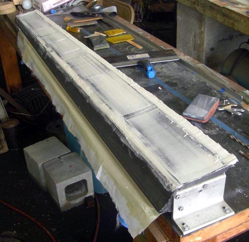
The procedure is to put on too much and then sand it away. The bare aileron weighed 850 grams, or about 1 lb 14 oz; I am curious to see how much the finish adds. Notwithstanding my earlier resolution to leave the underside uncontoured, I am doing it because the trough where the lower skin joins the upper at the trailing edge is on the underside, and it has to be filled anyway. Filling the weave over the rest of the surface adds very little weight, and reduces the risk that I will sand though the skin at the edge of the trough. I know of one instance in which the builder of a composite homebuilt actually got killed by overly zealous sanding.
[January 11, 2013]
The inboard end of the aileron looks like this.
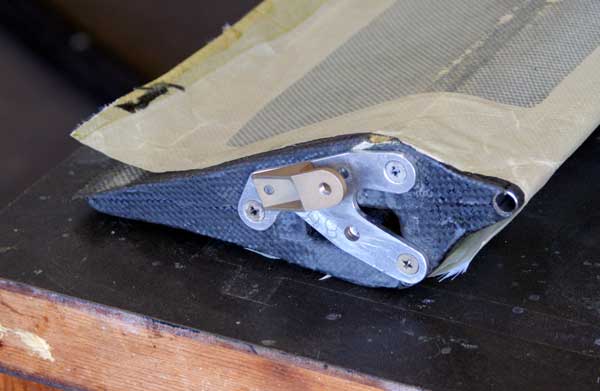
The lower hole, with the nutplate threads just visible, is the hinge point; the actuating pushrod will be pinned through the upper holes. Hinge and pushrod attachment are an inch apart; the chord here is about eight inches. The rectangular well in the end rib is to provide clearance for the nutplate in case it needs to be moved to adjust the aerodynamic balance. The hinge point is currently at 25% of the nominal chord -- by "nominal" I mean not counting the extension for the counterweight.
[January 7, 2013]
Despite the holidays and the diversion of our visiting children and grandchildren. the left aileron is nearly done; I just need to prime the aluminum hardware at either end and fill the notch at the trailing edge. It currently weighs just under two pounds, but that will go up a bit with paint and the nose counterweight.
I was in doubt as to whether to fill and smooth the surface before painting it. A nicely finished surface would look nicer, of course, but otherwise serve no purpose. In principle, I should not care if people looking at it say to themselves, "Wow, what a mess!" But Mike Melvill said that he grew heartily tired of explaining the unsmoothed control surfaces of Rutan's original VarEze to curious onlookers, and recommended filling and contouring as a preventive measure. My compromise solution will probably be to contour only the upper surfaces; that way I will have to explain myself only to little people. In any case, I will not paint it before test flying it.
Here is the detail at the tip, with the corresponding parts from the other tip beside it. The chord of the aileron here is five inches.
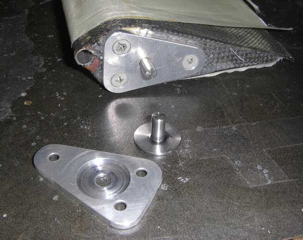
The requirement was to provide a 1/4" steel pin for the hinge, and distribute the forces from it into the phenolic end rib and from there into the carbon skin, while preserving the option of moving the pin fore or aft to adjust the stick forces. The solution I chose is a 1/8" aluminum plate secured to the aileron end with three 10-32 countersunk screws, and a flanged stainless-steel pin that nests in a recess in the plate. The flange is very slightly thicker than the well is deep, so that it is clamped in place against the aileron. The load to be carried is on the order of 80 pounds.
The tube in the nose of the aileron is part of the counterweight. It is 3/8 x .028 SS, and runs the full length. I plan to add additional weight, up to about 105% static balance, by sliding a 5/16-inch wooden dowel into the SS tube with lead pellets epoxied into holes drilled in the dowel.
I still have to modify the hinge brackets on the wings, both to allow adjusting the hinge line if necessary and to preserve the option of going back to the original ailerons if for some reason I choose to.
[December 12, 2012]
This morning I laid up the lower-surface skin on the left aileron and vacuum-bagged it. The bag is simply a piece of 4-mil plastic sheet (the kind that is sold in 10x25 foot rolls in hardware stores) folded over and sealed along the edges with some very sticky mastic called bagging tape; I suspect this stuff must have some more mundane primary purpose in the building trades, like bedding window panes, since it is fairly cheap. The single-ply skin of 10-mil bidirectional carbon cloth is covered with a thin ply of dacron, which peels off later (hence the name "peel ply") and leaves a clean surface ready for subsequent bonding or finishing. Then comes an absorbent layer to wick up excess epoxy; I used a cut-up T shirt. A couple of straight extrusions are taped to the underside of the foam core, and a piece of 1/2-inch square steel tubing is laid atop the trailing edge, to keep everything straight. I use about half an atmosphere of vacuum; that's not very critical in this case, since I am not forcing a large amount of epoxy out of the carbon skin. The weather is cool -- around 60, with rain coming -- and it will take a couple of days for the layup to cure thoroughly, but it will be sufficiently cured tomorrow to remove it from the bag. Time permitting, I may be able to do the other side on Friday. In the picture below, the light-brown stuff is the epoxy seeping through the T-shirt, most of it in the vicinity of the spar cap.
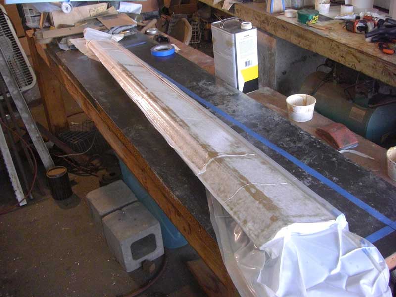
[December 6, 2012]
I bonded the stainless tube into place for the left aileron. I was uncertain whether to then do the same for the right or to complete the left first; I will take the latter course, so as to avoid any irrecoverable mess-ups. I tried in vain to get the two 30-inch segments of trim (which I intended to use as supports while bagging the skin) to line up properly. The idea was to bag the trim blocks -- the portions of the foam blocks cut away when hot-wiring out the aileron cores -- down to the flat table, then to lay the aileron core on them and bag the skin onto one side of it; but as soon as I pulled a vacuum on the trim blocks they would turn out to be slightly misaligned, in spite of my repeatedly shimming them with layers of .003 plastic sheet. Plan B is to secure a couple of straight extrusions to the backside of the core with masking tape, and then to use a free bag for the lamination. The important thing is just for the ailerons to be more or less straight and particularly for the trailing edge to be straight, since it is the place where a kink or wave would be most obvious to the eye. Aerodynamically, perfect straightness will not make much of a difference.
I flew to San Luis Obispo yesterday wth Mike and Sally Melvill to see Ray Henning, who was down from Seattle with his friend Yvonne to visit wineries and the scenes of his reckless youth. The day was perfectly clear and in the late-afternoon light, as we returned to Tehachapi, the mountains and valleys of the coastal range were very beautiful.
It was dusk as I flew back to Whiteman, and I had the flashers and nav lights on. At a certain point I noticed that the ammeter was indicating a 10-amp charge -- it ought to show zero, once the battery is fully charged, which it normally is within a few minutes of takeoff -- and the voltmeter was indicating 26 volts rather than the expected 28. After a minute or so of this the ammeter suddenly jumped back to normal; and after a few more minutes this behavior repeated itself. I hate electrical gremlins; I never understand them.
After the 100-mile clarity of the rest of the trip, the LA basin was filled with a thick haze; Whiteman was VFR, but, although it was still twilight and there was plenty of ambient light, I could see only the two VASI lights until I got within a mile and a half of the runway. I don't know how newcomers manage to find an airport on days like this.
[November 30, 2012]
Some progress, despite the holidays, which tend to bring everything to a halt. I laminated the end ribs into place with two plies of carbon. The bidirectional carbon cloth I have turns out to be .010 thick, not .006 as I believed, so I will use just one ply for the skins. The end ribs get the additional ply because they support all the concentrated loads. Mike Melvill machined some small parts for the inboard hinge and pushrod attachment and the outboard hinge pin. Each aileron will be held in place by a single bolt; a cantilever pin projecting from the end rib will slide into a spherical bearing at the outboard end. The next step is to bond a 3/8" stainless steel tube into place in the leading edge; the mass-balancing material will go into it.
[November 16, 2012]
I was wrong to think that I will be able to skin two ailerons at once. I overlooked the fact that the two outboard cores were cut from the same blank, overlapping one another. I suppose, however, that something is to be said for learning from the mistakes I will inevitably make on the first aileron, and avoiding them on the second. Not to say that I will avoid making new mistakes on the second.
The first blunder I uncovered was that I used a blank 31 inches long for the outboard cores, believing it was 30 inches long; hence there is a small, probably undetectable error in taper, and I had to cut the end ribs off those cores, trim the cores to the proper length, and reattach the ribs. I am now adjusting the heights and positions of the trim pieces that will support the cores during skinning. One lesson that I learned too late is that it was a false economy to cut the two end cores out of a single blank; I should have used a different blank for each core, and set the templates in such a way that they ended up properly aligned on the table without a lot of trimming and shimming. Here, at any rate, is the core for the left aileron, temporarily laid out on the workbench. The groove for the spar cap is visible, as is the pocket in the inboard end rib that allows the nutplate for the hinge bolt to be adjusted fore and aft.
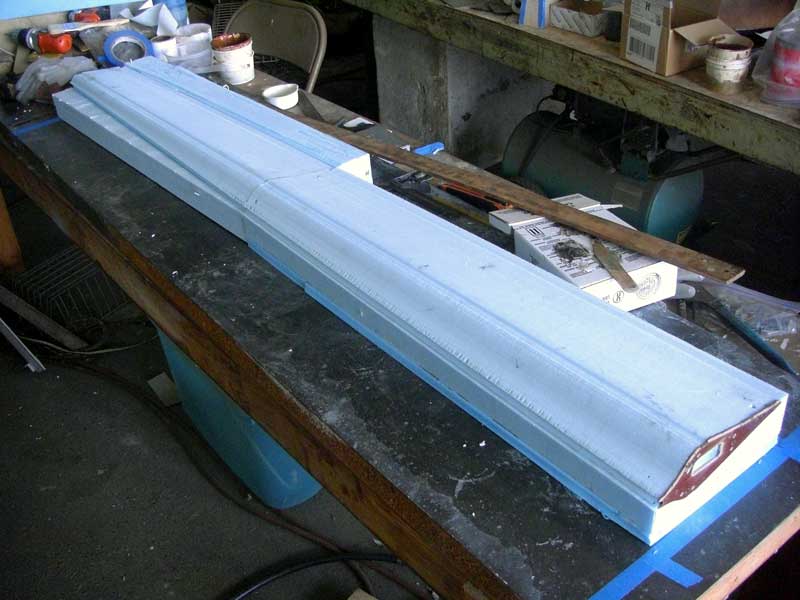
[November 10, 2012]
It's difficult to predict the hinge moments of aerodynamically balanced control surfaces, and so I designed the new ailerons to allow the hinge line to be shifted over a pretty wide range. Three #10 nutplates on each of the 1/16" phenolic ribs embedded in the inboard and outboard ends of the ailerons -- these are the same phenolic patterns as were used for hot-wiring the cores -- allow the chordwise position of the hinge hardware to be adjusted. Of course, the hinge points on the wings have to be adjusted too. Maybe, however, I'll get lucky and the hinge moments will be acceptable the first time around, using what seems, from a half-century-old NACA report, to be a good default position.
So far I have only bonded the phenolic ribs to the cores. The next step is to vacuum-bag two plies of carbon cloth over these end ribs, extending an inch or so over the core. After that, I will align the two 30-inch core segments of each aileron with each other, supported by the foam blocks out of which they were cut, and bond in place the 3/8" stainless steel tube that runs as a counterweight along the projecting leadng edge (see here). After that, one side (the bottom) is skinned, the whole thing is flipped and the other side skinned, and finally a closing tape is added along the leading edge. The unidirectional carbon spar caps, which are there to prevent the ailerons from bowing excessively under air loads (since the hinges are at the outer ends rather than at intermediate locations along the span), will be sandwiched between the two plies of the skin.
This is quite a lot of operations, but I think that although the skins can go on only one side at a time, it will at least be possible to do both ailerons at once.
[November 8, 2012]
Melvill and I flew to Paso Robles to check out some test equipment in one of Javier Arango's Sopwith Camels. This time Mike remembered to bring his iPad and Stratus ADS-B receiver. Although my initial impression was mainly of the number of thumbprints an iPad accumulates and of their remarkable conspicuousness under a bubble canopy, I couldn't help being impressed by the torrent of information the thing supplies. Situational awareness will become a thing of the past, I fear. I hate to admit how much time we spent staring at the iPad rather than looking outside the airplane.
[October 31, 2012]
Today is the tenth anniversary of Melmoth 2's first flight.
Yesterday Mike Melvill and I flew up to Stockton to have lunch with Dick Eklund, an old friend of mine and protege of John Thorp's who lives in what used to be Thorp's house, built in 1862 by Thorp's grandfather. That gent came to California with the gold rush, but rather than prospect he opened a grocery store in what is now Lockeford. Dick manages the support of T-18s, and has been repairing his own T-18 after an accident. It's nearly ready to fly again. Mike's EZ was having an oil change, and so I picked him up at Tehachapi. The round trip was about 620 sm, the time about 3.5 hours, and the fuel burn around 32 gallons. We cruised at 11,500 and 12,500, at the usual 140 kias and 8.5 gph. There were no clouds and very little wind; on the way up our GPS groundspeed, 174 knots, was identical to our true airspeed, and on the way back down we may have had two or three knots of headwind.
Mike had intended to bring his iPad, but forgot it, to his great regret because he was enthusiastic about showing me what a great convenience it is for flying. It happens that a friend of ours, believing that she had lost her iPad, bought a new one, only to have the old one returned. She lent it to us, and I am going to try it, once I find out what accessories and subscriptions I need. Mike commented on getting into my airplane on the "classic" instrument panel; he suggested -- I believe facetiously, but I'm not certain -- that it might be a good idea to just velcro an iPad up over it.
[October 24, 2012]
In ten years I have had six biennial static/transponder checks, and of those two have involved me in expense and wasted time because of false results that turned out to be due to problems with the test equipment. This time, at least, the technician stuck around to troubleshoot the problem, and offered to pay the cost of my having unnecessarily shipped the encoder back to the manufacturer after his previous visit (I declined). He also helped me find a static leak, where I had modified the plumbing last year because of a problem with water getting into it. Anyway, now everything is fine again.
Tomorrow Russ Hardwick and I are hotwiring the cores for the new ailerons. The hotwire is a 43-inch-long piece of .032 stainless steel safety wire stretched taut and electrically heated to the point that it melts or vaporizes its way through plastic foam. Two people guide the wire along templates secured to the ends of the foam blank, using correspondingly spaced and numbered index marks to keep in step with one another. If all goes well, the result is a smooth foam core of exactly the right shape and size. To prevent the wire sagging because of the drag of the foam, we are going to do two 30-inch cores instead of one 60-inch one. The portion of the foam block that lies outside the core will later serve as a jig to support it during laminating.
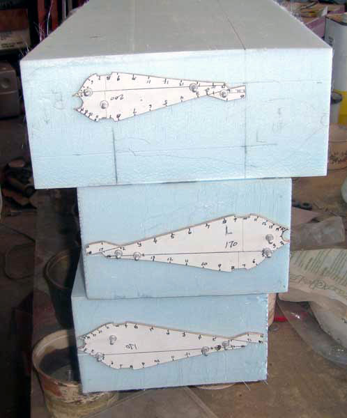
[October 14, 2012]
Someone asked whether the panel lights should be red to preserve night vision.
I learned to fly 50 years ago. At that time panel lights were usually red and the instrument panel itself was black. At some point, I forget when, panels began to be painted gray and instrument lights turned white. I don't know why this change occurred, though I'm sure it is well documented in the annals of the FAA Aeromedical people at Oklahoma City. Perhaps it had to do with middle-aged pilots using white flashlights to read increasingly crowded charts. Perhaps it was an early signal of the gradual decrease in sensory connection between pilots and the world outside the cockpit, epitomized today by game-like electronic displays for navigation and terrain avoidance. My habit, when I was regularly flying at night, was to turn the panel lights as low as possible and to allow my eyes to achieve the greatest possible degree of dark accommodation. It was pleasing to be able to discern through Melmoth's transparent canopy the Milky Way, the swarms of faint stars, and the outlines of mountains against the faint skyglow of a western night. While crossing the Pacific, in fact, I turned off all the interior and exterior lights for a while in order better to appreciate the spelean blackness that surrounded us.
From an old man's reluctance to relinquish habits formed when I was first a pilot, I have painted the panel of Melmoth 2 (or at least the parts of it that I have bothered to paint at all) black, and I suppose that if I were to resume night flying, which is unlikely, I might find the five white LEDs that currently constitute my entire interior lighting unacceptably bright. It would not be very difficult to replace them with red ones, and/or to add a dimmer.
[October 11, 2012]
While waiting for my encoder to return from the factory, I wired and temporarily installed some panel lights. I had bought five medium-intensity LEDs and mounted them in parallel on a piece of thin fiberglass laminate. (My friend Russ Hardwick, who knows something about electricity, says I should have put them in series; to my objection that that way the failure of one would cause all to fail he replied that LEDs never fail. I guess I could have provided an equally forceful argument: I never fly at night.) The choice of five was sheer guesswork, but turns out to be a pretty good first cut, if my impression of their brightness from throwing a rug over the canopy and sitting inside is any indication. The assembly is currently just snapped into place in the overhead and held by friction. The panel lights share a switch and breaker with the nav lights; at the moment there is no provision for dimming.
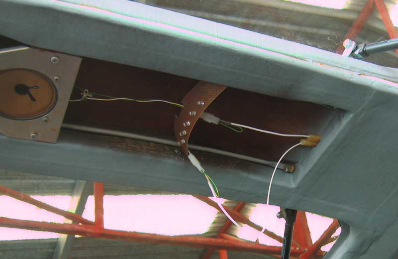
[October 9, 2012]
I converted the paper templates into computer files of coordinate lists in airfoil section format, and thus was able to ensure that the middle one was precisely intermediate between the ends and that all three matched the corresponding wing sections. Based on Part 23 control surface loads, the limit load on each aileron is 154 pounds, which produces a moment of 1150 in-lbs about 25 inches from the inboard end. The section depth at that point is about two inches. By good luck I happened to have a slab of the unidirectional carbon fiber laminate that I made for my wing spar caps back in the 1980s (never throw anything away!). It is .080 thick, and strips about 3/8" wide along the top and bottom high points will provide the requisite bending strength and stiffness. A single ply of bidirectional carbon cloth would be sufficient for torsional loads, but I think I will use two plies for the sake of a more durable surface. The last few days I have been busy with my biennial pilot-static-transponder certification and with wiring panel lights, however, and I have not made any practical progress on the ailerons.
[September 28, 2012]
To the three approaches to reducing aileron hinge moments listed below, a correspondent added yet another: pneumatic boosting. He suggested using the pressure difference between upper and lower wing surfaces, but I think ram pressure would work better. The pressure would be valved to bellows that would push the ailerons one way or the other, depending on stick position. Denny Polen used that method in his Polen Special, a 300-mph Midget Mustang. But I think it's a bit too complicated for me.
After fiddling around on the computer for hours, I finally reverted to the old paper cutout method of designing control-surface profiles, with this result:
The length of the longest section is 8 inches. The profiles represent the inboard and outboard ends of the aileron and a section halfway between them; the foam core would be hot-wired in two 30-inch-long segments, because it's difficult to hot-wire small radii over a 60-inch span. The nose contours are designed to provide 1/8" clearance from the existing cove lips at full deflection. The projection on the leading edge is provision for a counterweight, basically a piece of 3/8" diameter tubing of aluminum or steel that runs the entire length of the aileron.
[September 27, 2012]
Several readers joined the discussion of aileron balancing. One suggested spade balances, which competition aerobatic airplanes often have. These are flat plates, normally aligned with the airstream, mounted on arms projecting downward and forward from the ailerons. They are powerful and convenient, but too draggy to use on what is supposed to be a clean airplane. Another asked whether gearing couldn't be used to reduce the stick forces. The answer to that question, which is not intuitively obvious, is no: a series of bellcranks between the stick and the aileron can slightly modify the distribution of effort vs deflection, but the total amount of work that has to be done remains the same. In other words, only the stick length and swing, and the aileron hinge moment, matter; all the gearing between them cancels out (except for a little additional friction).
A question was raised about the need for thickening the aileron on the lower surface as well as the upper, since flow has a natural tendency to remain attached to the lower surface. The point is well taken, especially in view of the fact that with the wing developing lift there is going to be some leakage through the aileron gap from bottom to top. I would think it would mostly involve boundary-layer air, and would enhance the likelihood that a more energetic flow would reattach to the lower surface of the aileron. I don't think, however, that any harm would come from thickening both surfaces of the ailerons, and the balancing effect of flow over the portion of the aileron ahead of the hinge might be enhanced.
I realized last night that the design as shown below has a potentially dangerous characteristic. I defined the hinge location in such a way that the nose of the aileron, which is a circular arc, would touch the cove lip at its extreme upward deflection of 25 degrees. The problem with this lack of clearance is that under load the wing and aileron may bend differently, and the lip could bite into the aileron and trap it. Something of that sort happened to a factory Cirrus during flight testing. Because it occurred at low altitude, the plane, which wouldn't stop rolling, crashed before the pilot could bail out. I have to either shorten the aileron chord and move the hinge backward a little more, or else take a divot out of the leading edge to provide clearance. The divot is probably the better choice. It would normally be hidden within the cove, and so it would not add any ugliness (always a major consideration).
[September 24, 2012]
One of my few persistent dissatisfactions with Melmoth 2 has been with the aileron hinge moments -- that is, with the stick forces in roll. At 140 kias, the ailerons don't move more than two or three degrees before the stick force becomes uncomfortably high. As a result, I have never rolled this airplane. I used to roll Melmoth 1 all the time -- probably to the dismay of my passengers. Melmoth 2 would be more fun to fly if it had lighter roll forces, and I have thought a great deal about how to bring that about.
Various approaches are possible; they fall into three categories. One is to slice off a portion of the trailing edge of each aileron, hinge it, and link it with a pushrod to the wing in such a way that deflecting the aileron upward causes the tab to rotate downward; this is properly called a "lagging balance tab," though many people would call it a "servo tab." A second approach would be to recontour the ailerons, making them flat-sided rather than cusped and providing them with a beveled trailing edge; this approach was used on Mooneys, which were notorious for their stiff ailerons. A third approach would be to replace the present ailerons with aerodynamically balanced ones.
I'm against beveled ailerons because they're so ugly. Balance tabs add weight at the trailing edge, where you least want it, and reduce the effectiveness of the ailerons. Aerodynamically balanced ailerons imply larger gaps and some additional drag, and their behavior is very difficult to predict. So I have remained in a quandary, and done nothing, lo these many years.
Lately, however, I overhauled the control-surface-design portion of my lofting program, and now I have Hoerner and various wartime reports on aileron hinge moments spread out on my desk and am teetering on the brink of making myself a new set of ailerons. Pretty much for aesthetic reasons, I am inclining toward the aerodynamically balanced variety. The most generally useful source of data on these is NACA Advance Confidential Report No. L4E13 from May, 1944, ANALYSIS OF AVAILABLE DATA ON CONTROL SURFACES HAVING PLAIN-OVERHANG AND FRISE BALANCES, by the alliterative duo of Paul Purser and Thomas Toll. The importance of balanced controls increased during the war as fighter speeds rose and bombers grew larger but boosted controls had not yet become the norm. Their design is tricky; they are sensitive to hinge position and nose shape, as well as angle of attack. It seems, however, that the most reliable first cut is to design the section with a circular-arc leading edge, as if it were unbalanced (this is the current design), but then to shift the hinge line aft to about the quarter-chord point of the aileron. Since there is some risk of overbalance with this procedure, I am considering a design in which the inboard hinge location, at least, could be shifted fore or aft a little if need be.
In addition to moving the aileron hinge line aft, I would thicken the ailerons slightly with respect to the wing profile. This is a trick used to encourage reattachment of the boundary layer to the ailerons aft of the gap. It would actually be preferable to thin the wing ahead of the ailerons, but it's too late for that.
Here is the portion of the wing between spanwise stations 140 and 200, with the new aileron profiles and hinge locations indicated. The cove lips, marked by tiny blue-green plus signs, remain unchanged, as do the deflections (-25,+12) and the actuating hardware. The present hinge location is at the same chordwise station as the cove lips. The vertical line is the rear spar location.
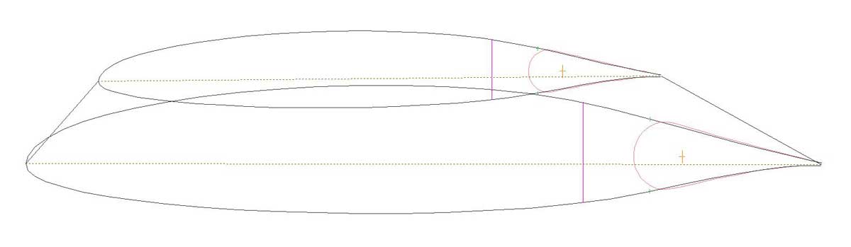
[September 14, 2012]
The faulty mag had evidently had a coil failure. The coil, which carried a stamped date of 1981, had been left in place when the mag had its 500-hour inspection just a couple of months ago. It was not covered by the warranty. I found this odd, but the guy at the shop explained that coil failures are unpredictable, not particularly correlated with age, and that to routinely replace coils would nearly double the cost of the inspection without necessaily serving any purpose. I suppose I can see the logic of that. On the last day before Nancy and I left for a 3-week trip to New York, Cambridge and Cape Cod (we seem to be becoming habitually bicoastal), I reinstalled the repaired mag, timed it and did a run-up, but did not have time to fly. We are now back, and I'm going to go out to fly it today, although the forecast temperature at the airport is 102.
When we landed at LAX yesterday the airport was under one of those strange fog banks that leave one half of a runway in the clear and shroud the other in mist. We taxied past a Korean Air A-380, and I was struck by the gull-wing-like distribution of dihedral. I suppose in order to keep the landing gear trucks short and the engines above ground, the blimp-like fuselage sits low and the wing inner panels angle rather steeply upward. The outer panels are more horizontal, or at least appear so; when they're full of fuel they sag, and it's hard to judge how they would look in flight.
[August 20, 2012]
On runup today I found that my left mag was completely inop. This must be why old-timers check their mags after landing. Tomorrow I'll take it to the shop that recently overhauled it. Had lunch with Jerry Slocum and Mike Melvill; Mike's Long-EZ, he said, has more than 4,000 hours on it. It looks beautiful, and brand new, but it's more than 30 years old.
[August 15, 2012]
Prices for the 20 amp-hr Yuasa batteries I use are all over the map, but I found a couple for $60 (each) at Amazon. Yesterday they arrived and today I installed them and put them on a slow charge.
Replacing the batteries is quite a big production, because first they have to be filled with acid -- they come dry -- and the acid (sulfuric, dilute) did not come with them. I started out by buying two boxes of the stuff at an AutoZone store near the airport. When this turned out to be insufficient, I went back, only to learn that a gentleman had just bought their last two boxes -- that gentleman being I. I found another box at another store -- AutoZones are all over the place here, like Starbucks -- and finally got the fluid into the batteries without spraying too much on my hands and in my eyes.
Getting the batteries into the plane is the next problem. Their terminals are rectangular lead cages with a nut inside. The machine screw that engages this nut is a little too short, and I always end up having to shim one or two of the nuts up with cardboard to get them to engage with the screws. I noticed at AutoZone that they carry a motorcycle battery dimensionally similar to mine, and with a similar model code, but sold under the name of "Duralast". They were $60 too, and came with their own supply of acid. Maybe I'll try them next time, if I don't hear something awful about them first. I've observed that one of the laws of marketing seems to require presenting as a virtue your product's principal defect; thus, I am inclined to suspect that Duralast batteries would last less long than other types.
Several people have suggested that I use a different type of battery, for instance a gel cell; but the battery box, which is pretty much integral with the cowling, is built around these particular batteries; any replacement would have to have exactly the same dimensions.
[August 8, 2012]
Yesterday I flew down to Torrance to meet with some people connected with a South African kit and LSA manufacturer called The Airplane Factory. They make 2- and 4-seat versions of a low-wing all-metal design called "Sling", and have flown both versions around the world. From Torrance a bunch of us flew in three airplanes -- a Sling two-seater, a Brazilian Samba "motorglider", and Melmoth 2 -- over to Catalina Island for lunch. Mike Blyth, one of the company's founders, rode with me. After lunch the other two planes took off, but Mike and I found ourselves stuck on the ground; Melmoth would not start. In fact, it would not turn over. In fact, the voltmeter read nine volts, and dropped to near zero if I pressed the start switch. This was puzzling, since the batteries are quite fresh and the starter had cranked powerfully on the day's two previous starts.
Electrical problems are particularly annoying, because they are often hard to understand, hard to locate, and impossible to see. The first thought that goes through one's mind in a case like this is a bad ground, possibly corrosion at a battery terminal. We cleaned up all the battery connections, without effect. Finally, directed by the sympathetic fellow manning the Unicom, we located a start cart, which consisted of an old stick-shift pickup with a couple of batteries in back and 12 and 24-volt outlets on the front bumper (where I would never have found them, had Mike not thought to look there). Melmoth has an external-power socket -- it has been used many times -- and now it started right up. Keeping the engine running, I dropped Mike at Torrance with an emphatic (and unnecessary in this case, since he is very experienced with airplanes and propellers) briefing to go off the trailing edge of the wing and stay away from the propeller.
Voltmeter and ammeter readings were normal during the flight. After shutting down at Whiteman I tried to restart and got the same result as at Catalina -- that is, no result at all. The voltmeter again indicated low and dropped to almost nothing when I pressed the start button. I checked the voltage at the battery terminals; 25.4, which is normal immediately after shutdown. During the flight, however, I had noticed that two electronic devices with reset buttons, the GPS and the fuel totalizer, had to be reset several times. This suggested momentary power interruptions. Suspicion now falls upon the master switch and the master contactor; I will check them out today.
[later...]
Every time there is an electrical problem, my first impulse is to assume some very exotic reason for it. Then, after I get tired of imagining arcane phenomena never encountered before, I fall back upon the general-purpose "bad ground" theory. That one works a large part of the time. But sometimes the cause is even simpler than that.
Bad battery! One of the two 12-volt batteries that I run in series had apparently suffered some sort of major internal breakdown. It delivered 12+ volts to a voltmeter, but as soon as you put a load on it that dropped to almost nothing. I guess it would be handy if I added a three-way selector switch to the on-board voltmeter circuit, so that you could look at either battery separately or both together. Apparently failures like this occur without warning, however, so I'm not sure that this one could have been foreseen; but at least it might have been diagnosed more quickly.
[August 3, 2012]
The "Driver" cylinder no longer leaks.
[July 27, 2012]
After returning from two weeks on the east coast I resumed my overhaul of the auxiliary cylinder on the flap controller (labeled "Driver" here). The telltale paper towels that I put under hydraulics to detect drips are always pink under this cylinder, whose function is to make sure that when the flap retracts all four actuating cylinders end up back at their initial extension. It's a single-acting cylinder -- it just pushes, doesn't pull -- and although I could not find any obvious source of leakage when I took it apart (on July 9, just before I left) I decided to replace the aluminum piston with a steel one on the principle that one ought not to have an aluminum piston running in an aluminum cylinder if it is not immersed in fluid on both sides. Yesterday I rough-machined the new piston; today I will attach it to the shaft, finish machine it, and, if all goes well, assemble the cylinder and install it in the airplane.
If it still leaks, suspicion will fall upon the hose; but leaky high-pressure hoses are rare indeed. A few weeks ago I looked at a small HD color video camera to replace my now rather outdated low-def black and white one. It is slightly larger than my present one (which is about the size of a sugar cube) but color would make it easier to see something like a drop of hydraulic fluid forming on the underside of a cylinder or hose. If the cylinder still leaks after this fix, I guess the next step will be to make a movie about it.
[July 5, 2012]
I found some references to cooling-air temperature rise in old technical papers. The three values cited were 120, 130, and 150 degrees F, so the 121-128 range I recorded was at least in the ballpark. They also talk about cylinder head temperatures higher than I allow -- eg 435 F -- and about more demanding cooling scenarios, like a full-power climb; so I suppose the fact that my temperature rise is on the low end of the scale might be related to the fact that I climb at 65% power and cruise at 55%.
I have wondered whether it really makes much sense to climb at reduced power. Rate of climb is directly proportional to excess power, and the engine is more efficient at higher power settings than at lower ones; so it would seem that at any given indicated airspeed I might as well climb at the highest power setting consistent with good cooling. The only argument in favor of spending more time in the climb is that it means spending more time at the most efficient angle of attack.
[July 3, 2012]
I moved my high-tech backyard chef's RF meat temp probe to the hot side of the baffles in order to find out the temperature of the outgoing cooling air and also the temperature of the throttle environment during long periods of idling.
| Altitude | OAT C, F | Cowl temp | Rise | Remarks |
| Ground | 28, 82 | 68, 154 | 40, 72 | After runup |
| 5,000 | 23, 73 | 83, 181 | 60, 108 | climbing at 105 kias, 50 lean of peak, cowl flaps open 1" |
| 7,000 | 20, 68 | 87, 189 | 67, 121 | |
| 9,000 | 18, 64 | 89, 192 | 71, 128 | |
| 11,500 | 14, 57 | 81, 178 | 67, 121 | cowl flaps open 0.5", 140 kias |
| 11,500 | 13, 55 | 79, 174 | 66, 119 | cowl flaps closed, 138 kias, 27/2300; hot cylinder 175C/350F |
| 11,500 | 13, 55 | 81, 178 | 68, 123 | 30/2300, 144 kias |
| 9,000 | 17, 63 | 71, 160 | 54, 97 | descending, 160 kias, 23/2300 |
| 6,500 | 22, 72 | 69, 156 | 47, 84 | |
| Ground | 28, 82 | 92, 198 | 64, 116 | 2 minutes after shut-down, cowl flaps open |
During the climb I was adjusting the cowl flaps to keep the hottest cylinder below 200 C (392 F). It's interesting that the upper deck temperature rise seems to stay close to 67 C (120 F) under various cruising conditions. Now I need to dig through my papers on cooling and try to find out whether this would be considered a good temperature rise or not. Obviously you would like to stuff as much heat as possible into as little air as possible, but the returns diminish as the air heats up. It should also be possible to calculate the cooling air volume, since the heat rejection of the engine is known (I think). Actually, you can get that from the delta-p -- the pressure drop across the cylinders -- too.
[June 22, 2012]
Run-up this time was good -- there had been a loose nut on one plug -- and the test flight went fine. I had a distinct impression of more power during the initial climb; I was 1,000 feet agl halfway through the crosswind leg, despite climbing at a nominal 75% power setting. A perceptible increase in power seemed unlikely to me, but I mentioned it to the mechanic who had installed the mags and he did not seem skeptical; he said that ignition harnesses begin to deteriorate after five years or so in use. I don't know whether my Bendix harness was 20 years old or 40, but in any case it was well into the post-five-year phase. I'm not sure, however, what "deteriorate" means in this context. If the harness looks good, has no kinks or chafing, and the leads into the plugs are in good condition, is there any hidden deterioration? Do the wires get tired of the hard work of carrying high-voltage current? Perhaps the conductor migrates toward the shield in tight bends. I don't know.
[June 21, 2012]
Last Saturday an A&P from one of local shops, Able Air, came over to my hangar and installed and timed a pair of overhauled Slick mags, leaving it to me to add the harness. I looked online for tips on how to do this and found none, except the comment that it would take about four hours. What a laugh. It took me four hours on each of three days. Well, maybe three on one of them. Perhaps if you were exactly replacing an existing harness it would take four hours. But the new harness is longer than the old Bendix one, and allows for more natural paths which, in turn, required making new holes through baffles and closing old ones, deciding on new clamp locations, and so on. Not realizing at first that this was the case, I mistakenly thought I should sort out and attach the plug leads first and secure the magneto caps afterwards. In retrospect, this made very little sense. I ended up arranging and rearranging the leads two or three times before getting them sufficiently untangled to tie down. I then had to add the pressurization plumbing and the air filters, which had been removed when I put the unpressurized Bendix mags on in 2003, and finally the tie-wraps and the attendant bloodshed. The last thing I did was attach the P leads. For some reason that I can't remember now -- it dates back to 1997 or so -- I had wired the P leads as full circuits running from the mags to the panel switches and then back to grounds on the mags. This was quite unnecessary; the ground terminal can be near the switch, and should be. But it was at least convenient to attach the ground leads to the Bendix mag cases, which bristle with #10 screws. The Slicks don't have any place to attach a ground lead, so I had to extend them to somewhere else, which happened to be a ground post on the alternator. Actually, now that I think about it, this whole story makes no sense either. In 1997 the Slicks were on the engine -- I took them off and put on the Bendixes after one of the Slicks had a coil failure on the way to Oshkosh in 2003 -- and so when I first installed the engine I must have found a place on the mags to attach the grounds. It's a mystery.
Yesterday afternoon I finally started the engine, which ran, although a bit more roughly on the left mag alone than on the right. So at least the leads are going to the right plugs.
While doing this I was reflecting on the sensations of manual work as opposed to writing. Time passes frictionlessly at the hangar. Sometimes I experience little waves of frustration or impatience, but mainly I remain in a state of absorption that is neither happy nor unhappy, but mindless, if you take "mind" to mean the continuous fretful agitation of the personality that reminds us that we are alive and that we continue to be ourselves rather than someone else. I have gravitated to the mindless state for many years now, spending thousands of hours working on my two planes. I am reminded of a comment in an old New Yorker article that the stream of consciousness of an alligator is probably like a dial tone. Mine is like that when I work; or perhaps a busy signal. To say that "I love the work" would be sentimentalizing it. Perhaps it's just an escape -- but from what? My life is not exactly full of troubles.
As the title of this blog implies, a little inner voice tells me that I have chosen to do mechanical work rather than to "strictly meditate the thankless muse", and that there is something shameful in this. On the other hand, offers a rival voice, perhaps I have simply followed the path for which I was better suited.
[June 13, 2012]
The Australian tech support guy was unable to figure out from the photos I sent him what was wrong with my ultrasonic motion detector, so I got another kit and assembled it last night. This one works, as far as I can tell; I now need to test it in flight. My other ultrasonics project -- the rangefinder that I thought could be used as an airspeed measuring system, completely independent of the pitot -- will not work, I realized this morning, because changing speed will change not only the transit time of the sonar signal but also its frequency, and so the receiver, which is tuned to 40 kHz, will not recognize the return signal. I should have realized that a year ago; I fail more and more intelligence tests these days. I suppose it is some comfort that none of the people with whom I discussed the scheme pointed out this rather obvious flaw in it; or maybe they were just polite. I suppose that an electronically astute person could work around the difficulty with variable tuning and some sort of speed-feedback scheme, but I am unfortunately not he.
I suppose that if I insist on using the ultrasonic rangefinder, which is accurate to 0.1 inch or better, for something, it could be as a very fancy flap or airbrake position indicator or a squat switch.
Later in the day...
Had lunch with Russ Hardwick, talked over the question of the Doppler effect on the ultrasonic airspeed gadget. I was confused; it would not be an issue, because since both transmitter and receiver are moving at the same speed, they compensate for one another. A stationary observer between them would hear the transmitted ping as shifted upward in pitch (assuming it is facing upwind) but the receiver, because of its own motion, would cancel out the shift.
[June 6, 2012]
Rather comically, on my first flight after taping the pre-landing checklist to the panel and adding a window in the nosewheel well through which to verify that the gear is down, I ignored both. Old dog, new tricks.
I had my Slick pressurized mags overhauled and acquired a new ignition harness, my old Slick harness having evidently disappeared, probably with the dissolution of my overhauler, Western Cylinder, after the death of Mike Attolico. I'll have them installed and timed next week.
In the meantime I've been fiddling around with some electronic projects. This is completely new terrain for me. I had gotten an ultrasonic rangefinder (a "Parallax Ping") about a year ago but I didn't understand how to use it; just recently I got a student microcontroller kit called a BASIC Stamp and found an article online showing how to program it to interface with the Ping. Sure enough, it works. If I can successfully desolder either the transmitter or the receiver from the Ping board, I should be able to rig up the experimental electronic airspeed indicator I wrote about a year ago. I also got a DIY ultrasonic motion detector that I hope to use as a ground proximity sensor; the idea is to trigger a landing gear warning if the plane is 20 feet or less from the ground and the gear is not down. So far it refuses to work and after a few initially promising emails the product support guy in Australia has fallen silent, perhaps after seeing the photos I sent him of the assembled board. I hope he eventually returns to my aid.
[May 17, 2012]
On Tuesday I flew up to Tehachapi with Jerry Slocum, an old friend from Melmoth 1 days, for lunch with Mike and Sally Melvill. On the return flight to Whiteman, we had a near escape from disaster. We were on short final, at maybe 100 feet, when someone in a Skyhawk holding short for takeoff called the tower to say that our gear was not down. I put it down and we landed uneventfully. But if that guy had not been holding there, and had not paid attention to the landing airplane, I would have seriously damaged the airframe, engine and propeller.
Naturally I have thought a lot about how this happened. Usually mental failures of this kind are connected with deviations from habitual patterns or with unexpected, distracting external events; but there had been none. The approach was the usual straight-in from the Newhall Pass. The normal sequence of events is to slow from 130 or 120 kias four or five miles out by opening the airbrake. At 100 I lower the gear and extend 10 degrees of flap. I trim to approach speed, turn off the fuel tank auto switcher, open the cowl flaps, put the prop in fine pitch, make sure the mixture is rich, and open the wastegate fully. All this is usually accomplished by the three-mile call. I go to full flap at about one mile.
On this occasion I somehow missed the gear-lowering step. That is puzzling in itself. I can't account for it, and I can't think of what I could do to prevent such a mental slip in the future.
But what is odder still, and what I can do something about, is that I have a clear memory of checking that the gear was down, and believing that I saw the indication that it was. As Jerry said, it was a case of seeing what I expected to see. The gear up/gear down indication consists of two labels on a large torque tube near the floor on the right side of the cockpit. One label says "GEAR UP" and the other simply says "DOWN". Both have bright aluminum-tape pointers that align with a fiduciary mark when the gear is either up or down. All three gears are mechanically interconnected, and so the position of this torque tube signals the state of the entire landing gear.
What I now understand about this system and how I relate to it is that I have always used it to check that the gear has cycled fully. That is, I have paid more attention to the alignment of the silver arrow and the fiduciary mark than I have to the words UP and DOWN. When I glanced at it on this approach, I verified that the marks lined up -- but I evidently failed to register the fact that the nearby word was UP and not DOWN. (Actually, the word UP is partly eclipsed by the arrow, an infelicity that I had ignored in the belief that it was clear enough.)
I need to provide a more direct, non-verbal signal of gear position. The simplest would be to put on the torque tube conspicuous red and green stripes that would rotate into sight as the gear went up or down. That would be a simple improvement that would eliminate the need to actually read a word and grasp its meaning. It would also be quite easy to add a microswitch, or two microswitches, that would light up red and green lights on the panel -- though lights are surprisingly easy to ignore. The most complex arrangement, and most similar to those in production airplanes, would be to combine those microswitches with a third on the flap actuator starwheel, or to use a motion detector to sense the proximity of the ground, so that the combination of full flap or ground proximity and retracted gear would sound a buzzer.
No system is perfect, witness the gear-up landings that occur in airplanes provided with all sorts of ingenious lights and buzzers. But I now realize how imperfect my present system is, and how much it relies upon a certain quality of alertness and attention on my part. I gave myself enough of a scare that it will probably be several years before I backslide to one casual braindead glance at the torque tube to verify gear position; but at any rate it seems important to add some conspicuous color to it right away.
Another thing that might be wise would be to put the pre-landing checklist on the panel. I never use the paper one on my kneepad, always relying on memory, because pre-landing is such a busy time that consulting the checklist seems cumbersome. I'm not sure I would use it if it were permanently on view, and it would certainly not prevent such primitive errors as looking at the word UP and not noticing that it was not DOWN; but it might add a small extra margin of reliability.
Thinking about intercooling, I collected some temperature data. It was a warm day, OAT 18C above standard. I had a temperature probe installed where the throttle body will be if the manifold is reversed, and there is a built-in induction air temperature probe at the end of the left log manifold. The IAT probe, which is simply an AN oil temperature probe, has always indicated implausibly high -- around 100C; it seems that it is actually reporting the temperature of the aluminum manifold, not the air inside it. Here are the temperatures I recorded (all Celsius):
The OAT gauge, which is digital, is acting up and practically unreadable, so the OAT numbers may be off; they certainly don't display the expected lapse rate of 2C per 1000 feet, but it wouldn't be the first time Los Angeles had an inversion. The IAT numbers are obviously suspect. The cowl temperatures make sense, since the air at the place they are being measured, high up behind the engine, has passed by the exhaust pipes and the turbocharger to get there. The purpose of collecting this information was to help decide whether an intercooler, if I were to install an intercooler -- which is by no means certain; that's a separate decision -- could use internal cowling air or would require a separate outside air inlet.
By the way, specialists are fond of insisting that "intercooler" is a misnomer, because intercoolers are properly heat exchangers placed between stages of multiple-compressor superchargers, and that the proper term is "aftercooler". This seems like a display of erudition for its own sake -- a crime of which I am often guilty myself -- because the "inter" could just as well mean "between the compressor and the throttle" as "between one compressor and another." Besides, for etymological parallelism, "aftercooler" ought to be "postcooler", though "tc" doesn't roll off the tongue quite as nicely as "rc" does.
Anyway, the real question is not what it ought to be called, but whether or not it's worth having. I ran some rough numbers and concluded that the additional heating burden created by compressing air at 18,000 feet is about 10% of the engine's natural heat rejection. If you can keep the CHTs down with the existing cooling flow, then the only reason for the intercooler would be detonation margin. Unfortunately that is something I know next to nothing about. At 30 in. Hg at 18,000 feet, the turbo output is at 175F or so; rather hot.
The engine began to feel slightly rough at 14,000 feet and 2,300/27; if I increased the rpm and reduced the manifold pressure, it smoothed out. This did not feel like cross-firing due to unpressurized magnetos, which manifests itself as random small jolts, but at any rate I am thinking about replacing my unpressurized Bendix mags with pressurized Slicks. They were on the engine when I first flew this airplane, and I replaced them with the Bendixes -- stored ever since I installed the turbocharger on Melmoth 1 in 1980 -- after one of the Slicks had a coil failure en route to OSH in 2003.
[April 30, 2012]
The end cap bore having been enlarged by .006, the wastegate passed the latest flight test without any problem. Now it has but to stand the test of time.
[April 24, 2012]
I turned the wastegate spool down to .738, put it back on the plane, and flew it today for the first time. The test was generally successful. The turbo seems to be able to deliver more pressure at lower rpm than it used to; if this is true (my first impressions, which include the recurrent feeling that my car's engine runs better after I clean the windshield, are often not borne out by later experience) then it is most likely due to the improved breathing of the larger, three-necked banjo box. The wastegate spool worked during most of the flight, but it seized during the descent. On disassembly, which required a hammer, it was evident that the spool shaft had galled in the end cap bore, most likely because the end cap cooled faster than the shaft did. Enlarging the end cap bore a bit should take care of that.
Here's what the thing looks like in place:
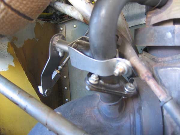
[April 19, 2012]
The wastegate is now installed, but on the first ground runup it stuck at about 45 degrees of rotation. It is typical of me that I would rely on intuition to select my clearances, and only do the required (and very simple) calculations after my guess turns out to be wrong. So after yesterday's unsuccessful test I at last checked the coefficient of thermal expansion of stainless steel. The spool (the rotating part with the blade or butterfly at the end) is 3/4" in diameter, and would expand by about 0.012" at the peak turbine inlet temperature (1650 F). The tube inside which it turns (the "boss") gets hot too, of course; if it were at the same temperature it would expand by the same amount and clearances would be preserved, but it is exposed to cold air and so expands less. I found some data online about auto exhaust surface temperatures at full-throttle operation; they suggested that the boss might get up to only 800 or so, in which case the differential expansion would be .006. The current difference between the boss bore (.750) and the spool diameter (.746) is just .004, so I obviously have to take off a few thousandths more. Just to complicate matters, there must be a temperature gradient along both the spool and the boss, so I am working with a lot of unknowns and will have to proceed a little bit at a time.
Here is the complete wastegate. The bellhorn to which the vernier push-pull cable attaches is still missing, because we won't know how long it can be until the assembly is in place. Mike is coming down tomorrow for a fitting. The valve spool is retained by a cap about the size of a quarter, which in turn is held in place by a stainless-steel band secured on the back side of the bypass tube with a single bolt (see the drawing lying under parts in next picture down). The design is intended to make disassembly easy. In the exhaust system, even stainless steel parts eventually accumulate a layer of crud, which can be removed by a light scouring with emery paper. I'm hoping that regular cleaning will help keep the wastegate working smoothly.
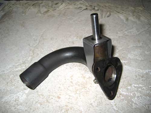
[April 12, 2012]
Mike Melvill, who apparently got his taxes done early, decided to go ahead and make the rest of the parts for my adjustable wastegate. In the picture below, the spool is an aluminum test article for the milling-machine program. The real spool is 321 stainless steel.
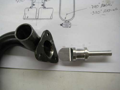
The original design, reflected in the sketch lying under the parts, had called for a piston ring sealing the spool against the "boss" -- the short tube sticking out of the side of the J-shaped one. (A picture of the whole thing in its original, non-adjustable form is below.) I didn't know the dimensions of the piston ring yet, and we decided to go ahead without it, and instead to provide two flanges between which some sort of glass or ceramic packing would be wound. The blade-like portion of the spool is the butterfly:
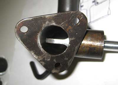
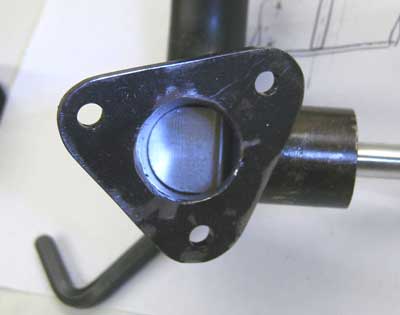
The butterfly appears too short in the right hand image, but that's a trick of the light on its generously-radiused base. The full diameter of the spool actually does not intrude into the bypass duct.
I have not gotten my taxes done yet, and so this is not going to be installed before next week.
[April 6, 2012]
The air filter box and triple-duct banjo box are now in place, as is the vernier cable for the wastegate. Mike Melvill volunteered to machine out the plug in the wastegate, which was galled into place, and to ream it to .750. My neighbor says he'll have the butterfly done this weekend. Making allowance for unexpected developments and for the Rule of Three -- which states that a job will take three times as long as you expect, even if you take the Rule of Three into account -- I may be able to fly in a couple of weeks.
[March 29, 2012]
Advancing on three fronts, I have nearly finished the new banjo box for the turbo air inlet, partially machined poppet valves for the main gear oleo orifice plates, and partially destroyed the fixed wastegate assembly. This last item, while not directly constructive, may be viewed as the sort of bridge-burning gesture that leaves one no choice but to go forward.
My oleo maven has become interested in instrumenting my landing gear in order to measure deflection, rebound, acceleration and so on, but since it makes sense to get data for the stock oleo first, I won't be doing the orifice modification right away.
As for the wastegate, my next-door neighbor, who has a machine ship in his garage, had some 3/4-inch 303 round bar stock and volunteered to machine the butterfly for me. I am now waiting for him to do so; I don't feel that I can rush him, but in a few days I may begin mumbling the word "grounded" in subliminal tones. I found a usable vernier cable among the decades' worth of precious stuff, read "junk," in my hangar. It's a crummy-looking thing, probably a 40-year-old mixture control from a 172 or something like that, but it's the right length and a different color and shape than my mixture vernier -- it's good to differentiate things. I was wrong, by the way, when I wrote on March 16 that the tee pipe is smaller than the bypass pipe; they have the same O.D., and so it will be possible bore the tee out to 3/4 I.D. and therefore to fully shut the wastegate -- not that that is necessarily a good thing.
Tomorrow I plan to do the final layups on the new three-duct banjo box, which looks like some sort of artificial heart:
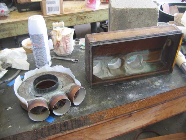
The thing next to it is the air box, which sits below the filter. The triple ducts are 2.25 in. in diameter; for years I have made do with a single duct and a considerably smaller banjo box, but it probably rendered the turbo somewhat asthmatic. That didn't matter so much when I didn't have a proper wastegate, but once I can make full use of the turbo it should be better to let it breathe more freely. We'll see.
[March 20, 2012]
A couple of weeks ago someone suggested that a good way to inflate the main gear oleos equally was to put a tee on the strut pump output and inflate them both at once. This sounded reasonable and so I did it. Fortunately the modification was cheap, because it didn't really work. For one thing, if one strut was a little taller than it should be, it would not come down; the air valve is one-way. But that's not a big deal; you have to bleed air out of an overinflated strut anyway. (Struts get overinflated seasonally, when rising temperatures make the air or nitrogen in them expand.) The real problem is that when you inflate a strut you are not adjusting the pressure, only the piston extension. Once the piston starts to emerge, the pressure remains constant; it is simply the load on the strut divided by the area of the piston. The amount of piston that is exposed becomes a function of the amount of space in the oleo that is not occupied by hydraulic oil. So if the struts are not identically charged wth oil, they will not extend to identical heights. Not that it matters, unless they're wildly out of whack. But the whole point of the exercise was to get the struts equal, and, because I had used different methods of filling the two struts and they didn't contain identical amounts of oil, it didn't really work that way.
Another complication arose yesterday when I needed to add air to my nose strut. It's necessary to close one branch of the tee in order to pump up a single oleo, so I would have to add a petcock on one side. Considering that this well-intentioned trick was intended to be a simplification, it seemed to be getting more, rather than less, complicated.
I may have a chance to equalize the fluid levels in the struts in the not too distant future, however, because my oleo strut consultant has proposed that I replace the fixed orifices in the struts with ones incorporating check valves that would uncover additional orifices during the compression stroke. These would have less damping on compression and more on rebound, which is to say that they would provide squishier landings with less bounce. Not that I have ever bounced a landing in this airplane; it's such a floater that even a bad landing amounts to nothing more than a stiff tap. But you can see that any bounce in landing gear is bad, and so very high rebound damping is desirable. Javier Arango, who owns a Corsair, told me the other day that its landing gear has virtually no rebound at all; it squishes down on a hard landing and then just oozes back up -- clearly preferable to Cessna-like springiness when landing on a carrier. This would be a very simple modification, and I am inclined to do it as a matter of principle.
[March 16, 2012]
I made a plug for the new banjo box for the turbo inlet, but I probably won't get around to laminating it until next week. I also thought some more about the wastegate. This is what the present one looks like:
The bent bypass tube is 7/8" in diameter, with an I.D. of 3/4". The tee entering it from the left is 3/4" O.D. The present "gate" consists of the threaded bolt (secured by safety wire) that screws into the tee from the left; it has a bullet-shaped end that partially blocks the bypass tube. The idea is to replace this fixed obstruction with something adjustable. I thought a butterfly, but my machinist friend Homer, who is something of an expert on engines, didn't seem enthusiastic about that idea. I got the feeling that he thought that small parts operating at very high temperatures can be troublesome. He suggested replacing the fixed bullet with one that slides in and out. But he has not seen the engine in real life, and did not realize the space constraints surrounding it. As far as I can see, the only way for the push-pull cable to get to the wastewate is from above and inboard, and at a right angle to the tee pipe. My latest proposal to him (upon which he has not yet commented) combines the rotation of the butterfly with the massiveness of the bullet:
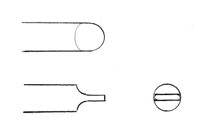
This is basically a butterfly, but with no issues of securing it to a shaft and with a big heat sink attached to it. It would be a loose fit in the tee pipe -- maybe .005 radial clearance -- and could have a piston ring for sealing, though I'm not sure that would be necessary because it will expand somewhat relative to the cooler tee pipe. Because the I.D. of the tee is less than that of the bypass tube, there would be a small segment-shaped leak on each side of the bullet when it is closed; but there can be a bootstrapping problem if a wastegate seals perfectly, so perhaps that wouldn't matter.
[March 13, 2012]
As part of my effort to delay indefinitely the day when I take a hacksaw to my $1,500 Continental intake manifold, I started working on increasing the size of the air duct leading from the air filter to the turbocharger. My present scheme, which may succumb to practical difficulties as I implement it, is to add two more SCAT ducts going from the inlet air box to the banjo at the turbo inlet. The big difficulty here is that I put the turbo air inlet too close to the firewall, and so the banjo can be only about 1.5 inches deep. A single 3.5-inch duct would be nice, but won't fit. Three separate 2.25-inch ducts are not an ideal solution, but they are bound to be better than one. Resistance is a function of flow speed, and so tripling duct area should reduce resistance by a factor of nine or so.
After ignoring the subject for years, I took another look at the wastegate. The present wastegate is the fixed one from the Piper Arrow and Seneca; designed for absolute simplicity of manufacture and operation, it is really just a fixed leak that limits exhaust flow to the turbo with the unintended consequence that at lower altitudes the turbo is usually blowing against a partially-closed throttle. It's okay for middle altitudes, but not very good higher up. I wanted to replace it with a butterfly. Homer Knapp, my machinist friend whom I trust for advice about such things, suggested a loose-fitting sliding plug instead, with a piston ring at one end. The thing will be manually controlled, and so it needs to offer as little resistance to adjustment as possible.
I checked compressions for the first time in a couple of years. I don't put much stock in compression tests -- if you look at them over many years for the same engine, they wander all over the map -- but it was nice to see that at 1,200 hours all of them are still 76/80 or better.
[February 21, 2012]
Some combination of 1) overhauling the struts, 2) getting the fluid levels right, 3) getting the inflation levels right, and 4) retracting the flaps during rollout seems to have eliminated the "sagging strut" problem. That took way too long -- on to something more interesting!
[February 18, 2012]
Two hours indeed. Actually, it took me four and a half hours to overhaul the left main strut, repack the wheel bearings, and put everything back together again. Some of that time was spent cleaning years' worth of grime from the gear, however, and some making new tools and re-discovering which old ones to use, and some going to buy more hydraulic fluid, so I think the whole job really could be done in three hours or less by a well-organized mechanic. Since it needs to be done only every few years, you forget all the tricks in the interval. Removing the gear from the airplane and replacing it is quite simple, and dismantling the strut itself takes just a couple of minutes. I found that the main O-ring that seals the sliding piston was twisted, but it still seemed to be sealing all right. O-rings are remarkable things. It may, however, have been increasing "stiction" in that strut. I set both struts to 2.7 inches cylinder-to-fork, but this morning I re-read the pertinent page of the owner's manual and saw that it's supposed to be just 2 inches. I guess I've had my struts over-inflated all these years. The manual doesn't say at what weight the struts should be showing 2 inches; I assume it means something like half-full tanks (for a Cherokee) and no people inside, since that might be the typical condition of an airplane in the shop.
One thing I didn't do, and should have, was replace the brake pucks; but they still have some life left. They're currently at 0.175 inches; the rivets meet the disks at 0.125.
To fill the strut, I made a special tool consisting of an AN816-4 pipe-to-flare fitting with a 2.5-inch long 3/16" OD aluminum tube pressed into the pipe-thread end. This is inserted in the normally plugged hole at the top of the strut, and a hose goes from it into a can of hydraulic fluid. The strut is then slid in and out a few times, drawing fluid in and expelling it by turns, and ending with the strut fully compressed. The effect of the extension tube is to preserve a couple of inches of airspace at the top of the strut, as required. (The reason this tool is needed for my struts, and not for unmodified Cherokee struts, is explained at January 5, below.) This operation could be performed in situ if there were a small hole in the wing skin above the strut, but it doesn't seem as though one needs to add fluid to the struts that often. If you have to add fluid, there's a leak, and so you might as well pull the strut and fix the leak.
People often say that struts should be charged with nitrogen, but I prefer a mixture of 78% nitrogen with miscellaneous other gases.
[February 16, 2012]
I was supposed to fly with Jerry Slocum, an old friend, to Tehachapi to have lunch with Mike and Sally Melvill, but a brief storm went through yesterday and left behind it 35-knot gusts at a right angle to the runway; so we took a rain check. Jerry and I went to the Whiteman restaurant and talked for almost four hours about old times, mutual friends, the Airbus vs Boeing controversy, travel, ageing, and various other topics. After he left I decided to overhaul the left main gear strut. This time, having learned one or two things from doing the other one, I was able to remove the strut from the airplane in half an hour. The whole operation shouldn't take more than two hours, if nothing turns out to be wrong. I'll replace the brake pucks while I'm at it; I should have done that on the other side too.
[February 11, 2012]
We came back last Tuesday from two weeks on the east coast. On Thursday I did a circuit of the pattern to test the theory that retracting the flaps during the roll-out would reduce the tendency for one main gear strut or the other to remain excessively extended. The experiment was inconclusive; the weather was quite warm -- around 80 -- and both struts were over-inflated to begin with, the left more than the right. I remembered to use the airbrake this time, so at least I now have some video representative of the real landing configuration. The airbrake, which is a board of about 2.25 square feet that sticks out of the belly just ahead of the wing at a 60-degree angle, produces some helpful nose-up trim and also a little extra lift. I use it on landing as though it were a second flap.
I removed the fairing and camera from the left boarding step and will put them on the right in order to see how well the right main gear doors are closing.
The problem of bending tubing to connect the existing intake manifold to a throttle body mounted at the back of the engine turns out to be more of a challenge than I first thought, but it finally dawned on me that there is a simple solution: SCAT or SCEET hose, the type with an internal liner that smooths airflow.
I have also been thinking about the $30 ultrasonic rangefinder that I got a while ago when I was musing upon alternative ways to measure airspeed. It occurred to me that it could also be used as a squat switch; the gear would not retract when the belly of the plane was, say, four feet or less from the ground. (You'd have to have an override switch, of course, in case it malfunctioned.) The problem for me is that this rangefinder is not a turnkey device; it requires one to supply a circuit to convert its output pulse duration, which is proportional to the time of travel of the sound from the emitter to the reflector and back, to a digital form. No doubt this interface presents no difficulty to the electronics hobbyist, but I am not he. I have to call the manufacturer and see whether he is willing to be helpful; some are, some aren't.
[January 21, 2012]
I posted an edited version of the flight test video here. The quality is not very good -- I need to get a newer spy camera -- but the general impressions are clear enough.
[January 20, 2012]
Yesterday I attached a little video camera to the left boarding step to find out how well my gear doors are closing. The last time I tried to do this, several years ago, the step strut vibrated so violently, and at just the right frequency, that the set screw holding the lens in the camera backed out and the lens disappeared shortly after takeoff. The strut is rectangular in section, and vibrations like that are usually due to vortices being shed from alternate sides in rapid succession. This time, I made an airfoil-shaped fairing around the strut with foam and aluminum tape. It still vibrated, but not to the point of dismantling the camera (for which I got a new lens). I was also interested in observing the behavior of the left main landing gear strut, since I have become convinced -- actually, it is obvious, now that the scales have fallen from my eyes -- that the "slumping strut" problem was not a slumping strut at all, but rather a sticking, and perhaps slightly overinflated, strut on the opposite side. The test consisted of a single flight around the pattern, with the downwind leg extended about three miles so that I could accelerate to cruising speed.
As far as the landing gear doors are concerned, the camera could see only the left and nose gear doors; I will have to put the camera on the other side to see the right doors. After retraction and during initial climb, the doors are not perfectly closed, but they are satisfactory; at 145 kias, which would be a typical indicated airspeed at cruise, they bulge out slightly. The worst gap, around 3/8 of an inch, is at the lower half of the outer door, which seems to flex outward. It is a simple 1/4-inch thick sandwich of carbon and glass; I could stiffen it with some simple ribs. I doubt that the drag penalty is very great, but I would like the doors to shut nicely for aesthetic reasons at the very least.
As for the strut, it was interesting to see that the left main seemed to remain somewhat overextended for a long time after touchdown. On seeing the tape, it struck me that this problem, which began to manifest itself about a year and a half ago, might be related to the flaps, which relieve the weight on the gear after landing. Furthermore, to reduce lift I usually move the stick forward once the nose gear has touched the ground; this, too, has the effect of lifting the tail and slightly relieving the main gear loads. I also am in the habit of braking rather hard, because I like to turn off at the taxiway that leads to my hangar and not have to back-taxi to it; and hard braking puts a load on the strut that increases friction and makes it move less freely. It seems as though the solution to this problem might be some combination of 1) carefully ensuring that the main struts are equally inflated; 2) retracting the flap during roll-out; 3) not braking harder than necessary; and 4) not pushing the stick forward during roll-out.
[January 14, 2012]
Jon Karkow pointed me to a Piper owners' forum where there was a discussion of slumping struts on Cherokees. So it turns out this problem is not confined to me. Participants gave various explanations, one suggesting that the problem is not the right strut collapsing, it's the left strut remaining excessively extended after landing because of "stiction" or starting friction (which is greater than sliding friction). So maybe I need to overhaul the left strut as well.
[January 11, 2012]
Shot a coupled ILS approach to Van Nuys; very calm day, and it worked nicely. Then I returned to Whiteman and landed, and to my amazement and very great disappointment as I turned left off the runway the right strut compressed in the same way as before I overhauled it. Complete bafflement.
[January 6, 2012]
With much spillage, since I did not have a proper funnel and was pouring from a 1-quart can into a 3/8-inch hole, I got the oleo filled to something like the proper height with hydraulic fluid and reinstalled it in the airplane. Now I just have to understand why having too much fluid and not enough air in it was having the observed effect. I cleaned and repacked the wheel bearings while I was at it. It's never clear to me why this is necessary; a car goes tens of thousands of miles between wheel bearing services; an airplane rolls only a few miles a year.
[January 5, 2012]
Nothing was wrong inside the oleo. The cause of the problem has to be an incorrect amount of hydraulic fluid. I moved the air valves when I modified the PA28R struts for Melmoth, and so can't use the Piper method for adding fluid, which involves overfilling and then compressing the strut to force excess fluid out the air valve. The problem is that without the air valve being in its original position, about two inches below the top of the cylinder, there is no convenient way to set the height of hydraulic fluid inside the strut. There is an inconvenient way; a 1/8" pipe thread plug in the top of the strut can be removed, and fluid sucked out through a straw, as it were, to the proper depth; or a special temrporary plug could be inserted with a tube extending two inches into the strut, and the strut filled, extended, and then re-compressed, forcing fluid out that tube and preserving the proper amount of air in the strut. Unfortunately, this top plug is inaccessible when the strut is in the wing. I guess I could drill a hole in the skin above the strut to get at it. Another possibility would be to take the air valve and insert a bent tube of the proper length with which to suck out excess fluid; but I'm not sure there is room inside the oleo to feed in a bent tube at that location. Another possibility would be measurement: determine the volume of hydraulic fluid required to fill the strut, and put in just that amount. That, however, would require completely emptying the strut to start with, and that can be done only by removing the piston from the cylinder -- possible, again, but not exactly convenient. Fortunately, the oleos hold air and fluid indefinitely, and so replenishment is a rare event. For the time being, I will do nothing, since with the strut out of the airplane I can remove the top plug and get the fluid level right.
[January 4, 2012]
I took the right main strut off the plane today to overhaul it and perhaps to discover the cause of its strange tendency to compress on turning left off the runway after landing and then gradually to re-extend while taxiing. The fluid was very dirty, but apart from that the condition of the inside of the oleo was unremarkable. There was some superficial corrosion on the unpainted, exposed top of the cylinder; not bad, considering that this strut was assembled more than 20 years ago. I'll clean it up and chromate or alodine the exposed parts before re-assembly. I bought two rebuild kits in order to motivate myself to overhaul the right strut as well, but I did partly dismantle it and replace a couple of O-rings just a few years ago and so I will probably end up stockpiling the rebuild kit until the right strut begins to act up.
[December 20, 2011]
For some time now I have not left the battery tenders continuously connected to the batteries, and the battery water level has stayed put, surpporting my suspicion that the water had been evaporating not because the batteries were too hot in flight, but because they were too warm during the much longer periods spent parked in the hangar. I have searched in vain on line for mention of battery tenders cooking away battery water (or of my specific type -- the brand name is Schumacher, I believe -- doing so) and have not found anything.
My hope of getting the intake manifold modification done during November was vain; the month came and went without much being accomplished, and now, in the most accomplishment-free month of the year, nothing will get done until January. I have been studying drawings of the engine and trying to figure how how best to route the 2-inch tubes running from the throttle body to the log manifolds. The problem is how to get around the oil filler neck on one side and the starter motor mounting flange on the other, while keeping the two branches mirror images of one another. No doubt there is an infinity of possible solutions, serpentine or tortuous in various degrees, but whatever combination of bends I come up with I have to be able to describe to the tube bender with a reasonable confidence of his producing usable parts.
Mike Melvill came down to have lunch with me and our friend Jerry Slocum, who was in LA for a few hours on his way back to Salt Lake from a pleasure cruise through the Panama Canal. (Jerry used to go with me in Melmoth 1, many a Wednesday during the late '70s and early '80s, to lunch with Burt Rutan and a few other friends at Reno's cafe at Mojave; he always ordered a patty melt.) Mike's Long-EZ is very well equipped, including WAAS and an Aspen PFD, and we talked about the extreme accuracy of GPS approaches, plus or minus half a meter, and how you could probably make a hard but non-damaging landing in zero-zero conditions, if you had to, hands off, using the coupled autopilot. (Airlines do this all the time; as Jerry pointed out, we have probably all ridden along during practice autoland landings without ever knowing it.) I suggested that the addition of a rangefinder from a camera could provide you with height information as you neared the runway, and you could even manage a flare of sorts. Actually, I think that perhaps modern cameras focus digitally, by looking for sharp edges, rather than by ultrasonic pinging; but our discussion reminded me of the ultrasonic rangefinder I bought a few months ago (for $30) when I was thinking about experimenting with it as a non-aerodynamic way of measuring airspeed. Unfortunately the thing came with no guidance whatever about how actually to use it; it was assumed that the sort of electronic hobbyist who would buy it would know what to do with it. Not me. And now, alas, Paul Lipps has died.
[December 9, 2011]
I made the gadget to turn the oxygen on and off. It pulls the 3/32 cable 2.25 inches, locks overcenter, and when unlatched it releases the cable and a spring closes the bottle valve. The reason for this arrangement, rather than a simple solenoid, was concern that the rapid, powerful action of a solenoid might eventually damage the valve seat. The handle is on the left sidewall, by the pilot's seat.
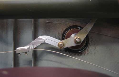
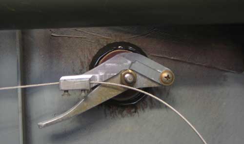
The outlets (there are just two) are between the front and rear seats, on the centerline.
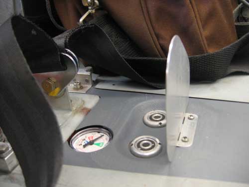
Today I sawed off the leaking fitting (called a "cone") on the 3/16-inch ox line from the bottle to the manifold (visible here) and spent a couple of hours struggling to put on a new one. I tried silver solder, then regular solder, and finally called my friend Homer Knapp, who was stuck in traffic somewhere in Westwood but remained on the phone (it's illegal to use a cell phone while driving here) long enough to tell me that I needed to get some white paste flux at a welding supply store. You'd think I would know stuff like that, but no. Airplanes don't call for a lot of silver soldering or brazing. It was 4:45, getting dark, but there's a welding supply store across the road from the airport (it's where I get my "aviator's breathing oxygen" at a deep discount) and I got some there. It worked like a charm. Actually, super glue would probably have been good enough; the force trying to separate the fitting from the copper line at 2,000 psi is about 81 pounds. Anyway, I'll re-install that on Monday and then the oxygen system will be well and truly done.
The next step will be to determine whether the unpressurized Bendix mags will work at 17,500 feet -- they will probably start arcing -- and then to decide whether to get pressurization kits for them or to install my pressurized Slicks instead.
[November 21, 2011]
I collected some data on speeds and fuel flows at very low power settings. At a density altitude of 7,000 feet and a weight of around 2,000 pounds, I set the rpm at 1,800 and did a sweep of manifold pressures from 17 to 25 in. Hg. with extremely lean mixtures. Below 24 in. Hg there was very little variation. At 17/1800 IAS was 90 kt for a TAS of 100.5 and fuel flow of 3.65 gph. The increase in fuel flow was more or less linear with manifold pressure up to 24 inches and 4.9 gph, where the TAS was 128 kt. Nmpg fluctuated randomly between 26 and 27, reflecting both the flatness of the mileage curve at low speeds and the difficulty of getting precise measurements. Above 5 gph the curve becomes steeper, in part because you have to increase rpm; 28/2300 gives 150 kias, 167 ktas, and 8.8 gph (18.9 nmpg).
[November 19, 2011]
The oxygen system is now working. It took me a while just to decide where to put the pressure gauge (it's in the floor between the seats, alongside the outlets), how to route the 1/8-inch aluminum line connecting it to the bottle, and where to put the pilot's end of the cord that turns the bottle valve on and off. As far as the cord was concerned, I was originally planning to put it with the outlets and the gauge. That would have involved several bends and two or three pulleys. I then experimented with various tortuous paths up the left sidewall before discovering that there is a perfectly straight line from the pulley at the bottle (see picture below) to a point on the left sidewall beside the pilot; it requires no pulleys, interferes with nothing, and is hidden by the existing armrests. Now I have to decide whether I should just put a loop in the end of the cord and bond some sort of miniature coathook to the sidewall, or whether I should go to the trouble of making an overcenter lever to turn the oxygen on and off. I will almost certainly do the latter -- eventually. The plumbing uses a mix of flare and compression fittings and a third type, whose name I don't know, that consists of a hemispherical male element brazed or silver-soldered to a copper or steel tube and a bowl-shaped female receptacle. I first tried flares on the 1/8-inch 3003 aluminum tube; they leaked at both ends. I replaced one with a brass compression fitting; it worked fine on the first try. I wanted to replace the other flare with a similar fitting, but couldn't find one; but I eventually got the flare to seal. Now the only leak, and it is very slow, is at the brazed fitting on the short 1/4-inch copper tube between the bottle and the manifold, visible in the picture below. The male fitting is visibly deformed; I need to remove it and braze on a new one.
The choice of aluminum for the pressure-gauge line was based on weight; copper or steel would be more conventional. The tubing has a wall thickness of .025 in. It is officially rated for pressures up to 2,300 psi, but the tensile strength of 3003-O aluminum is 16,000 psi. Since the bore (0.075 in.) is 1.5 times the total wall (0.025 + 0.025), the tensile stress at the maximum bottle pressure of 2,000 psi is 3,000 psi and the margin of safety is over 5. I think that the reason harder metals are usually used is to resist wear and tear; the aluminum tube does look pretty easy to damage. It is in a protected location, however, and I think I will be able to avoid dinging it. Time will tell.
[November 7, 2011]
Today I flew around for half an hour at 5,000 feet with the engine cranked back to 24/1900, which yielded 5.4 gph or about 30% power. This gave a true airspeed of 130 knots and a specific range (ie gas mileage) of 24 nmpg (around 27.7 smpg). It seems that the airplane falls short of its computed performance at high power, but exceeds it at low. This suggests that the value of e, which is essentially a way of saying what the effective aspect ratio of the wing is, is higher than the computer makes it. In other words, parasite drag is higher than the computer thinks, and induced drag is lower. But it could also mean that the engine's specific fuel consumption (pounds of fuel per horsepower per hour) at low power settings is lower than the computer thinks, or for that matter that the fuel flow instrumentation is not accurate and its errors are non-linear.
The conventional wisdom is that the real best-range speed tends to be higher than the theoretical one because engines are inefficient at low power settings. The next time I fly without a destination, I'll see if I can generate an empirical specific-range curve.
I have been working a couple of hours a day on a system for turning the oxygen on and off from the pilot's seat. The oxygen bottle is in the baggage compartment, wedged under the rear seat footrest (the rear seats face aft). Here is the apparatus, temporarily mocked up with some random twine and fittings.
The fine safety wire securing the pulley is actually not a mockup. It is the final arrangement, and is simply the lightest way I could think of to hold the pulley. It is anchored with a stainless steel cotter key whose legs have been bent outward and trapped under a phenolic disk bonded to the inner skin of the fuselage. I guess I am trying to save a gram here and there to make up for the weight of the oxygen bottle. One oddity is that the bellcrank that operates the bottle's on-off valve has to be at a certain angle, which ends up clocking the bottle so that its built-in pressure gauge faces the floor. I will have to glue a small mirror to the floor to read it. There will, however, be a second gauge in the cabin that the pilot can see.
[October 29, 2011]
The lubrication of the pitch trim mechanism on the 4th was miraculously effective. I have still not flown high enough, nor in cold enough weather, to know whether this new lubricant (which my old friend and onetime Flying Magazine editor Stephan Wilkinson, a former car buff who would get waxes and greases for his yellow Porsche from Germany, recommended and in fact caused to be shipped to me) will stiffen up unacceptably like the last one I tried. Perhaps not; when I put it into the freezer it got somewhat stiffer, but not excessively so. Anyway, now the operation of the trim is positively silky; I feel like changing speed just for an opportunity to use it.
As a first tiny step in the project of reversing the intake manifold, I rotated the vacuum pump 90 degrees in order that its outlet not interfere with the throttle body, which will be above it. I think I will do the manifold modification during November, which is when I have to do my annual inspection anyway.
Yesterday I flew around for 40 minutes just to exercise the plane a bit. When I do this I run about 25 in. Hg and 2,000 rpm with a fuel flow of 6.5 gph at about 5,000 feet d.a. I noticed that my airspeed was 20 times the fuel flow. This puzzled me at first, since that is also the case at my usual cruising setup (170 knots at 8.5 gph) and it ought not to be true at two widely different speeds. It later dawned on me that one (the faster) is true airspeed and the other is indicated. So, in car-compatible terms, it's actually 23 mpg at 195 mph and 25 mpg at 160 mph -- just like our 1986 Camry, but faster.
[October 6, 2011]
I need to remind myself, whenever I'm dreaming up exotic theories to account for electrical malfunctions, to repeat several times, "Bad ground." After taking lots of measurements, all of which checked out fine, I discovered that the fuel gauges worked when I held the piece of the panel that contains them in my hand, but stopped working when I put it back into the airplane. It turned out that moving the wire loom made the problem appear and disappear. Since it affected both gauges equally, it had to be a ground issue -- I believe that is the only wire they have in common. I didn't find the bad connection, but with a couple of tiewraps I stabilized the loom so that the problem went away. There are some malfunctions -- such as the weird noise our dryer is currently making -- that are very difficult to diagnose, but become easy once the failure is complete. I will wait for the fuel gauges (and the dryer) to fail completely.
A huge bubble turned up in the #2 flap actuator circuit yesterday, fortunately on the ground. It may have had some connection with my overhauling the #2 master cylinder in August; why it waited this long to announce itself, I can't say. The hydraulic flap actuation system has been by far the most troublesome thing on the airplane, and I still don't understand some of the things it does. Most of the time it works just fine, but it continues to be plagued with minor leaks and occasional major misbehaviors. Not ready for certification.
[October 4, 2011]
My theory that the high breakout friction in the pitch trim circuit was due to thrust on the jackscrew bushing proved to be incorrect. It was just general dirt and lack of lubrication. I had removed all lubricants a while ago, thinking that they were stiffening up at high altitude and low temperature and making the trim hard to operate. This time I tried a new type of lubricant. I then brought the trim mechanism, which I had removed from the airplane, home and put it in the freezer for a few hours. It was stiffer, but still worked smoothly. So in the end I lubricated everything and put it back together. It feels nice now, but I haven't tried it in flight yet. Another theory of mine, that the weird behavior of my fuel gauges was due to failure of some zener diodes in an interfacing circuit board, also bit the dust. I got the circuit board out and tested the diodes, and they all seemed to be regulating to 7.15 volts, just as they're supposed to do.
[October 1, 2011]
On Wednesday I flew to Santa Rosa to have a look at the participants in the NASA/Google/CAFE Green Flight Challenge. Prizes totaling more than 1.6 million dollars are offered for the most efficient airplane, the minimum standard being 200 passenger-miles per gallon over 200 miles in two hours or less. This is not a very demanding standard if no constraint is placed upon wingspan. Heck, Melmoth 2 with four aboard already gets 100 passenger miles per gallon, and it's optimized for speed, not efficiency. Participation was limited to 18 entrants, but in the event only four were ready. One of these, a powered sailplane modified by Embry-Riddle with a 75-foot-wing and a supplemental electric motor, was disqualified because the university refused to insure its participation in what passed for an "air race." Fallout from Reno. A two-seat Phoenix motorglider of 44-foot span had no realistic chance against the other two, both pure-electric designs of extremely long span and high aspect ratio. So in effect there were only two contestants. The larger of these, the Pipistrel Taurus G4, consisted of two two-seat Taurus sailplanes joined, Twin Mustang fashion, to a centersection carrying half a ton of batteries and a 195-hp electric motor. Here it is in flight:
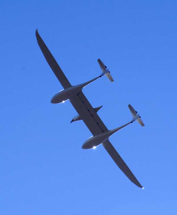
I am inclined to think it will win, simply by dint of having four seats, not that a wingspan of nearly 70 feet hurts. As was the case in the old CAFE races, unreasonable emphasis is placed by the scoring formula on passenger capacity, even though private airplanes seldom fly with all seats full. Peter Lert, who with Gene Sheehan won the first CAFE race in a Quickie Q2, is fond of pointing out that an even better score could have been achieved by a full DC-3, and meals could have been included. The only registered entrant with more than four seats was the bio-diesel powered Synergy, but I doubt that the claims made for its very complicated arrangement of flying surfaces would have been borne out in practice. In any case, it didn't show up. What this contest is going to demonstrate, apart from the fact that most people can't finish a job in time even for a million bucks, is that 200-pmpg airplanes can't fit in taxiways, hangars or tiedowns.
Winners will be announced on Monday.
No trip would be complete without one or two things going wrong. I observed that there is a slow fuel leak where the left outboard flap track bolts to a rib. That should be easy to fix. The fuel gauges, all four of them, have stopped working, and now indicate full at all times. This has to be a problem with the circuit board that provides an interface between the float-type senders and the edgewise voltmeters that I use as gauges. Finally, there is unacceptable breakout friction in the pitch trim circuit at cruising speed. This is nothing new, but I am finally going to try to do something about it. I think it will require replacing the bronze bushing that currently serves as a thrust bearing for the trim jackscrew with a ball bearing.
[September 25, 2011]
After two and a half years or so, a buyer appeared for Ray Henning's beautiful T-18. Ray came down from Seattle for the handover, and I flew up to Tehachapi to see him. It was overcast in the Basin, and I had to hold for about half an hour waiting for a clearance to VFR on top from Burbank. The #3 (center right) CHT went to the top of the green. This is a problem: at the start of the takeoff roll, power is high but speed is low, and so CHTs rise rapidly. If a cylinder is already at the top of the green, it's going to climb out of the green before its temperature begins to drop again. I could not detect any difference in the engine after this episode, so I suppose it did no damage, but an airplane, like a car, ought to be able to idle indefinitely. I am hoping that my scheme of reversing the intake manifold will improve airflow through the cowling by removing the portion of the intake manifold that obstructs the exits. It should also eliminate the problem of rough idling after long holds, which is due to the throttle body, which is the only portion of the fuel system still on the hot side of the baffles, becoming heat-soaked.
[September 21, 2011]
Some friends brought their children over to the hangar to show them the plane. The cockpit miraculously survived having a couple of 6-year-olds sit in it for a few minutes. I then flew around the pattern to show them what it looked like in the air. I offered to take someone along with me, but all declined. The phrase "fiery crash" was uttered several times. Nevertheless, the 3-minute flight was without incident.
[September 19, 2011]
Nancy and I went to Cape Cod on August 26 and returned this last weekend. Melmoth stayed behind, so there has been nothing to report. Before we left, however, I did overhaul the #2 flap master cylinder. My impression that it was leaking through the hollow piston shaft proved to be wrong. I could not find an obvious leak, but I suspected that an insufficiently chamfered hole near the end of the shaft, where a clevis pin passes through it, may have damaged the small (3/8" I.D.) O-ring during assembly. I enlarged the chamfer and polished it vigorously, and also polished out some small scratches and dings in the piston shaft that I had evidently overlooked (or considered inconsequential) when I first installed the system. I did fly the day before we left, and the cylinder seemed no longer to be leaking. But it is too early to be sure.
There was a leak in the static plumbing after I modified it. I eventually located and repaired it, and also added a drainable trap just forward of the right static port. At present it ends with a flare cap, but I should probably replace that with a quick-drain.
I spent a good deal of idle beach time at the Cape face-down in the sand, thinking about reversing the intake manifold. I am determined to do it, even though I suspect that it may turn out to be one of those big modifications that yield no detectable benefit.
[August 17, 2011]
Something worth noticing in the photograph below is that the ridge on the back of the static port is above center. This is not just sloppy work. The hole on the other side is in the center of the disk, but it is drilled at an angle -- all part of my apparently doomed effort to keep water from getting into the static plumbing.
I tried wrapping the #1 cylinder exhaust with the thought that the insulation might keep heated air from entering the baffles. It seemed to have no effect at all. In fact, since the pipe and the head are in intimate contact, I'm not sure that making the pipe hotter is the best way to make the head cooler. I observed that the #3 cylinder is only 10 degrees C. below the #1 -- but 25 to 35 above the others -- so maybe the problem, if it really is a problem, is not related to the rearmost cylinder's baffle. This is all really academic; all temperatures are well within the green. I would just like it if they were all the same.
I decided to get serious about the hydraulic leaks in the flap synchronizer. It's not possible to properly simulate air loads on the flap while on the ground, so I took out the floor panel that normally covers the synchronizer and watched the cylinders as I cycled the flaps in flight. The first leak I found was in the #2 master cylinder; fluid seems to be seeping out through the hollow stainless steel piston shaft. That should be easy to fix by simply pressing in an aluminum plug.
One chronic annoyance has been the proneness of the static system to take on water while parked during heavy rain. I'm surprised this can happen, since the ports are so tiny and are on essentially vertical surfaces, but anyway, it happens, and happened again at Oshkosh, where it was apparent to me as I took off that I was not getting a reliable airspeed indication. On the assumption that the basic problem was that I had thoughtlessly put a downhill segment of static tube from the right-hand port, I revised the plumbing thus:
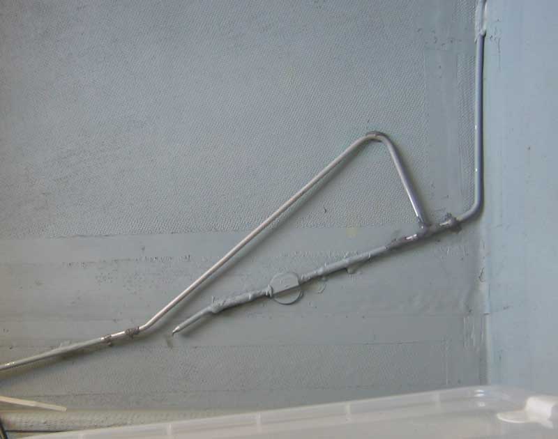
The picture shows the inside of the right-hand wall of the baggage compartment. The tubing is 3/16-inch aluminum; the joints are made by sliding a 1/4-inch o.d. sleeve over them and sealing with JB Weld. The static port is the round thing; it's about the size of a quarter.
After buying a new alternator for more than $600 a couple of weeks ago, today I found a spare alternator in my hangar -- in the box where I stored it 30 years ago.
[August 7, 2011]
In mid-July I had a visit from Francois Besse, the editor of the French magazine Piloter. We had a brief flight -- the intention was to go to Santa Paula for lunch, but we turned back when I saw that the alternator was not charging -- at the end of which he took this nice picture on short final at Whiteman.
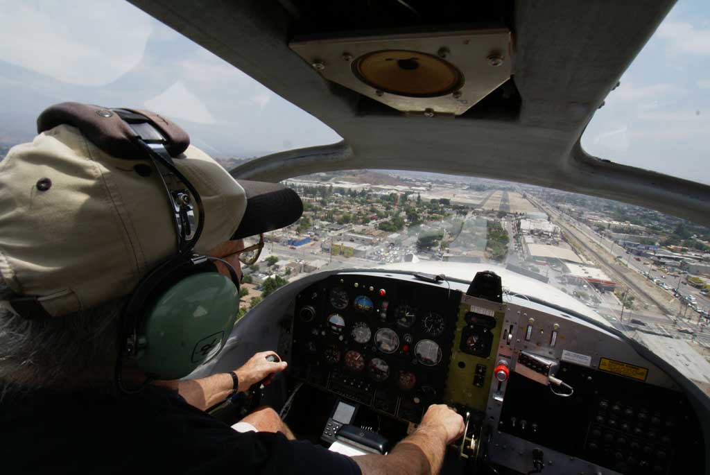
He complained about the reflection in the windshield of the gray area above the panel. I guess he has a point. The ceiling speaker has been derided as a quaint anachronism. Indeed, I have never used it.
[August 1, 2011]
I always feel some anxiety before leaving on a long trip, not because of the dangers of flying, but because I worry that something on the airplane will break in some godforsaken place and I will spend days in a state of intense impatience and boredom getting it fixed, while having to eat at restaurants that serve you too much meat and potatoes but no vegetables. Is this some new culinary fashion in the central United States, intended, perhaps, to hasten the general trend toward grotesque obesity? Worse, this dismal experience would cost a lot of money.
Luckily, none of that came to pass. The plane did fine, except for some flaky behavior on the part of my main gear struts, which don't seem to want to stay equally inflated. I really need to overhaul them -- not a difficult job: just disassemble, replace O-rings and reassemble. The engine used one quart of oil in 20 hours, and the oil mist on the windshield ceased toward the end of the trip, making me think that when it's comparatively heavy it's because the plane has been sitting and what's ending up on the windshield is the accumulated drips of several days. And the final version of the pilot's seat was comfortable for long flights. So that was all good.
Oddly, when we flew to Japan, Europe and Chile in the old Melmoth, I never worried about anything breaking. Youth!
There were some minor glitches. The halogen flashers are working fine, but I don't dare use them on the ground because they seem to overheat the lenses. The right nav light bulb burned out. The static source was briefly unreliable after heavy rain; I need to reroute the lines to eliminate a downhill segment immediately adjacent to the starboard port (though it seems amazing that any water at all can get into those tiny holes). I suspect that the air inlet that I added to the right lower cowling to cool the battery box -- it looks like a little machine gun port -- is actually behaving as an outlet, because the ram pressure in the cowling is higher than the pressure at the inlet face, which is down in the boundary layer. I intend to eliminate that inlet and take in battery cooling air directly from the lower plenum.
I am puzzled that while with the old voltage regulator the ammeter would indicate zero once the battery was recharged after startup, with the new one it seems to indicate around +5 amps all the time. The ammeter is wired to show charging current, not bus load, so this is unexpected. It could be that it is happening because the old regulator was set for 27 volts and this one is set for 28, and the Yuasa motorcycle batteries somehow prefer a slightly lower voltage. I struggled with this problem years ago and resolved it by adjusting the system voltage downward from 28 volts; I guess I just need to do the same again.
As was the case last year, I enjoyed tailwinds eastbound and part of the return trip, and when there were headwinds -- in Wisconsin and Iowa on Saturday -- they were mild. I had to work around some big thunderstorms near Las Vegas, New Mexico, but generally didn't need to deviate much from the GPS-coupled straight line. True airspeeds conformed closely to the Melmoth 2 Rule: 20 knots per gallon per hour. I generally cruised at around 8.5 gph and 170 ktas. Early in the trip I flew a long stretch at 15,500 and found that I could maintain good oxygen saturation -- around 93 or 94% -- with the Nelson meter just barely cracked, indicating well below 1 liter per minute.
[July 31, 2011]
The new alternator and regulator having been installed, I left for Oshkosh on the 26th, a day later than planned. I refueled in Salina, Kansas after a 6+15 flight, and continued to Prairie du Chien, at the confluence of the Wisconsin and Mississippi rivers, where I RON'd. I scud-ran in marginal 1,000-and-1 conditions into OSH the next morning. I left Saturday before noon, got fuel at Prairie du Chien (I was too impatient to wait for the OSH fuel truck, even though their gas was way cheaper, and the people at PDC were nice) and flew another 6+15 leg to Gallup, NM, where I slept. Airborne at the crack of dawn, I made it almost into LA before encountering, just west of Palmdale, rain so heavy that it took the paint off the leading edges of my empennage. About 20 hours for the round trip, and almost $1,200 worth of fuel. This can't go on much longer.
[July 22, 2011]
The full field test, which consisted of disconnecting the regulator and jumping the alternator output to the field post, so that the alternator simply bootstrapped without regulation, produced no charging voltage. I removed the alternator again -- now that I knew how to do it, it took only ten minutes and drew no blood -- and opened it up. I found much of the stator winding blackened from excessive heat.
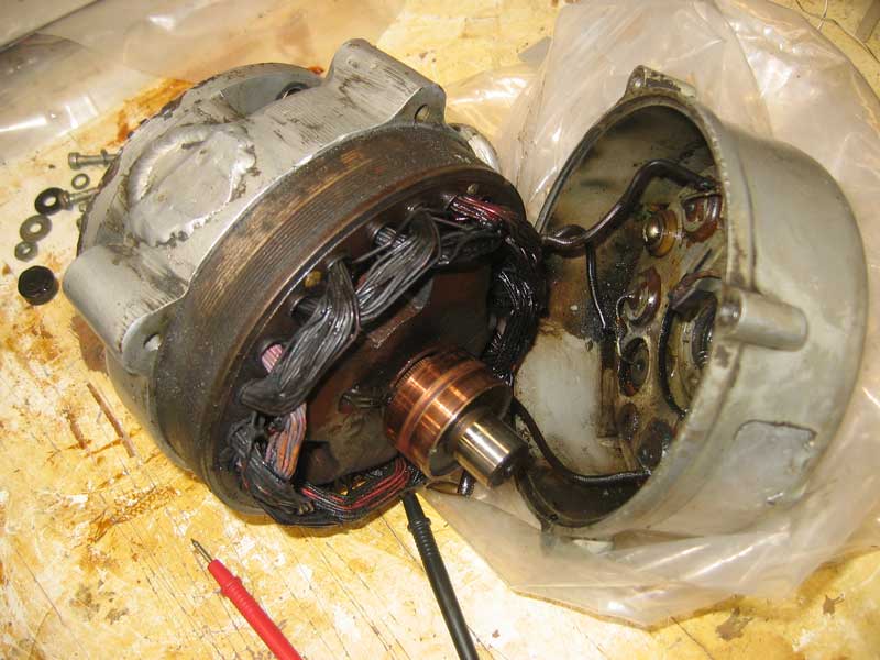
It is still not clear to me what exactly had failed, but the thing looked ugly enough that it seemed best to retire it and get a new one. It had, after all, lasted for about 1,500 hours of flying over a period of 34 years. What I think produced the heat damage was not the first thousand hours of its life in Melmoth 1. There it was cooled with a blast tube. In Melmoth 2, reasoning that it was now on the cold side of the baffles, I omitted any provision for active cooling. I should have provided it with a reverse blast tube -- that is, a vent to the low-pressure side of the baffles. The current version has a built-in fan; no blast tube is required to make air flow through it.
Mark, the foreman at Able Air, tried to locate a replacement, but the only one we could come up with was at Aero Accessories in Van Nuys, and the owner there had taken the day off and would not be back until Monday. My big worry now is that the new alternator will prove to be incompatible with the regulator I just bought. After that, I believe I will have run out of things to go wrong.
[July 21, 2011]
Quel mess. I installed the Cessna regulator -- this involved quite a lot of new wiring -- and then proceeded to damage it by stupidly attaching a ground lead to what I believed was a ground post, but was really A+. Melted some perfectly good wire. I thought I had damaged the alternator too, so I took it off -- a hideous job, even though there are only three bolts; they are in the most inaccessible locations imaginable -- and took it over to an aircraft accessory overhaul shop at Van Nuys. The guy put it on his testing machine and said it was OK, although the Woodruff key in the drive gear needed to be replaced. This he did, for a modest $20. I learned that my alternator, which I have had for around 35 years, is obsolete and no longer supported, so if it's dead I have to get a replacement. Since I do not have a core to trade for it, this could turn out to be pretty expensive.
I put the alternator back on the plane -- an even worse torment than taking it off, almost two hours, with considerable bloodshed -- and ordered a B&C regulator, which came this morning. Parenthetically, I love the amazing promptness with which stuff you order on line is delivered. This regulator had a completely different wiring hookup from either of the previous ones, plus a different mounting bolt pattern. I spent this afternoon hooking it up temporarily, only to see no charge. Tomorrow I have to do a "full field" test, which involves bypassing the regulator and letting the alternator self-regulate in response to changing rpm. There is a lot of advice on line about troubleshooting charging systems, and my system has so for been more or less within limits, except when it comes to actually putting out some voltage. Quite a puzzle.
[July 14, 2011]
On this moderately happy Bastille Day I found in one of the midden heaps in my hangar a Cessna voltage regulator.
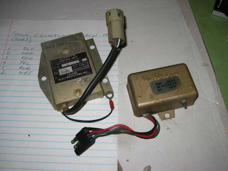
Its wires outnumber the ones on my present regulator by three, and I do not have the pinout for it, but a local FBO offered to let me look through his old maintenance manuals to figure it out. He said this unit contains an overvoltage relay, overvoltage warning light circuitry, etc., so that is what the other wires are about. Naturally it does not have the same footprint or attachment hole spacing as the old Motorola one, but I can work around that. Of course, for all I know it is burned out or soon will be. The Motorola lasted 38 years and 2,500 hours -- not bad for a cheap non-aircraft-quality part.
Russ Hardwick, with whom I had lunch today, brought me a couple of very bright LEDs, three or four of which, in series, would do nicely for panel lights, running on the 12-volt bus, which consists of the 1-amp output from an ancient Narco voltage reducer. At present I think the only load on it is the GPS. Russ seemed to think that if I wanted more 12-volt current I could tap 12 volts off the middle of my pair of batteries; he suspected that batteries work on Communist principles: from each according to his ability, to each according to his need. That might work for batteries; it certainly wouldn't for people. At any rate, the LEDs draw almost no current, so I think the Narco will handle them fine.
[July 13, 2011]
Took off for Santa Paula with Francois Besse, the visiting editor of a French aviation magazine. We hadn't gotten very far when I noticed that the alternator was not charging, and we turned back. After some troubleshooting I concluded that the voltage regulator had failed. It is a little Motorola unit that I believe was used on some trucks that have 24-volt electrical systems. I must have gotten it almost 40 years ago. Online I found physically similar ones on offer from a Chinese firm, but only if I wanted to buy 500 or more. It looks as if I may have to get a different regulator and rig up a new mount for it. Spruce has a couple that incorporate overvoltage protection, something neither Melmoth has ever had.
[July 12, 2011]
The countdown to departure for Oshkosh has begun. Or, to put it a little less portentously, I started doing a lot of deferred maintenance. I installed the small SkyTec starter, which is not that small, or light, any more, but which will clear the intake manifold when I turn the latter around. I greased the landing gear retraction joints. I found and fixed a loose Cannon plug on the oil temperature sensor; it was probably responsible for the fluctuating oil temperatures I've been seeing lately. (Fluctuating oil pressure can be a dire symptom, but fluctuating temperature is almost certainly an instrumentation problem.) I continued my still unsuccessful search for the source of a pretty sizeable hydraulic fluid leak at the right outboard actuator. I replenished the hydraulic fluid reservoir, which was significantly depleted after just ten hours of flying. There are still leaks in several places. I cleaned the windshield, which had more oil spray than usual on it, and carefully inspected the engine without finding any new oil leaks. The oil on the windshield is a nuisance, but it is actually not very much oil, since the engine is still going 15 hours or so on a quart. I now need to put the plane on jacks, swing the gear, make sure all the doors are closing properly, and regrease the wheel bearings. It's pretty clear that I won't have the remote control for the oxygen bottle valve, or the remote oxygen pressure indicator, installed before I go, because I have other things to do than work on the plane. But at least I will have oxygen.
[July 2, 2011]
A correspondent, Ryan Niederkohr, explained the apparent inconsistencies in the results of my oxygen experiments of last week. Oxygen can be dissolved in blood without being bound to hemoglobin. The "oxygen saturation" measured by the fingertip oximeter is the amount of bound oxygen in the blood; obviously, once 100% of hemoglobin molecules are carrying their baggage of oxygen, there's no room for more. But there can be extra free oxygen just floating around in the blood if you have been breathing an oxygen-rich mixture, and as hemoglobin discharges its cargo more oxygen is present to bond to it. Therefore the decline in saturation percentage does not necessarily keep pace with change in altitude or in liters-per-minute delivered from the oxygen bottle. As Niederkohr explained, I would have seen more linear results if I had started from a minimum oxygen flow rate and worked upward.
Because my planned re-orientation of the intake manifold was going to encounter interference from the full-size starter motor that is currently on the engine, I got over my annoyance with Sky-Tec and returned my old small starter, together with a gift of $250, in exchange for a new small starter. I requested the same model, but somebody called me up from the factory and strongly suggested that I get the -5 rather than the -3 model, because that is what they recommend for the "larger" Continental engines. I think of my 360 cu. in. engine as one of the smaller Continentals, or at most as a medium-sized one, but I went for the -5 even though it weighs three pounds more than the -3. One advantage it has -- I think -- is that the -5 has a solenoid-operated electric clutch; the -3 has a centrifugal clutch. Now, the engine itself has a starter clutch consisting of a coil string that tightens around a shaft when torqued by the starter. In theory -- this must have been the theory that led the Sky-Tec people to design the original starter without a freewheeling mechanism -- the coil spring would completely disengage the engine from the starter, which did not want to rotate at all when it was not energized. But it turned out that the spring clutch would drag slightly, and tighten, and drag some more, until the whole assembly wore out and had to be replaced at a cost of over $800. For some reason I feel as if the solenoid clutch is more likely to resolve this problem completely than a centrifugal clutch is.
[June 24, 2011]
The oxygen system worked, but I can't make much sense of the pulse oximeter readings. I climbed to 12,500 feet and checked saturation; it was 83-86 (it tends to jump around a bit) and pulse was 106. (My resting pulse is usually around 60-65, but when oxygen is in short supply your pulse goes up.) I then put on the oxygen mask (which seems to be as good as new despite being more than 30 years old, but I haven't checked the built-in mic yet) and set 1.5 liters per minute on the flowmeter. Saturation percentage (hereinafter Sp) immediately went to 98 and pulse to 99. I kept reducing the flow rate with the following results (the first item is flow rate in liters per minute, the second Sp, the third pulse rate):
1.25:
98-99 / 90-92
1.00: 98 / 88-92
0.75: 96 / 90
So far so good. But this is where it gets weird. The flowmeter actually isn't marked below 1.0, but I thought I could extrapolate where 0.75 probably is. If I kept turning the knob the little ball became still. So maybe that's zero. But zero is about as far below 1.0 as 1.5 is above it, so maybe the thing is nonlinear at low flow rates, and that's probably why it isn't marked below 1.0.
With the knob screwed in all the way and the ball dead, I get 92-93 / 92-93. Then I disconnect the mask from the oxygen supply, and it goes to 90-91 / 91-94. So it looks as if oxygen remains bound to the blood for some time, because this is the same amount of oxygen as gave 83-86 / 106 before. Finally I connected the mask again and just cracked the valve, so that the ball gave a tiny movement: now I got 92-93 / 93.
I tentatively concluded that it's possible that the valve on the flowmeter doesn't close entirely. It would be interesting to know, if this is the case, what the flow rate is when the valve is ostensibly closed. Anyway, all this is of somewhat academic interest, since the value would be different higher up and in any case I would be adjusting the flow to get an Sp of 90 or so, which corresponds to about 9,000 feet without oxygen. I think I will repeat the whole experiment, but rather than start with 1.5 lpm and work down, I'll start with the valve closed and work upward; that will eliminate any lag effect, and will also make clear whether there is any difference between no oxygen at all and a closed valve on the flowmeter. I will also go to a higher altitude.
The flight, which was to Paso Robles, about 140 nm, took 1.1 hours up and an hour back, and used a total of 16.4 gallons of fuel.
Today I found that the battery water was down, just on the battery closer to the positive pole; so, as planned, I swapped the position of the batteries to see whether the excessive evaporation is due to the battery itself or to the battery tender that I use on the ground.
[June 22, 2011]
The oxygen bottle is now locked down and connected in a half-baked way to the regulator and outlets. I'm making a round trip of a few hundred miles tomorrow; I'm curious to see how my blood oxygen saturation responds to various rates of oxygen flow. Also whether the microphone in my oxygen mask still works after all these years. I probably last used that mask in 1982.
[June 14, 2011]
There is something about the arrival of summer that slows me to a crawl. The first heat is enervating; later I get used to it, and am probably less bothered by August and September than a lot of other people are. At any rate, I have accomplished almost nothing in the past three weeks, even though, after a few hot days, the weather had actually turned rather chilly and I was discouraged from going to the annual barbecue at Antique Aero in Paso Robles by rain, of all things. Not quite nothing, however. I have replaced the knob on the oxygen bottle valve with a lever and spring arrangement that will allow me to open it by pulling on a cord. It will require some sort of hook to hold the cord against the spring while the bottle is in use; when the cord is released, the spring closes the bottle. It seems to work satisfactorily on the bench, at least. I still have to figure out how I'm going to hold the ox bottle in place, but that shouldn't be difficult; there's a natural cradle for it under the rear seat footrest.
[May 25, 2011]
Further study of the problem of reversing the intake manifold has led me to think that it can be done after all by sawing up the existing manifold and ducting and welding it back together differently. The throttle body would end up right above the vacuum pump, which is okay, and the manifold would clear the oil filler neck on the left side of the engine. On the right side the old starter motor still creates a slight interference; I guess I will have to bend over and pay SkyTec for a new small starter that does not suffer from the same design fault as the one I currently have lying on the floor, where I wish I had left it when I first got it.
As for the matter of opening and closing the needle valve on the oxygen bottle by remote control, several suggestions have been offered, of which the most useful was to use an automotive speedometer cable with a small jackscrew. Jackscrews sound complicated, but are actually very easy to make with a bit of threaded rod or a sawn-off bolt. In the meantime my thinking had drifted to the minimalist solution of a piece of cord pulling the valve open and a spring pulling it shut. The current handle on the valve would of course be replaced with an arm a couple of inches long to provide some leverage and length of travel. As I mentioned a few days ago, the valve does not need to turn many times; somewhere between 45 and 90 degrees of rotation would be sufficient.
Since I have been thinking quite a bit about cooling issues, I got out my charts of delta p vs cooling air mass flow -- this is an item that manufacturers provide to OEMs -- and did a curve fit to the data. For what it's worth, the cooling air flow for my engine, in pounds per second, is 1.031 times the 0.541 power of delta p, the pressure drop across the engine expressed in inches of water. For cubic feet per second, replace 1.031 with 12.13 and divide by the density ratio. This is just part of what you need to know about cooling, unfortunately; other curves, which I have not yet modeled, relate delta p to power setting, ambient temperature, and cylinder head temperature. Ultimately, these calculations drive the size of inlets and outlets. I think, however, that inlet size, in particular, receives too much attention. People are very proud of having teeny-weeny round inlets. But you can't cram more air into an inlet than can find a way to get out. It is outlet size that controls the total mass flow, along with the impedance of the engine itself. Air finds its way around an oversized inlet, provided that it is well shaped, without a lot of trouble.
[May 20, 2011]
Since I am not one of those who believe that time ends tomorrow and am not a candidate for rapture in any case, I have been thinking about various things to do next. A couple of tasks remain unfinished: the oxygen system is hanging fire until I decide how I am going to open and shut the needle valve on the bottle, and I still need to install panel lights to complete the provisions for night flying. Actually, most people would consider night flying equipment to be incomplete until a landing light is added, so I guess I'm still far off. I don't fly at night any more, however, so none of this seems very urgent.
On the other hand, I do fly at high altitudes, and so the oxygen seems more useful. Yesterday Russ Hardwick and I discussed how to open and close the oxygen bottle by remote control. I was thinking about a torque tube; he suggested solenoids. A few minutes later he retracted the solenoid suggestion because it would shut the needle valve too violently and eventually damage it. I'm not sure that objection could not be dealt with by inserting a spring between the solenoid and the valve handle. He thought it would be best to use something that gave feedback, and proposed a hydraulic circuit; I made a counteroffer of a cable loop, but then raised him with a worm gear and sector driven by a small electric motor. It too would require some sort of spring or other cushion to avoid damaging the needle valve. Obviously, the options are impractically many. One of the desiderata is ease of removing the bottle; this is what inclined me to some sort of electrical solution. In any case I am indebted to Russ for pointing out that it is not necessary to turn the needle valve very far to provide the needed flow of oxygen. 45 degrees is plenty.
While I was mulling over all these choices, I also began thinking again about reversing the intake manifold in order to put the throttle body behind the engine, in the cool air side of the cowling, and to eliminate the transverse 2-inch tubes that currently impede air flowing out of the cooling air outlets. Today I uncowled the engine and studied the various interferences that I would encounter. I came to the conclusion that it would not be possible to simply make two saw cuts, flip something over, and come out with a workable reversed manifold. The oil filler neck gets in the way on one side and the starter motor mounting on the other. The oil filter, in its new position high on the firewall, is also a problem, and complicates running a pipe from the turbocharger to the throttle body. It appears that the best way to solve all of the problems will be to mount the throttle body wherever I want it to be, and then to bend and weld tubing as needed to connect it to the manifold and the turbocharger.
[May 9, 2011]
On Saturday I flew up to Pine Mountain Lake (Groveland), which is in the Sierra foothills on roughly the latitude of San Francisco, to present a little slide show about Melmoth 1 to the pilots' association there. My host overnight was Wayne Handley, a remarkable acrobatic pilot who is currently the president of the association. Wayne took me over to see Clay Lacy, whom I knew years ago at Van Nuys, having gotten my Learjet rating at his place. This turned out to be quite a stroll down memory lane. When we found him he was driving a 1955 Chevy Bel Air, turquoise and white, identical to my mother's car when I was an early teen. Clay's has 28,000 original miles, and looks it. In his hangar -- everybody there seemed to have a hangar -- was a Linn Midget Mustang that had belonged to the father of Clay's lady friend. That was an airplane that had impressed me quite a bit when I first saw it in Jane's in 1962, but I had never seen one in real life. Powered by a 125-hp converted GPU, it was quite fast, but I don't know how it managed to land; its tailwheel is about two inches in diameter, and its reported landing speed was 80 mph. That works out to over 13,000 rpm. Span is 16 feet. Not a lot of room inside for folding and unfolding WAC charts, or even arms.
The next morning the clouds were almost on the deck; I filed IFR back down to LA, flew the ILS at Van Nuys and broke off under the overcast to go to Whiteman. The makeshift GPS/VOR tracking system worked nicely, slaving to the old Lowrance GPS, either VOR or the ILS, or holding heading, as needed. You can do a lot with a wing leveler and one of these things.
Performance for the trip continued to be 170 ktas at 8.5 gph, which implies an F of 2.35 rather than the 2.25 I calculated a while ago. Ravages of time.
Today I was buying some more hydraulic fluid -- I still leak quite a bit of it -- when the radio shop guy walked by. I asked him about the PTT switch problem, and he suggested that it might be low voltage failing to operate a relay in the radio -- old radios, like my Collins MicroLine ones, had relays in the PTT circuit. That makes perfect sense. Next time, he said, try raising the rpm a little.
[May 4, 2011]
I had lunch at Camarillo with Javier Arango to discuss his collection of World War One airplanes, about which I am doing an article for Air & Space magazine. On starting up, I found that the press-to-talk switch on the radio would not work. This has happened a couple of times before, always after startup, and always it has resolved itself spontaneously after some time passed. This time I had to call the tower by cell phone to get a takeoff clearance. That worked fine, but when I was departing downwind the controller asked me to squawk NORDO. I reached over to select 7600 and then I suddenly thought, "Wait, is that hijack?" I couldn't remember, and not wishing to trigger a security emergency I dug around in my flight bag for one of those everything-you-need-to-know books. It turned out that NORDO is 7600; hijack is 7500. Anyway, I landed NORDO at Whiteman, taxied back to the hangar, turned off the plane, then turned on the master again and clicked the press-to-talk switch. It worked.
I sent the ox regulator to C&L Aero and have been making tooling for some fiberglass parts, including a fitted funnel for draining the oil. We had a visitor for a few days and I was going to museums and stuff rather than working on the plane; so I haven't gotten much done..
[April 22, 2011]
Further inspection revealed that the problem is simply that the relief valve on the oxygen pressure regulator is missing; broken off, in fact. If I put my thumb over the hole, the oxygen flows normally to the mask. Stumbling aimlessly around the Web with search strings that I never seem able to recreate later, I found C&L Aero in Redding, in Northern California, who charge $90 to overhaul an Alar A2000 -- though they admit that there are no life-limited parts in it, and so overhauling normally means just taking it apart, putting it back together, and, I suppose, maybe hitting it with a fresh coat of black paint. A replacement relief valve -- the originals are no longer to be found -- is another $45. On Monday I'll go by Norton Sales in North Hollywood, world center of aerospace equipment unobtainable elsewhere, to see whether they can do any better, but failing that C&L seems like a pretty good deal.
Yesterday was my granddaughter's birthday. My daughter (her aunt) gave her two tutus. She turned two, so there has to be a tongue-twister in there somewhere.
[April 20, 2011]
After correcting yesterday's errors I connected my welding oxygen bottle to the regulator and the outlets. Concerned that the decades-old armored high-pressure hose might burst and whip around murderously, I put a big piece of carpet on top of it and a packed parachute on top of that. I then just cracked the valve on the bottle. It gave forth a hissing sound that did not immediately diminish, so I gather something is leaking. Most likely the regulator is frozen after all these years. I'll test this more systematically tomorrow; I had a two-year-old sleeping in the car and she woke up just as I was starting. I looked around online for who might overhaul the regulator if it needs overhauling; one company promised a price of "under $600" -- which I suppose means $599.99 before tax -- for almost any regulator. That certainly seems generous -- to themselves.
My bottle, by the way, is a 680-liter (24 cu ft) aluminum one. It ought in principle to be sufficient for 20 hours at 18,000 ft for one person, assuming the most efficient delivery rate, which I gather from this excellent report is around 0.5 liter/minute. Less optimistically, ten hours or so. The report says that the valve on the bottle should not be opened until the oxygen is to be used; otherwise the bottle will leak down through a constant-flow regulator. So much for my idea of opening the bottle valve during the preflight.
[April 19, 2011]
A couple of people had suggestions about why the oxygen fittings are steel. One was fire resistance. That makes sense, but ought to apply to fuel as well as oxygen, and fuel lines are aluminum. Another suggestion was dissimilar metals corrosion, but since the body of the regulator is aluminum, not steel, that would not seem to be an issue. Oxygen is stored in aluminum, steel or composite bottles, and the valves on the bottles are generally either brass or steel. At any rate, there are just a few fittings, so I guess I'll stick with the steel. I installed the two outlets in the floor today, but I didn't get them quite right, and I'll have to redo the installation tomorrow. I also want to hook the whole system together outside the airplane to make sure it working before I install it. Baby steps.
[April 14, 2011]
Further study of the oxygen installation today. My regulator, an Alar A2000, was last overhauled in 1979. I'll try it and see how it performs. I rethought the question of whether or not to have a gauge, and decided that it would not be much trouble to install one alongside the two oxygen outlets. As for turning the bottle on and off, I think maybe I can make the valve accessible through a small hole in the back seat footrest. I'm curious why all the fittings associated with the regulator are steel; for small-diameter tubing, aluminum fittings would be amply strong. Rummaging through my junk collection I found that I have a lifetime supply of nasal cannulas; what hospital I robbed to get them, I can't recall. I need to read up on cannulas vs masks. I don't understand how flowing oxygen out of the cannula continuously, whether you're inhaling or exhaling, can be very efficient. Perhaps the flow is retarded by exhalation. I located a second ignition harness, which I assume must belong to the Slick mags. Still haven't found out the cost of the pressurization kit for the Bendixes, if in fact it even exists.
[April 13, 2011]
I have been closing in on installing the long-delayed oxygen system. It's pretty simple: a tank, a constant-flow regulator, two outlets, and a filling port in the sill of the baggage door. I am not currently planning to have a pressure gauge that is visible to the pilot; the idea would be to check the pressure gauge on the bottle before takeoff or know the pressure from a previous flight, and to know how much time a given pressure represents. So far I have just been figuring out how to arrange the various components so that they require a minimum of modification.
In addition to the oxygen system itself, I have to deal with the magneto pressurization question. Mags need to be pressurized to prevent cross-sparking at high altitude. Melmoth 2 started life with pressurized Slick mags, but after one of them failed in 2003 (a bad coil) I replaced them with the factory-supplied Bendixes that I had put into storage back when I first turbocharged Melmoth 1. Since then I have seldom flown above 15,500 feet. I recently learned that a pressurization kit is available for the Bendixes, which are generally thought to be of superior quality; I'm undecided about whether to invest in pressurizing the Bendixes or to just return to the Slicks, having replaced the bad coil a number of years ago.
[April 3, 2011]
I had a request from a French blogger, Xavier Cotton, for some observations about Melmoth's flying qualities. Cotton, who is a private pilot and an air traffic controller and obviously passioné des avions (crazy about airplanes), has a very nice site featuring pictures and descriptions of lots of interesting planes. If you don't understand French Google will provide a surprisingly readable translation, and the pictures are worth a visit.
When I began writing something for Cotton I realized, first, that I have never given much of a description of Melmoth 2's flying qualities here, and second, that it is difficult for me to do so, in part because I take them for granted and in part because they are -- I believe -- not particularly unusual. Nevertheless, here goes -- though this is less about qualities than procedures.
Taxiing is conventional, using nosewheel steering; if the CG is far aft, however, the nose strut extends fully, nosewheel steering disappears, and I am reduced to steering with brakes. This is very easy, fortunately.
I usually use 34/2,800 for takeoff, but I have up to 41 inches available. (The engine is rated at 200 hp at at 41/2,575; it probably puts out 230 hp or so at 41/2,800.) Acceleration is rapid (about .25 G) and I rotate at around 70 kias. I retract the gear, climb initially at 85 kias, and reduce power to 30/2500. After flap retraction, which takes a while because the flap has such a long way to go, the speed automatically settles at 95 kias. I reduce power further to 27/2300 am at 1000 agl by the time I turn from crosswind to downwind; I normally use the downwind departure at Whiteman because of Burbank Class C.
Once cleaned up, I lean the mixture to 50 degrees lean of peak and trim for a cruise-climb at about 110 kias and 8.5 gph (this does not make much sense; I should climb at a higher power setting, but still lean of peak). Rate of climb at this setting is 500 fpm when I'm alone in the airplane. I set the cowl flaps as required to hold the CHTs below 200 C. I tend to cruise high, climbing to 11,500 or 12,500 for any trip of an hour or more. A typical cruise power setting is 27/2,300, or about 55%, which gives 8.4-8.8 gph and 135-140 kias for a true speed around 170-175 ktas. On a standard day, the cowl flaps are fully closed. Handling is straightforward, with little adverse yaw and somewhat heavier roll forces than you would expect from such narrow ailerons; but the sidestick is very short. Roll-yaw coupling is satisfactory, and the airplane can be steered with rudder alone in smooth air without the ball getting very far out of center. Hands-off stability in smooth air is good; in turbulence, however, the high roll forces are fatiguing.
I usually cruise with the autopilot coupled to the GPS; it can also be coupled to either VOR. Ventilation is good, and I have never felt uncomfortably hot despite the bubble canopy. When roll trim is neutral, usually quite soon after takeoff, I turn on automatic fuel tank switching. The two fuel tanks switch automatically every seven minutes. In such an automated environment, the main challenge is to stay alert.
I usually begin my descent quite far out, reducing power to 20/1900 and descending at 500 to 800 fpm. Around three miles out, I turn off the fuel tank switcher, open the cowl flaps (in case it is necessary to go around) and deploy the airbrake (if it is not already out). At 100 kias or below I lower the landing gear and set 10 degrees of flap. The airbrake produces a nose-up trim change that more or less cancels the flap's nose-down one. Approach speed is around 75 kias, but I rely on the angle of attack indicator rather than the airspeed indicator for approach attitude guidance. On half-mile final I set full flap. I carry about 17-18 in Hg on final. I reduce power and begin to flare fairly high to bleed off speed, because the airplane likes to float. In ground effect I hold it off for as long as I can; the nose gets quite high, with the stall warning bleating during the final seconds before the wheels touch at around 50-55 kias. Stick forces are light during the flare and landing. When the mains touch I pull the stick all the way back to hold the nosewheel off -- with variable success. Once the nosewheel is down I brake firmly; the 3/8-inch thick brake pads provide good energy absorption and deceleration is quite strong. The airplane stops in a few hundred feet.
So that's about it; basically, except for its range of 3,000 miles, it seems like a normal airplane.
[March 23, 2011]
I climbed to 13,500 with the oximeter, which reports "saturation" -- the percentage of the potential oxygen capacity of blood that it is actually carrying -- and pulse rate. My resting pulse is usually in the 60s, but it was a steady 85 while flying. The saturation began at 99%, dropped to 98% at 7,000 feet, 94 at 10,000, and finally 86 at 13,500. There was some fluctuation, and saturation seemed to lag behind altitude by a minute or two, since the readings were different on the way down: 94% at 6,500, 96% on final approach, and 98% as I rolled up to my hangar.
At 13,500 I tried squaring some two-digit numbers in my head, and although I felt that I was doing it as rapidly as normally, I wrote down the answers and after landing found two out of three to be wrong. Furthermore, they were wrong in ways that were immediately obvious to me on the ground. For example, for 84^2 I wrote down 9,056. Now, it is self-evident that since 80^2 is 6,400 and 90^2 is 8,100, 84^2 cannot be 9,056. (It is in fact 7,056.) I'm not sure where the 9 came from; maybe I wrote it down incorrectly after solving correctly. But in any case, I missed the obvious mistake, and this probably had to do with my oxygen saturation being 86%. Whether this has any bearing at all on being able to cruise an airplane, I don't know. Cross-country flying on autopilot is mainly a matter of remaining awake. On the other hand, coping with an emergency is a hit-or-miss business; I have not always made good decisions in emergencies even at low altitude.
Here is a page, copied -- I hope this qualifies as "fair use" -- from a textbook found online, containing a chart of saturation against altitude (the latter being defined in terms of the oxygen partial pressure, which is 21% of the atmospheric pressure). I am a 67-year-old nonsmoker; it is not clear why the values given here are so different from the ones I recorded. Perhaps the oximeter is not reliable.
One noteworthy thing about this chart is the fact that the rate of loss of saturation with altitude increases rapidly above 12,000 feet or so.
On another topic, I checked the wingtip light flasher for radio noise. There was none.
[March 21, 2011]
For more than a week I've been helping my son help his wife prepare a yoga studio for its grand opening, which took place this last weekend. No time for the plane at all. But I finally got back out there today. The nav lights and flashers are now working, so that rather basic requirement is taken care of. I still need to rig up panel lights, however.
After writing about some hypoxia-related accidents for my June Aftermath column and then discovering that pulse oximeters have become very cheap. I bought one ($38). I intend to climb tomorrow -- between rainstorms -- to some goodly height and record my oxygen saturation. I have always believed that I can cruise for quite a while at 15,500 feet without supplemental oxygen and not experience any significant indications of hypoxia. To test myself, I would periodically square two-digit numbers mentally and assess how difficult I found the task and how long it took me. (This is a simple procedure, using the a^2 + 2ab (or -2ab) + b^2 template from high school algebra; it's just a matter of remembering the results of a couple of operations and adding them.) I am of course perfectly aware that a hypoxic person is not the best judge of his own mental capacities; but I am also aware that people react to altitude in quite different ways, and so I am curious to see an objective, numerical measure of my blood oxygen saturation and to compare it with some "normal" values, if I can find them. I have done a couple of pressure chamber rides, of course, but they are not really very informative, because their whole purpose is to hit you with a dramatic demonstration of oxygen deprivation; they never just take you to 14,000, say, and keep you there for two hours so that you can develop a more refined sense of what relatively mild hypoxia actually feels like.
I donate platelets at a local hospital every two weeks, and I asked one of the phlebotomists how, or whether, one's proneness to hypoxia would be affected by donating a pint of whole blood. She passed the question on to a doctor, who said that he didn't think so; but I doubt he had any special knowledge. I'll call FAA Aeromedical and see if I can find out something more than is contained in every magazine article about hypoxia written since the dawn of aviation.
[March 2, 2011]
Between wiring, bad weather and general distractions, I had not flown since returning from Santa Fe at the end of January; so this afternoon I cruised around the outskirts of the San Fernando Valley, down to Malibu, and back over the Sepulveda Pass and alongside Van Nuys. I found on approach to Whiteman that increasing the pitch trim tab travel from 20 to 25 degrees ANU did make it possible to trim hands-off to approach speed with takeoff, but not full, flap and the most forward CG position. Since I fly most of the approach with takeoff flap -- fully shifted aft to the trailing edge of the wing, but deflected only 10 degrees -- and go to the full 30-degree deflection only on a half mile final or so, this is adequate. When there are two or more people in the plane, or any baggage to speak of, I think I will be able to trim to approach speed, or quite close to it, even with full flap.
A correspondent, Frank Shoemaker, suggested checking the voltages of the two batteries after landing. I did so, and found the one closer to the negative pole to be at 12.9 to 13.0 volts and the other to be at 12.8 to 12.9. The next time I add water I will swap the positions of the batteries in order to see whether the difference is due to the batteries themselves or to their positions in the charging circuit. I will also check the voltages when the batteries have just been removed from their respective tenders to see whether they top off to different levels.
[February 25, 2011]
A couple of people suggested swapping the positions of the batteries to see whether the difference in water consumption moves with the battery. I will do that; but if the difference stays put, it will remain uncertain whether the reason is the physical position of the battery, its position in the electrical circuit, or the associated tender.
I posted another YouTube video, this one shot during a flight from Whiteman to Santa Paula. It's not very good, but, like Everest, it's there.
[February 24, 2011]
I've been stringing wires here and there, hooking up the nav lights, pitot heat, and flashers. I also happened to check the battery fluid level and found that it needed some water. But, as is always the case, one of the two batteries -- I use two 14-volt Yuasa motorcycle batteries in series to supply a 28-volt electrical system -- required much more water than the other. It is always the one closer to the negative pole. My first thought was that this had something to do with the battery tender, which keeps the batteries at top charge; but I use two of these "smart chargers," one for each battery, and so they should not behave differently. The battery that needs more water is farther from the exhaust pipe and other sources of radiated heat, and the batteries are in an insulated box anyway, so I don't suppose the difference has to do with temperature, unless from internal causes. Does anyone reading these bottle-messages know whether there is something about the order of the batteries in the circuit that would affect the evaporation of battery fluid, or whether this is simply a matter of two batteries having slightly different personalities?
For a long time I have been putting off installing the oxygen system that was always planned and that seems like a logical requirement for a turbocharged airplane. The problem with it is that it's added weight and would get used very seldom. Once in a while you can get extra speed high up, but it's costly, since although at home you can load your system with non-aviation oxygen at minimal cost, when you're away an oxygen charge is quite expensive -- probably more than an occasional 220-knot groundspeed is worth. My present inclination is to install the plumbing, which entails a comparatively small weight penalty, and leave the bottle behind unless I really think I'm going to use it. But of course what really happens is that you get lazy and just leave it in there.
[February 11, 2011]
I was afraid that upholstering the seat would change the feel of the cushions, and it did; the cover itself tends to compress things here and there, especially around the edges. The seat pan now felt too short, so I remade the metal brackets that hinge the back to the pan -- three times, in fact, since I kept making mistakes or changing my mind about what should be where -- and now it feels pretty comfortable. I won't know for certain until I make another 4-hour flight. I also removed, cleaned, and dry-lubed (with a graphite-moly disulphide spray that a reader recommended) the pins that hold the windows shut. I'm wondering, however, whether frozen grease was really what made them so stiff on my last trip, or whether it's actually the shrinking acrylic windows pulling the window frames out of shape.
Next project is to shim the gutters around the windows and hit them with a heat gun to temporarily soften the epoxy and, I hope, increase the clearance so that the windows are not so hard to open at low temperatures (this is a different problem from the difficulty with the locking pins).
[February 3, 2011]
I did the trim cable modification that I was thinking about a couple of weeks ago. It turned out to be more complicated than I anticipated -- what doesn't? -- and netted only a five-degree gain in aircraft nose-up trim tab deflection, from 20 degrees to 25. I picked up 10 degrees of additional travel in the nose-down direction, but that's pretty useless. I also put in a positive stop for the cable, so that the end of its range will no longer be signaled by the swaged cable end trying to wrap itself around a pulley. I have not yet flown to see whether the added tab travel has any effect on the minimum speed to which I can trim with a forward CG. What ultimately limited the tab's travel was not the cable or chain but clearances among the trim components, which are pretty tightly packed up in the T-tail intersection.
I also re-centered the out-of-whack flap valve and safetied the flap cable to the sector in the flap handle on the panel, so that it can't slip off the next time I fly into a deep freeze. Also, having flown many hours in my makeshift seat -- I can't even remember when I last adjusted the shape of the foam padding -- I took it to an upholstery shop in Highland Park to make it official. It's supposed to be done tomorrow. Who knows -- one of these days I may finish painting the instrument panel.
[January 30, 2011]
Most flights are entirely uneventful. A few are all too eventful.
I went to Santa Fe on Monday, January 24, to fly an airplane called the Sunbird Seeker at Albuquerque. After cruising at 13,500 where the OAT was -16 C, I descended into Santa Fe to find that when I selected flaps down the cable that connects the handle on the panel to the valve under the seat jumped its groove. Okay; I landed with no flap. The cable loop was surprisingly slack, and I concluded that the entire airplane had shrunk because of the cold. Since epoxy shrinks much more than steel, and for that matter the steel cable was within the warm cockpit, the effect had been to loosen the cable. I made a note to safety-wire the cable to the sector rather than rely on tension to hold it in place. Other temperature-related observations were that the window gutters interfere with the frames when cold and make the windows very hard to open, and that the window locking pins need to be thoroughly cleaned and dry-lubed. My well-intentioned greasing of them was fine for Southern California, but not such a great idea for a Rocky Mountain winter.
I felt some odd vibrations during that four-hour flight, and when I took off on Wednesday to return home I thought the engine did not feel right. I turned back to Santa Fe, where a mechanic named Kermit at Aero Services found my right mag to be 5 degrees more advanced than the left and my fine wire plugs, veterans of many happy hours in both Melmoth 1 and Melmoth 2, to be worn out. He rebuilt both mags (but did not replace any parts) and installed nine new massive-electrode plugs -- all they had in stock of the appropriate type -- along with the three least heinous of my old ones. I then started west, found the engine restored to smoothness, and got to Winslow as night was falling. I spent the night there.
In the morning the temperature was 14 degrees F. and the airplane was thoroughly cold-soaked. It took me a long time to get the engine to start; when it finally caught, I was using the flooded-engine technique -- mixture leaned, throttle wide open -- which often has the effect of letting the engine race briefly while you're getting the mixture forward and the throttle back. When I ran it up, I found the right mag seemingly completely dead and the left mag showing no drop -- as would be expected if the right mag were not supplying any spark. There was no mechanic at Winslow, but the FBO, Wiseman Aviation, also has a Flagstaff base, and they put me on the phone with the mechanic there. He said to disconnect the P lead from the right mag, since evidently something was grounding the mag. This was sensible advice, but it did not work out especially well.
I took off and found the engine still quite rough, so I went to Flagstaff, just 20 minutes away, and presented myself to the mechanic with whom I had spoken. His name was Rory Goforth -- a poetic name, I thought, for someone who sends airplanes roaring out into the world. I described the problem, including the fact that both mags had just been rebuilt. I should have kept my mouth shut. My explanation had the effect of convincing both him and me that the problem, whatever it was, could not be in the mags. In retrospect, this seems puzzling to me; after all, I had just found the right mag to be not working. But I had persuaded myself that this was due to the P lead, not the mag itself. Rory spent a couple of hours going over the usual suspects -- injectors, ignition harness, plugs -- without finding anything amiss. I took off again, flew ten miles, still didn't like the feel of it, and returned to Flagstaff.
At some point I suggested that I run up the engine and he listen to it. This wasn't especially brilliant -- it was the only thing left to do -- but it turned out to be what we should have done in the first place. As I turned off the left mag, the engine died on cue. But Rory heard something I hadn't heard -- a single pop; and he understood that it meant that the mag was not dead after all -- just malfunctioning badly. I tried the mag check again, this time letting the engine spool down for a longer time, and sure enough there was a series of pops. The right mag was firing on just one cylinder. This seemed mysterious until we looked -- at last! -- into the port at the nylon timing gear. I turned the prop. The gear did not turn. Eureka!
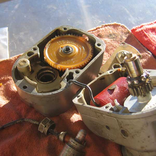
What apparently had happened was that the nylon gear, embrittled by age and cold, had shed a mess of teeth when the engine suddenly roared to life at Winslow. The replacement gear arrived the next morning and I returned to LA that afternoon. It was a smooth, windless and vibration-free flight.
A couple of days after returning, I was making circuits at Santa Paula for pictures to accompany a Technicalities column when I noticed that any time I operated the hydraulic pump the flaps moved upward slowly. What had happened was that the center-off positions of the panel handle and the valve had gotten misaligned when I tightened the flap cable loop at Santa Fe, so that when the handle was in the "off" position the valve was actually slightly open in the "down" direction. When tensioning the cable loop one has to adjust both legs, not just one. I had encountered that issue before; but since I have never compiled everything there is to know about Melmoth 2 into a service manual, I had forgotten about it over the years.
[January 20, 2011]
A minor irritant has been the inability to trim to approach speed at extreme forward CG; the best I seem to be able to do is about 1.4 Vs. Since I fly so much alone, and therefore at forward CG, it would be nice to have a little more trim authority. Currently the trim tabs deflect 20 degrees ANU (aircraft nose up) and 5 degrees AND. It happens that the AND authority is also just enough to cruise with extreme aft CG, and so I can't rob Peter to pay Paul. What currently limits the total tab travel is the distance between the trim wheel sprocket and a pair of pulleys behind the panel that turn the trim cables 90 degrees; the chain that the sprocket drives can't get closer than about two inches to the pulleys because of the length of the swaged cable fittings that link it to the cables. So the only way -- at least the only convenient way -- to get more tab travel is to replace those fittings with shorter ones.
On the suggestion of Russ Hardwick I found small aluminum cable splices at a hardware store; these can be swaged with a pair of pliers, and while their tensile strength is not that of a proper aircraft swage, it is certainly enough for a trim system. These look as if they will increase the chain travel by 40% and the total tab travel to 35 degrees. The more I think about how to perform the surgery, however, the more problems I recognize. For example, I seem not to have kept a record of the length of the chain in the T-tail, where the motion of the trim cables rotates a jackscrew; I will have to remove the rudder to find out. At any rate I guess I would have to remove the rudder to make sure that both chains are at the center of their travels at the same time. At least once the cable circuit is working, distributing trim authority between nose up and nose down is a simple matter of disconnecting the jackscrew nut from the tab and moving it forward or back.
Rather than replace the entire trim cable loop, I figured that I would just make new cable ends with the shorter end-loops and splice these onto the existing cables. One splice can be done with the little swaged fittings, but I thought the other might require some adjustment, and so after finding that my local bicycle shop didn't have anything suitable I made a little splice fitting. One cable inserts in a blind hole in one end and is locked in place with two set screws. The other enters on the same axis at the other end, but bends and emerges from the side of the fitting so that it can be held in tension with one hand while the other two set screw are being tightened. I use similar fittings on the cables going to the gear, flap and airbrake valves under the passenger seat, and they have worked pretty well. Here are the new, shorter cable ends and the splice fitting:
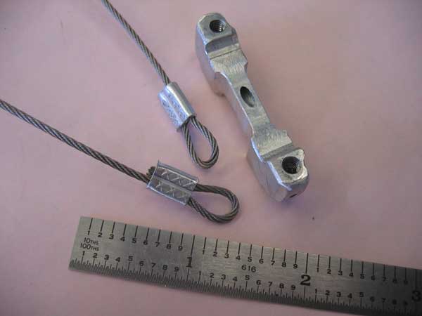
[January 15, 2011]
A visitor from France has been staying with us -- Vincent Legeay, who is in a Master's program in philosophy at the Sorbonne and is currently taking classes at U Mass and teaching French at Amherst College. We spend quite a bit of time discussing the prosody of Rimbaud, a topic in which I have an inexplicable interest. We flew out to Death Valley yesterday so that his experience of California could include something other than the many wonders of Los Angeles. On the return I got pilot reports of moderate and even severe turbulence over the mountains north of L.A., and so I stayed at 12,500 until we were over the San Fernando Valley and then descended somewhat rapidly. As it turned out, either this plan worked or there was no turbulence to start with, because we didn't run into much. It was glassy, warm and calm all over the desert. Vincent, dans l'avenir quand tu chercheras ton nom avec Google, tu te souviendras de ce vol.

Vincent Legeay in Melmoth 2, above the middle of nowhere.
[January 6, 2011]
I investigated the stiffness of the trimwheel and found that it was due to the grease in two bushings and jackscrew up in the T-tail joint having dried out. I guess I could use better-quality grease -- there are certainly lubricants that don't evaporate, or leave no residue when they do, and that don't stiffen up at low temperatures -- but instead I cleaned the offending parts with acetone and reassembled them dry. Metals of dissimilar hardness, like steel and aluminum, make naturally good bearings, at least at low rotational speed, even with no lubricant, so at least the two journal bearings should be all right. Both the male and the female components of the jackscrew are hardened, so I don't know how well they will work together; they may require a lubricant. At least the trim now works freely again, but I think I may still enlarge the trimwheel just to make it more sensitive.
[January 4, 2011]
From time to time I have mentioned that Melmoth 2's parasite drag coefficient is .022 (roughly) and I have commented that this is not especially low. Nevertheless, compared with a Mooney 201 (for example), whose parasite drag coefficient is said to be .017, M2 requires less fuel to achieve a given speed. To clarify this apparent contradiction, it must be said that parasite drag coefficient, although it seems like a nice, pure, technical way of expressing drag, is really almost meaningless, because it is based on wing area, which is used as a stand-in for the complete airplane. Obviously, this makes little sense; you could shrink the wings of an airplane and its drag coefficient would go up even though its drag would have come down. M2's wing area (105.4 square feet) is much smaller than a Mooney's (175). If M2 and a Mooney had the same drag, the Mooney's parasite drag coefficient would be .013, which would be fantastically low. (On the other hand, if Melmoth 2 had more wing area, it would also have more drag.) Some aerodynamicists prefer to cite a wetted area drag coefficient, which is based on the total surface area of the aircraft and therefore is theoretically more reflective of its size than wing area alone is; but actually from the point of view of the human occupants it would make more sense to base a drag coefficient on cabin volume or useful load or number of seats or some other ingredient or combination that might reflect the utility and perhaps even the comfort of the airplane. Equivalent flat plate area, or "drag area," which is a way of expressing actual drag, is closer to reality than parasite drag coefficient is; M2's is 2.3 square feet, the Mooney 201's is (according to at least one website) either 2.8 or 2.97, depending which numbers you use.
Fuel flow is not a good basis for comparison either. The aforementioned website gives a cruising speed of 160 knots for a Mooney 201 at 10.5 gallons an hour, presumably at around 8,000 feet. M2 uses 8.2 gph at that speed. But mixture setting could account for at least part of that difference. Besides, all these numbers are highly uncertain; different airplanes are tested by different people under different circumstances and for different purposes, and there is little consistency in the results. When the data from many years of CAFE races were reduced to equivalent-flat-plate form, it was striking how much variation in drag area there was within a given type and model, even though the airplanes were all exactly the same size.
A reader commented, with regard to my previous posting, that GPS is unlikely to be accurate to one centimeter. This is true. When I said that the Appareo stores lat-long data with a precision of one centimeter, I intended to distinguish between precision, which is simply the number of decimal places presented, and accuracy, which is fidelity to reality. For the purpose of measuring groundspeed, an accuracy of one foot, or about 30 cm, is enough, and it doesn't have to be absolute accuracy, just consistency from one moment to the next. In other words, it doesn't matter if the GPS has the lat-long of the airport wrong, provided that the error remains more or less constant over time. If the error were large and it fluctuated wildly, one would expect the speed trace calculated from successive lat-long positions to be jagged or bumpy. It isn't, and so I feel pretty confident that the speed measurements are as good as they need to be, given the underlying fallacy of using groundspeed as a surrogate for airspeed. The real question is, how precise, or accurate, is a limp windsock?
[January 2, 2011]
Last night, curious about whether the groundspeed data from the Appareo were being massaged in any way, I dumped the file to Excel and added a second groundspeed based on the variation, at 1/4-second intervals, of latitude and longitude, which the program stores with a precision of about one centimeter. I was initially disappointed to find that these instantaneous groundspeeds did not match the reported ones very well. Here is a plot of the two; blue is the Appareo output, red the values calculated in Excel from the raw lat-long data. (The four vertical red segments are spurious outliers.)
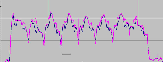
It's noteworthy that the lines coincide closely when speed varies in the same direction for a long time; but when speed is fluctuating somewhat randomly (for instance on the downwind leg) they get pretty far out of sync with one another. The Appareo line is evidently being smoothed or averaged somehow. My first reaction was dismay, but on closer examination I found that the portions of the lines that are of interest to me -- the areas during flare and touchdown -- coincide within less than a knot. The instantaneous values tend to be slightly lower than the smoothed ones, meaning that touchdown speeds are a bit lower than I thought -- about 50 knots with full flap at 1,900 pounds.
Unfortunately, the disparity between the two lines is greatest on the one landing that I did without flap -- the second-to-last in the graph -- and so I am no closer to a baseline to which to compare the flaps-down performance than I was before. The actual touchdown speed was several knots below the recorded 75, but how many I don't know.
[December 31, 2010]
Surprisingly, after the rain ended on the 29th there was a period of calm before the winds picked up, and, as I happened to be at the airport, I flew a series of touch and go's hoping to establish the touchdown speeds with various amounts of flap. (Touchdown speed is slightly different from stalling speed, because of ground effect.) I got my data, but it turns out to be harder to make sense of than I expected. The problem is that all of my landings were very smooth (of course!), and so there is no indication of the moment where the wheels touch the ground. Altitude doesn't work, because there is essentially no change in height from before touching to after. Furthermore, the Appareo software uses some sort of smoothing algorithm on vertical speed, so the vertical speed reported on the graph is not an instantaneous one. I can dump the data into Excel and fiddle with different moving-average schemes to come up with a better sense of instantaneous vertical speed, but that doesn't solve the more basic problem of being unable to tell at precisely what moment the landing occurred. I'm going to try pitch angle, although there too there is a problem, because it can increase momentarily after touchdown as I hold the nosewheel off.
Here is the record of the flight; if my subscription had not lapsed, it would have Google Earth surface data rather than a green grid for the background:
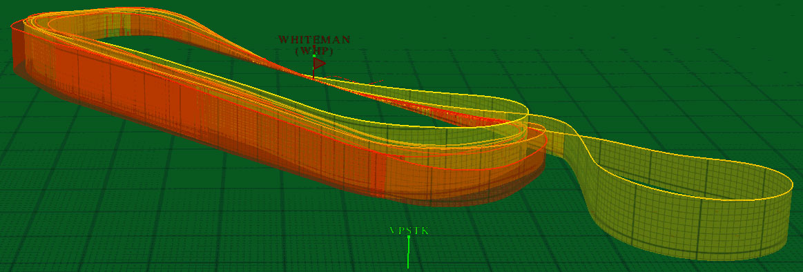
I took off from Runway 12, but after my first landing the tower changed the Runway to 30; hence the teardrop on the right. Weight was around 1,900 pounds, for a wing loading of 18 pounds per square foot. Airbrake was used with all landings; it contributes some lift. A lift coefficient (for the complete airplane) of 2.15 would be required to maintain 50 kias at this weight. My approaches are not particularly consistent.
Here is a typical graph generated by the software that comes with the instrument. You have your pick of ten parameters to plot; in this case, altitude (brown) is shown along with groundspeed (green). Of course, groundspeed isn't airspeed, but the windsock was limp during most of these landings. A movable cursor selects data for a particular moment; in this case, it is the lowest point on a circuit, which you would think would represent the ground; but maybe not. The software allows you to reconstruct all the flight maneuvers and review them from inside or outside the airplane, Flight Simulator-fashion.
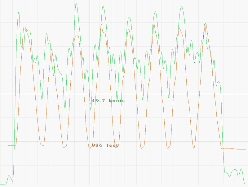
If I add ground elevation to the plot, I see this interesting pattern:
The descending lobes represent the glidepath, roundout, ground roll, and takeoff. The duration of the segments where the lines are parallel is about 15 seconds, the altitude gain is 15 feet, and the average speed about 47 knots; that's about 1,185 feet. The runway rises about 50 feet over its 4,000-foot length, so the numbers are reasonably consistent. The gap between the two lines is due to some combination of the height of the instrument above the ground (about 5 feet) and GPS error.
So, on the assumption that the touchdowns occurred slightly to the right of the point where the two lines become precisely parallel, I get the following values for touchdown groundspeed:
30 degrees (landing) flap: 55.3, 50.2, 50.7, 40.4
10 degrees (takeoff) flap: 60.5, 56.8, 57.9
No flap: 75.4
The last full-flap figure seems way too low, and the no flap figure seems way too high; the power-off flaps-up stalling speed measured by Mike Melvill in 2002, when the airplane was about 200 pounds lighter, was 68 knots. But the results, such as they are, do suggest that my impression that the flaps took 15 knots off the landing speed is correct and not an artifact of pitot-static error.
I still need to see whether the reported airspeeds are instantaneous or, like the vertical speeds, moving averages.
Happy new year to all readers, wherever you are.
[December 28, 2010]
Yesterday I picked up Javier Arango's Appareo flight data collector, hoping to do a series of touch-and-go's to compare touchdown speeds with zero, takeoff and full flap. It was a perfect day for testing, with almost no wind. Unfortunately, when I started to record a flashing light told me that there was "no memory." I concluded that the flash card must be full, and so just went up and flew around for half an hour, cruising lazily around at 1,000 or so agl at 120 knots and 6 gallons an hour. On taking the whole rig home to charge it and empty the flash card I discovered that the problem was actually not that the flash card was full, but that it was not even in the device. It was in a card reader that came with it. Unfortunately, a cold front went through last night, and there are supposed to be advisory-level winds in the San Fernando Valley today, so I won't be able to conduct the test for a while.
It finally dawned on me that a solution to the stiffness of the pitch trim wheel -- a minor irritation that I have not previously mentioned here -- would be to use a trim wheel of larger diameter. Duh. Really, I am an idiot. I was so focused on trying to understand why the trim was stiff in the first place that I failed to see that the ready answer -- as I should know, living in gang-tormented Echo Park -- is brute force.
[December 18, 2010]
I dug up and scanned some old pictures taken during the construction of Melmoth 2. They're in a new section called "Construction" that is reachable from the home page.
[December 16, 2010]
I have been wondering why the #1 cylinder (right rear) runs hotter than the others. I had the cowling off for an oil change (not a single drop of oil leaked from the inverted oil filter, by the way) and I realized that the two hoods that I installed to direct cooling air over the unfinned surfaces of the exhaust ports on the #1 and #6 cylinders, and that had been effective in lowering their CHTs, were operating under somewhat different conditions. Air entering the hood on the #6 cylinder (left front) reaches the hood before it reaches the exhaust pipe. Air arriving at the hood on #1, however, passes over the exhaust pipe just before it enters the hood.
One of the objections to updraft cooling that I frequently heard during the design phase was that cooling air would be pre-heated by the exhaust pipes on its way to the cylinders. I reasoned that, air being a fairly good insulator, only the air in the boundary layer of a pipe would pick up much heat, and this would be a small fraction of all the air passing through the cowling. I think this reasoning is generally correct; on the whole the engine tends to over-cool, not under-cool. But local flow conditions may violate the general principle, and I think that may be happening here. This what the hood looks like:
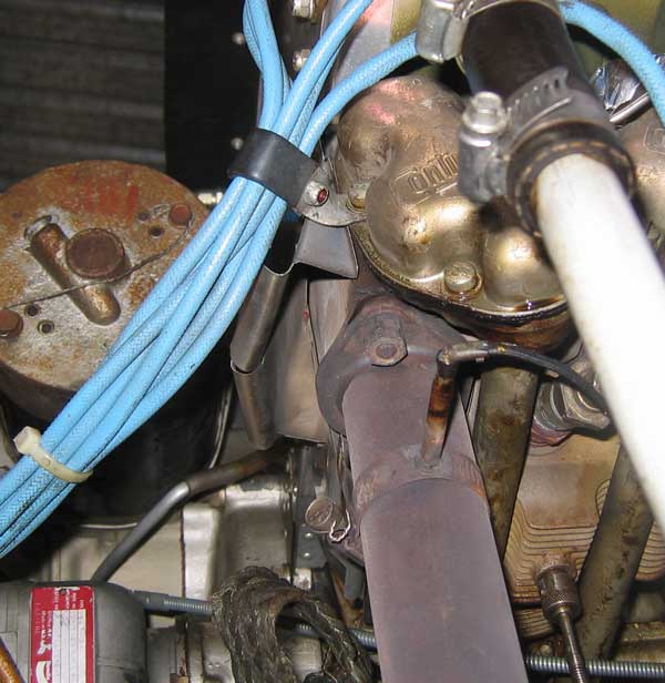
Some, if not all, of the air entering the hood (the sheet-metal thing with the curved lip) is probably coming right out of the boundary layer of the exhaust pipe. It seems obvious that I ought to reshape that hood so that the air enters it from a different angle; I need to give a little thought to what that angle would be. I've occasionally thought about putting some tufts in the cowling and observing them with my miniature TV camera, but I've never seen tuft tests inside a cowling, and it may be that the flow is so chaotic that no useful information can be obtained.
Yesterday I spent quite a while thinking about where to put the three switches and one dimmer that will control the nav lights, flashers, pitot heat and panel lights. This is the kind of decision that is easily made on a crowded panel when it takes ingenuity to find any space at all. In this case, I had an empty area of 6x8 inches in which I could arrange the switches any way I liked. The infinitude of choices paralyzed me entirely.
[December 4, 2010]
I rerouted the wires in the flap coves yet again, on both sides. This time I think I got it right. None of the wires appears to be in any danger, even after years of vibration and neglect, of being frayed by any moving part.
In the course of raising and lowering the flaps I found that I have not been allowing the hydraulic pump to run long enough after the flaps reach the retracted position to completely equalize hydraulic fluid volumes in the master-to-slave lines, and as a result, for reasons that I do not understand and very likely never will, the right flap, over time, extends less and less far. From time to time I would correct the symmetry by opening the bubble catchers on the right side, pulling the flap all the way down, and adding fluid. It never took much -- a couple of tablespoons at most. But the small increment seems to make quite a difference. Fortunately, the ailerons have had no trouble overcoming the worst flap asymmetry that has yet occurred. I suspect that this may mean that increasing the angular deflection from the takeoff position, nominally 10 degrees, to landing, nominally 30, may be adding more drag than lift. Although the flaps are obviously very effective, I do not have a good handle on landing speeds, other than occasional glances at the ASI. I need to borrow from Javier Arango the Appareo flight data recorder. By flying a series of touch-and-go's, maybe three each with flaps set at zero, 10 and 30, I should be able to get a handle on the actual effect of the flaps. I suppose I could do the same thing with the Lowrance GPS in the airplane, but I'm not sure what its update rate is. The Appareo's is 4 per second.
I had a nice flight to Camarillo for lunch with Russ Hardwick on Thursday last. At 4,000 feet we doing 140 ktas at 6.9 gph -- about 41% of power, or 82 brake horsepower. This would have dropped to 135 ktas or so if we had had another pair of passengers in the back.
[November 14, 2010]
Having talked so much about having to refinish the kitchen floor, I might as well display the results. Here is what it looked like when we started in June:
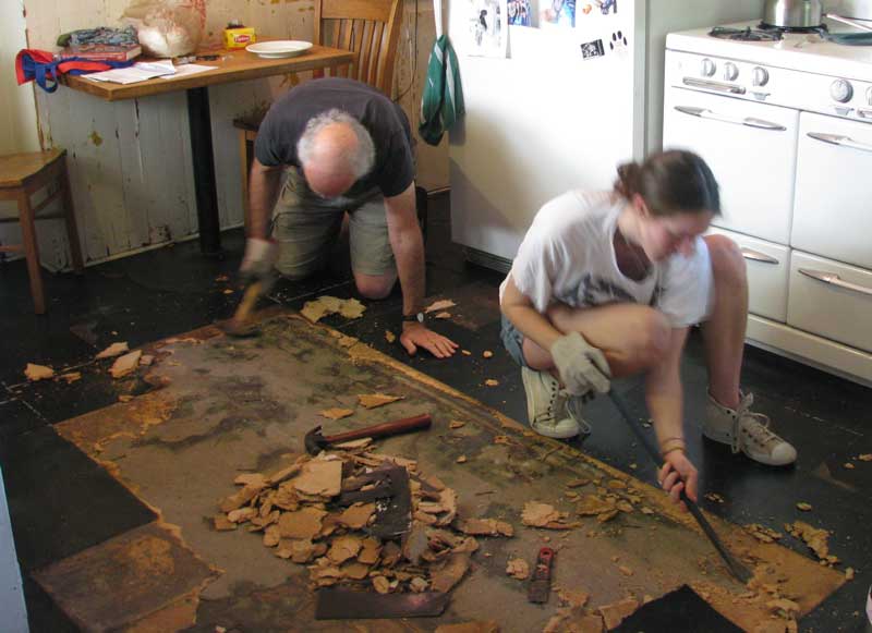
The black vinyl tiles were in a dilapidated condition; under them was a layer of 3/8" particle board, and under that was a layer of felt or heavy paper of some sort, held down by thoroughly hardened tar. This had been a substrate for a linoleum floor that had since been removed. Under it was the damaged but salvageable 100-year-old subfloor of clear Doug fir. It took me a couple of months to remove the tar and paper with a paint scraper. Here is the final result:
It is discolored in places, scarred with nails, and patched where walls used to be or people cut out parts of it to gain access to the underside; but it looks nice now and feels good under one's bare feet.
On matters of greater international importance, I managed to feed the required additional wire from the nav light cove through the inaccessible void at the root of the upturned wingtip and out through a tiny hole into the aileron cove. I am now stringing it down to the fuselage, using a different routing than I used on the left side. I am happier with this one, and I'm going to go back to the left side and reroute the wires there.
[November 2, 2010]
I've barely gotten to the airport lately, but I put in a couple of hours today stringing wires from the left wing toward the fuselage. The wingtip has roll trim, nav light, a white halogen flasher and pitot heat, and the outboard fuel sender joins the parade at BL135. I did a very poor job of anticipating the need for a conduit for all these wires. I assumed there would be plenty of room along the rear spar, but it turns out that there are a few spots where it gets tight. I'm still not even sure I've done the smartest job of routing the bundle; I'm thinking maybe I should undo everything I did today and start over. I'll sleep on it.
[October 25, 2010]
Flew to Camarillo for lunch on Saturday with a couple of friends. One is a pilot (actually, both are, but the other flies only sailplanes) and he flew the outbound leg. After we landed, the tower asked us to expedite because of landing traffic, but did not use the "ground point eight leaving the runway" phrasing, so when we got to the taxiway we didn't know the ground frequency. My friend kept taxiing -- there were no other planes around -- as we tried 121.9 and then went back to the tower to inquire. Turns out it's 121.8. Anyway, as we taxied toward the restaurant he got the dreaded "After shutting down call this number" call. I had no idea what the problem was; I thought maybe we had gotten too close before calling the tower or had annoyed them by dropping down to 1,200 to stay below clouds when we had been instructed to maintain 1,500. But it turned out that the problem was that we had continued rolling while not in contact with ground control. He had several phone conversations with them with no result that I know of. He's an international airline captain, and left the next day for Europe. I assume the FAA just wanted to call the infraction to his attention. Anyway, live and learn; if you don't know the ground frequency, stop after leaving the runway and get it.
[October 13, 2010]
I have said, not altogether facetiously, that the advantage of oil leaks is that they can tell you things about airflow patterns. Here is an example. Predictably, air leaving the engine compartment around the cowl flap wants to emerge at a right angle to its steeply raked leading edge. On the inboard end, it is impeded by the wall of the chute; at the outboard end, on the other hand, where the gap is quite small, the flow does emerge at approximately a 40-degree angle to the flight direction. Shearing forces from the free stream tend to align the exit air with it; the oil streaks (the inner ones are quite faint) show both the process of alignment and the effect of the inboard wall on the flow direction.
[October 10, 2010]
Recently the right main landing gear strut developed a propensity for collapsing whenever I turned left off the runway after landing. By collapsing I mean that it compressed abnormally, so that the plane rolled along in a drunken attitude, right wing low, and, in one instance, fuel actually dribbled out of the right tip vent. As I continued to taxi in this embarrassing posture, the strut would gradually resume its normal height. If I tested the strut pressure by bouncing the wings up and down, the plane settled in a level attitude. A mechanic whom I asked about this behavior diagnosed it as a low fluid level. This makes sense; as the fluid level declines (through slow leakage past the piston O-ring, I suppose) more and more air takes its place, and the spring rate of the strut changes, making it "softer". Indeed, I don't believe I had added fluid to the right strut in the past eight years; so I jacked up the airplane and refilled the strut. This is a simple operation, which involves a special strut-bleeding tank acquired, I believe, from Aircraft Spruce. The tank is simply a plastic reservoir with a quart of hydraulic fluid in it and a pickup tube that connects to the strut's air valve with a fitting that depresses the valve plunger, allowing air and fluid to flow freely in or out. You compress and extend the strut two or three times, until air ceases to bubble into the tank. You then compress the strut fully, disconnect the tube, and finally fill the strut with air, using a strut pump, until about three inches of piston shows when the weight of the plane is on the strut. It is, by the way, incredibly difficult to compress the strut when it is full of fluid; you are not only lifting the weight of the wheel and part of the strut, but also forcing fluid through a tiny orifice.
Unfortunately, through some combination of stupidity and inexperience I did not think to drain the old fluid first, and so I ended up with a mixture of old, dirty fluid and new fluid in both the strut and the tank. I'm not sure how much this matters; it's possible that the viscosity of the fluid declines with age, but I have yet to make a bad enough landing for it to matter. I suppose, however, that I should do it again, on both struts, this time discarding the old fluid. Annual inspection time rolls around in November. The only way to get all of the old fluid out of a strut, however, is to remove the strut from the airplane and turn it upside-down, a requirement that just about triples the annoyingness of the task.
[October 3, 2010]
The kitchen floor is finally finished, but it has unfortunately reinforced my reputation for being able to make tolerable house repairs.
Last week I began wiring the nav lights. My usual scheme is to use a single shielded wire for a circuit, carrying the return through the shield, and I had accordingly run two wires to the light cove, one for the nav light and one for the halogen flasher. But Paul Lipps, who designed the flasher circuit, informed me that a single coax could not be used for the flashers; I think the reason is that part of the time the positive current would be in the shield, and would create radio noise. So I had to add a third wire. I thought it would be tricky, and it was, but I got it done on the left wing. The right will be trickier still, I know. The tail lights, on the other hand, will be very simple.
I've decided to do the revised turbo inlet duct next, but I am still trying to find out how best to turn a stream of air 90 degrees in zero distance. This seems like a rather obvious problem that people must have faced countless times, but I can't figure out what the search terms are that will bring me enlightenment.
[September 21, 2010]
We were away for a couple of weeks on our annual late-summer retreat to Cape Cod and environs. Yesterday I got out to the airport for the first time since returning. I just needed to pick up some tools for the perennial kitchen-floor project, but it was moving to see the plane again. "You're looking pretty good," I said aloud -- somewhat embarrassing, since I do not normally speak to inanimate objects, though I suppose there is no reason one should not. Even people often have no idea what I'm talking about.
I am tossing around in my head various ideas about what to do next. Obviously I need to wire the lights, but that's a minor chore. The major candidates are:
1. Replace the banjo box at the turbocharger inlet. I have come to feel that the 2-inch duct from the air filter to the turbo is too restrictive; air going through it must accelerate to nearly 200 mph at high power settings. Engine breathing would be improved by a larger duct. There are space restrictions, but I could probably enlarge the duct by 50%.
2. Reduce the aileron hinge moments. I have always felt that the stick forces in roll are too high. There are various ways to reduce them, including certain trailing-edge modifications, a simple servo tab, or new ailerons with more aerodynamic balance and the hinge line farther aft. The high forces are due to the cusped shape of the airfoil; they could be reduced by straightening the contours and using a beveled trailing edge, as Mooney does, but that is an ugly solution. There are possible flutter issues with a servo tab. Aerodynamic balance requires much larger gaps between aileron and wing. I have delayed doing this for a long time because I find the decision so difficult to make.
3. Revise the intake manifold. The present arrangement of the intake manifold seems to me illogical, given the arrangement of things in my cowling, and it clutters up the outlet path for cooling air. I would like to turn the manifold around, putting the throttle body above and behind the accessory case. This would be a pretty major modification, however, and its benefits are uncertain.
But first, the kitchen floor.
[August 23, 2010]
Assembled the tip lights just to make sure they would fit. I still have to add some wiring, etc. The white bulb is a halogen that is on a flasher circuit with the other tip and a similar tail light. The whole arrangement is quite primitive compared with modern LED lighting, but it has the great advantage of being practically free, since I already had the nav light assemblies left over from Melmoth 1. No doubt LEDs are brighter, last longer, and draw less current, but whether any of that affects one's enjoyment of flying, I don't know. I doubt it.
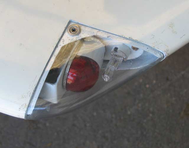
[August 11, 2010]
What with the removal of a wisdom tooth, lots of writing to do, the kitchen floor (still scraping; I can do three square feet an hour) and an unusual amount of software support needing to be provided to some new customers, I haven't been to the airport much. I did, however, do a cold compression check. The engine has about 1,200 hours, and the compressions were 78,77,78,78,77,71. The mechanic who lent me a compression tester commented that the next time I check it, the 71 will have become a 77 and a 78 will have dropped to 74. In other words, compression checks are not exact science. In fact, he considered them less useful than a sensitive ear for judging the state of the engine.
I began to fit the nav lights into their coves and promptly found that the mounting of nav lights and halogen flashers that I had painstakingly arranged would not fit comfortably under the lenses. Starting over.
[July 31, 2010]
Got back from Oshkosh this morning after a 3.7-hour flight from Santa Fe, where I had stopped for the night. The return took 10.3 hours in all, 1.1 more than the trip eastward; part of the excess was due to less favorable winds and part to the longer southern routing and some deviating around cells while leaving OSH and during an IFR stretch between Gallup and Prescott. The difference between block speed (takeoff to landing) and en-route speed is always surprising. Although I saw 180 knots or better on the GPS during almost all of the eastward trip and true airspeed around 176 knots at 12,000 feet, the block speed was just 168 knots. Overall fuel burn was around 8.8 gph, for a cost of $0.237/mi. Average fuel price was $4.61/gal.
Despite its annoying habit of dispensing a fine mist over the windscreen, the engine used only about one quart of oil per 15 hours. The trip was glitch-free, except for the nuisance of not being able to shut off the back seat ventilator from the front. I finally realized that a simple solution to that problem would be to put a remote-controlled butterfly or flapper valve into the duct leading to the vent. My brain had been stumped for a long time by the puzzle of how to control the vent from the pilot's seat. The adjustable outlet was taken from a Camry and its controls do not lend themselves to remote actuation. A separate valve upstream, however, would be comparatively simple.
The current arrangement of padding on the pilot's seat seemed to be pretty successful, although I started to experience some discomfort after 7 or 8 hours in the air. Maybe I can finally replace its pillowcase with genuine faux leather. I did somewhat miss having armrests.
Lately a couple of people have told me, without apparent embarrassment, that Melmoth 2 is quite ugly. One called it something only its designer could love, while the other confined himself to merely admitting that he liked Melmoth 1 better. I attribute their lack of inhibition to a sense that the fact is so obvious that there is no point avoiding mention of it, although the same reasoning does not, I believe, apply to babies. Fortunately, my granddaughter is extraordinarily comely. On the other hand there was general surprise (and I'm sure some unexpressed disbelief) at Oshkosh about a four-seat plane's cruising at 170 knots on 8.2 gph. Glasairs and such small deer do the same speed on 6, so I'm sure it's not that difficult. In fact, Melmoth's parasite drag coefficient (0.022) is not even remarkably low. It must be that those of certified airplanes (with a few exceptions) are comparatively high, or that their pilots do not lean the mixture as aggressively as I do.
While at OSH I talked briefly with Johnny Doo, Senior VP for Engineering and Product Integrity at Continental. I asked his opinion on the question of whether temperatures indicated by a bayonet thermocouple would be different, for a given overall cylinder temperature, in an updraft-cooled engine than in a downdraft-cooled one. He said he did not think there should be a difference. This confirmed my and Mike Melvill's opinion that since the bayonet is close to the exhaust port and the exhaust port is the hottest part of the head, the recommended bayonet reading would be the same in either case.
[July 28, 2010]
At Oshkosh. I took off from Whiteman Monday morning, IFR to VFR on top, and flew through an 800-mile convective sigmet that turned out not to be too big of a deal except for some moderate chop over the Rockies approaching Denver. I landed after 5.4 hours at Sidney, Nebraska, having used 45 gallons. On to Prairie du Chien, WI -- I sometimes pick stops based on proximity of airstrip to town on the map, and the attractiveness of local contours or, in this case, bodies of water -- in three hours, 26.8 gallons. There was a motel right across the street from the airstrip; left early the next morning, short but beautiful glassy flight over misty fields, and got into OSH a little after 7:00. Lots to see here, some amazing, some crap.
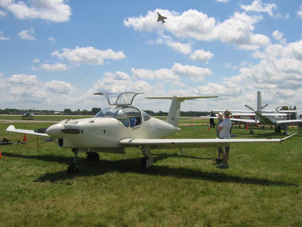
[July 20, 2010]
Except for countersinking the screw holes and installing lock-nutplates inside, the nav light lenses are done. They fair in nicely, in spite of having been formed over the outside of the wingtip. It remains only to put something under them.
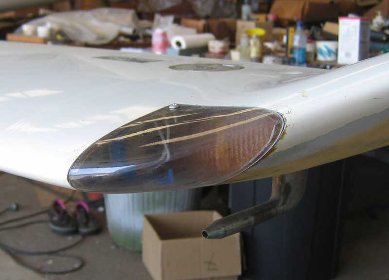
[July 15, 2010]
The nav light lenses came in the form of lumps in a flat sheet of ploycarbonate. They reminded me of those loaf-like mountains in Chinese travel posters. It turns out that this plastic is so tough that it can readily be cut with tin snips, and so it was quite easy to trim away the excess material. Here are a couple of lenses, together with the tool that was used to form them. The tool consists of the actual pieces of leading edge skin that were cut out for the nav lights.
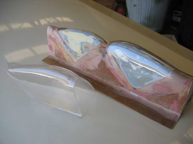
At my request John Eggett had made me two pairs. One I trimmed to fit and then cut in half along their leading edges. I taped the halves in place -- yesterday top, today bottom -- and laid up a couple of plies of fiberglass on the inside to serve as supporting flanges. I hope to be able to hold the lenses in place with just two screws, one each at the upper and lower corners. Here the upper flange is done and the lower half-lens is in place for laminating.
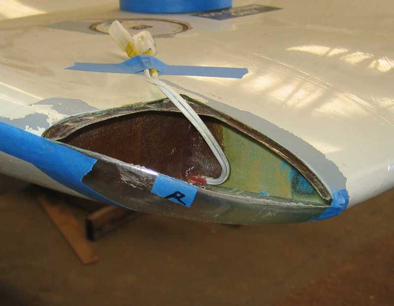
I am not very good at making paint stick.
[July 10, 2010]
The guys at Pacific Continental were very understanding about my failing to buy the intake manifold for $1,400 after they had located it, cleaned it up and alodined it. They confirmed that the throttle body can be in any position; it is a remarkably simple device -- they happened to have one on the bench -- consisting of a lopsided disk that slides across a small hole, gradually occluding it; this little hole is the fuel passage. What I need to study now is how to support the throttle body and where it will fit behind the engine. There is also a question in my mind about how tight a bend I can make in the 2.25-inch duct that will go from the turbocharger to the throttle. The intake manifold itself uses 2-inch tubing and bends of 4-inch radius on the tube centerline.
I picked up the nav light lenses on Friday. They are made of a polycarbonate that can be cut with a bandsaw and evidently lacks the propensity for cracking that makes plexiglas such a delightful material to work with. The question now is whether they will pull down to the leading edge radius -- they were formed on male molds that exactly match the wings, and so they are oversized by the thickness of the material. They seem pretty flexible, and so I am optimistic.
I have scraped the tar paper from about 60 percent of the kitchen floor now. It has taken three weeks. My right triceps is in great shape.
[July 7, 2010]
The absurdly high readings on the #5 CHT turned out to be due to the bayonet having fallen out of the cylinder head and ended up with its tip resting on an exhaust pipe. That is my one new CHT bayonet, and it has a crummy metal stamping for a retainer, unlike the more massive cast retainers on the others. Crummy though it is, however, the retainer still works if it's twisted on properly. Visual inspection of the dead EGT probe didn't reveal anything. Yesterday I had my biennial pitot-static check, and the mechanic who did it remarked that EGT probes fail pretty regularly; still, it could be a loose connection, perhaps behind the panel.
Pacific Continental Motors, an overhauler at Whiteman, called to say that they had found an intake manifold. During the episode of the worn-out starter clutch I had talked with them about my idea of reversing my intake manifold in order to keep it from obstructing the way to the cooling air outlets. I'm amazed that they actually remembered and did something about it, but now I'm also worried that I'm indebted to them and they're going to want some huge sum for the manifold. What I really wanted was to modify a spare manifold in advance, and then give whoever lent it to me my old manifold in exchange when I take it off. All this is by way of not grounding the airplane for too long. But I'm thinking now that maybe I could actually do most of the prep work before taking my engine apart. It's a fairly complicated job that involves not only the manifold but also the throttle body and throttle cable, air ducting between the turbo and the throttle, and the fuel plumbing between the throttle and the fuel pump and fuel distributor, but the simplification that occurred to me was to splice the manifold, where I intend to saw it apart, with rubber sleeves rather than by welding. This would be cheaper, and would also involve less risk of things not fitting together. Most of the other components could be prepared in advance without my actually having to dismantle the engine.
John Eggett, a neighbor of mine at the airport, formed nav light lenses for me, and they're ready for pick up. I may get them on in time for the trip to Oshkosh. If not, no harm. I no longer fly at night anyway.
[June 29, 2010]
I flew the plane for about 40 minutes yesterday afternoon. The OAT at 7,500 feet was 75 F., or about 43 F above standard, and the oil temperature never dropped below about 88 C (190 F). This was a little disappointing, but I suppose one has to make some concessions to atmospheric conditions. I will obviously not have the nav lights working by the time I leave for OSH; but I hope I will at least have the #5 CHT and #3 EGT back in line (the former is indicating a cylinder temperature of 650 and the latter is indicating nothing at all; neither can be correct).
There is always a fine mist of oil in the middle of my windscreen after I've flown. I attribute it to many little seeps in the engine, which sat for 20 years, its seals slowly hardening, while I was building this airplane. Oil droplets are picked up by the updraft airflow and come out the upper-surface vents. Most are carried to one side or the other without striking the windscreen, but those that arrive at the stagnation zone in the middle remain. Yesterday there was more oil than usual. I attribute it to my not having flown the plane for almost seven weeks, and more than the usual amount of drips having collected on the underside of the engine. But I will have to keep an eye on it.
Mac McClellan tells me that the FCC's crazy ban on 121.5 ELTs is being held in abeyance for the time being. That's a relief. I really needed to pay $1,500 for a new ELT.
[June 28, 2010]
No sooner did Nancy and I get home than I began work on removing our kitchen floor, which consists, or consisted, of black vinyl tiles decomposing upon a stratum of cratered particle board. The particle board came up easily, especially because Lily did most of the crowbar-wielding, commenting, no doubt with her just-ended years of academic labor in mind, that it was pleasant to do work that produced visible results. Underneath it is 100-year-old fir tongue-and-groove flooring, which, with some repair, will, I hope, take a finish and produce a nice rustic effect. First, however, the tar paper on it has to be removed, and this has turned out to be a major challenge. It is heavy paper, and has been stuck to the wood, and pressed down by generations of feet, for so long that the two have practically become one. It takes all my strength to scrape up some sections of it -- others lift more easily, having been less well secured to begin with. Irons, hair dryers and even floorers' heat guns have limited effect. I will soon be reduced to hiring a helper of fewer years and more muscles. All this is by way of saying that I have not been to the airport. Instead I have been stroking my aeronautical fur with mental images of reversed intake manifolds and revised air intakes. Four weeks til I leave for Oshkosh. I intend to fly this afternoon, to remind myself where the buttons are.
[June 8, 2010]
Nancy and I flew (commercially) to Providence on May 24 to watch our daughter graduate from Brown, and we are now on Cape Cod helping a friend clean up her summer house, which had some modifications done by workers apparently unacquainted with the concept of dust covers. We won't be back in LA before June 15.
I'm planning to go to Oshkosh this year. I'd like to get the EGTs and CHTs all working properly before that trip, but otherwise will not undertake anything very ambitious between now and the end of July. I am thinking about sleeping in the plane on that trip, or at least at Oshkosh, since I haven't made any reservations; it would realize a childish fantasy of footloose-and-fancy-free airborne wandering that I had when I designed the plane, but have never actually tried.
[May 14, 2010]
I finally added the bellmouth to the oil cooler duct inlet. It's unlikely to have a major effect on oil temperature, which has already dropped by 45 deg. F, but it just seemed like the right thing to do.
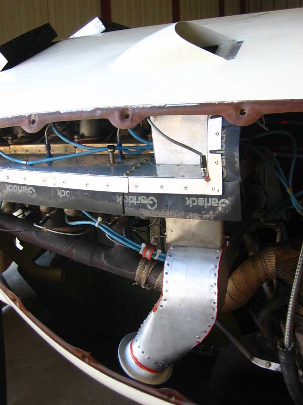
Readers who have followed this slowly unfolding saga will recall that the point of the elaborate duct was to provide the oil cooler with a flow of air that is 1) unheated by passage over the exhaust pipe and 2) unthrottled by the cowl flaps. As is apparent from the graph which I posted on November 9 of last year, the pressure drop across the engine is strongly influenced by the cowl flap setting. The difference between the pressure in the high-pressure plenum and ambient is larger than shown on that graph; when the cowl flaps are closed, it is about 12 inches of water at 140 kias -- nearly the dynamic pressure. According to Stewart-Warner's data on my oil cooler, a pressure drop of 12 inches of water implies a flow rate of 90 pounds of air per minute, or about 19 cu ft/sec at sea level. At a forward speed of 170 ktas or 285 ft/sec, this corresponds to a steam tube with a diameter of 3.5 inches, which is, in fact, exactly the diameter of the duct inlet. Since the air in the plenum is essentially stationary, it must accelerate to 285 ft/sec as it enters the duct; hence the need for a bellmouth to prevent the flow from separating on the sharp edge of the duct. These numbers are highly theoretical, naturally; there are bound to be all sorts of losses in the system. It would be interesting, however, to put a pitot tube behind the outlet hood and see what the velocity there really is.
By the way, the gray wire terminating in a quick-disconnect on the horizontal baffle goes to the electric cowl flaps.
[May 6, 2010]
I made a mess of the engine instrumentation the other day. The #1 cylinder CHT is working now; but the #3 CHT is intermittent and the #3 EGT has stopped working altogether. Evidently I disturbed them, to put it mildly, while fixing #1, which, by the way, turns out to be hotter than the other cylinders. That was disappointing; I thought I had corrected the tendency of #1 and #6 to run hotter than the others.
I was at Paso Robles yesterday and on the way back stopped at San Luis Obispo to see whether Don Dominguez at San Luis Avionics could figure out why my glidepath needle was motionless. He did; there was a broken wire on the little motor that drives the needle. He re-soldered it and now it works. While he was bench-testing the instrument he observed that the nav flag seemed to be inop. I was embarrassed not to have noticed it. He tried to fix it, decided that the actuator motor was faulty, and we discussed finding a replacement. I then took off southbound, tuned in the Santa Ynez VOR, and the nav flag worked fine. I realized that the reason I hadn't noticed that it wasn't working was that it wasn't not working. Why it failed on the bench is a puzzle.
The airplane was parked at a peculiar angle outside San Luis Avionics, and the fuel in the left wing went out to the tip. The pressure in the left main strut was low, and I had a hard time getting the plane to sit level enough for the fuel to drain back inboard. That's a problem with my rather small (3.2 degree) dihedral angle. I have never filled the tanks to capacity (71 gallons on each side) and so I don't know how bad it can get.
I still haven't gotten around to making the bellmouth for the oil cooler duct inlet. I need a short piece of tubing 3.5 inches in diameter, and I'm only slowly getting over my annoyance at Industrial Metal having a $6 minimum cutting charge. It used to be 50 cents.
[April 30, 2010]
On the 28th I set out to bring the dead CHT indicator in the #1 cylinder back to life.
To begin with, I knew the bayonet probe -- these are the old AN probes that stick up into the cylinder head casting -- was good, because I had previously swapped it with another. And I knew the instrument was good, because I have six cylinders hooked up to a twin-engine gauge by way of a three-position selector switch, in such a way that the rear, middle, or front cylinders' CHTs can be displayed in pairs, and all the others worked. So the problem was somewhere in the wiring. The wiring consists of the pigtails that are part of the thermocouple assembly itself; a length, equal among all probes, of special thermocouple wire whose electrical resistance is little affected by temperature; a 12-pin Molex connector; a short length of ordinary wire (we are now in the cabin, where temperature variations are small), the selector switch, a trimming potentiometer, a four-pin connector, and, finally, short lengths of ordinary wire going to the instrument, which has its own internal trimmers operated by two screws on the face. The likely culprits, I thought, were a broken connection either to the selector switch or the trimpots, or inside one of the Molex connectors.
The selector switch and the trimpots are in a single assembly with a connector at each end, and are located behind the instrument panel. Since the panel swings out, it was a fairly simple matter to remove the whole assembly and inspect and bench-test it for continuity. I found no problems. The wiring between it and the instrument was also evidently okay, because it is common to all three positions of the selector switch. Each thermocouple is electrically conductive, and by testing the conductor pairs in the 12-pin connector coming from the engine I determined what was by then obvious: that continuity in the faulty circuit was interrupted somewhere between the thermocouple and the instrument side of the 12-pin connector. The fault must be either in the engine side of the 12-pin connector or at the other end, where the special wires are connected to the thermocouple pigtails.
Since the 12-pin connector is comparatively difficult to get at, I decided to check the other end first, and immediately discovered that the cause of the problem was quite simple: an improperly crimped connector had come off a wire, producing not just a bad connection but no connection at all. I repaired it -- soldering as well as crimping this time -- and dipped the thermocouple in boiling water: 100 deg. C. (Actually, since the airport is at 1,000 feet agl the boiling point of water is around 99.5, but the instrument is too small, and the parallax too large, for half-degree differences to be discernible.) It may seem odd that I did not check that connection first, since it was easier to get at than the others. The reason was that I had checked it a couple of years ago when that probe was intermittent, and had found a loose screw and tightened it. I therefore assumed that the fault must be elsewhere.
It was oddly exciting to see that CHT probe working again, and I longed to go flying with it; but there was no time, and hasn't been any since.
[April 27, 2010]
Fans of the TV series 24 will perhaps find the person in the passenger seat familiar:
It's Arlo, the supposedly nerdy but actually cool guy who spies on all of Manhattan with a bunch of aerial drones. His real name is John Boyd, and he has been a great friend of my son's since they were both three. His girlfriend Nicole Vicius, also an actor and possessed of an unusually perfect philtrum, is in back. We are returning from lunch on Catalina, which is discernible through the rear window as a vague bluish undulation. I hasten to add that Nicole was in front on the flight over there; we do not make a policy of Mafia seating. Personally, I like the view backward, in life as well as in literature, and would sit in back if it did not make flying the plane so awkward.
I had put a folded paper towel in the cove in the right wing where the flap actuator leaks, hoping to find where the leak is coming from. When I took it out after one flight it showed considerably more blue stain than pink; evidently there is a fuel seep out there, which I have not been aware of because in local flying I seldom bring the fuel up to that level. I think minor fuel seeps are just something I'm going to have to live with, as if I owned an SR-71; it is impossible to get inside the wing to fix them.
Ever curious about engine temperatures, I calibrated my CHT system again -- I last did it seven years ago -- using a can of water brought to a boil with one of those plug-in one-cup tea-water heaters. The right bank of probes needed adjusting; they were indicating about 15 C. low. The left were right on. In fact, I found the consistency surprising; apart from the one probe from which I get no reading -- I'm going to try to track that problem down today -- four of the others indicated 100 and the fifth 98.
[April 2, 2010]
I collected some performance points the other day; I do this from time to time to see whether I'm gradually getting dirtier. I was at a density altitude of 10,000 feet. At 31 inches and 2,500 rpm, with a fuel flow of 9.4 gph, the indicated airspeed was 153 knots. This corresponds to an equivalent flat plate area of 2.3 square feet. For those who, like me, are fond of numbers, here is what the performance analysis routine in Loftsman makes of it:
Some of the headings may be less clear than others. ThpReq is the required horsepower to move a drag of 202.4 pounds at 153 kias; but because the prop efficiency (.857) is less than 100%, the engine has to produce 129 hp to yield 110.6 hp worth of work. Par/Ind is the ratio of parasite to induced drag; the induced drag is a little less than a tenth of the total drag. SFC, or specific fuel consumption, is the weight of fuel, in pounds per hour, consumed per brake horsepower. SpRange, or specific range, is the speed divided by the fuel flow -- in other words, nautical miles per gallon. BhpAvl is the available brake horsepower, which is 200 up to the critical altitude of the turbocharger, whatever that may be; the available thrust at maximum power would be 313.8 pounds. The 111.4 pounds of excess thrust (313.8 - 202.4) would yield a rate of climb at this speed of 1006.9 fpm (too much precision -- the calculation is not nearly that exact) and an angle of climb of 3.19 degrees. With zero power and thrust, the sink rate, again at 153 kias, would be 1,819.1 fpm, and the glide angle 5.78 degrees. The L/D ratio at 153 kias is 9.88 (the best L/D ratio, at around 100 kias, is 15.2 or so). Q is the dynamic pressure of air at this speed: 79.29 pounds per square foot. The lift coefficient for the complete airplane is 0.24, and the total drag coefficient is .0243, of which 0.022 is parasite and .0023 is induced. e is the span efficiency; the value, which is calculated somehow or other, seems unusually low; but at this speed it doesn't have a big effect on performance anyway. UnitRN is the Reynolds number per foot in millions, so that, for instance, for the wing's mean aerodynamic chord of about 3.2 feet the Reynolds number is around 4.7 million.
[April 1, 2010]
A promised rainstorm failed to materialize - the weatherman's blog called it an "April Fool's storm" - and instead it was a beautiful day with unusually clear air, puffy white clouds and mild winds. I had made a hood for the oil cooler air outlet, using the mold from the flap track fairings, in order to tame the chaotic flow that can be seen in the tuft photo from February 25. I had taped it in place temporarily and tufted its environment.
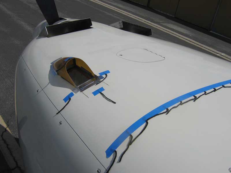
Today I made a short flight to test it. It looked pretty good, and so I glued it in. The tuft photo is a little hard to interpret because you can't get a good angle on the cowling from inside the cabin, but I could see that the tufts around the hood were steady and pointed in the right direction, and those in the row a foot behind it seemed undisturbed.
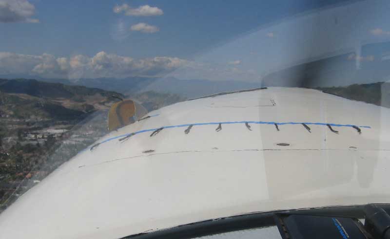
The whole setup is a violation of my general principle that inlets and outlets should be as few as possible, but it seems to have no ill effect on performance, so I guess either I got lucky or my general principle is not a sound one. Whether the hood has an ill effect on the rate of flow through the duct, and therefore on the oil temperature, I don't yet know.
[March 28, 2010]
Except for the bellmouth at the entry point, the oil cooler duct is now complete:

The baffling around the top of the duct is intended to prevent air on the downstream side of the engine from leaking into the duct. When the cowl flaps are closed, the pressure difference between the top (low pressure) side of the engine and the outside world can be much larger than the difference between the underside of the engine -- the high pressure plenum -- and the top.
[March 21, 2010]
Nancy and I went to the east coast for a week, where our daughter Lily was playing Masha in a Brown production of Three Sisters. She was terrific, by the way; I say this with complete objectivity, being notoriously inclined to overcompensate for parental bias. In the meantime our son Nick and his wife Samantha and their baby girl James were in LA, and now that we are back home I have been grandfatherly and have not been going to the airport; so nothing has happened to the airplane in the past couple of weeks. When I get back to it, later this week, I need first of all to get the baffling and fairing of the oil cooler air outlet worked out, and then to make a suitable bellmouth for the other end of the duct. Paul Lipps, who has been making a flasher controller for me, says it's almost ready, and so I guess the next task will be forming the wingtip light lenses and getting the nav and panel lights working.
I got a replacement glideslope receiver, but although the glideslope needle swings out of the way the needle doesn't move; so I guess the problem was not in the receiver after all.
[March 5, 2010]
Flew to Catalina today for lunch. Oil temperature is no longer an issue, but I have not yet made a fairing around the oil cooling air outlet and so I have not done any speed checks to find out whether this new modification has increased drag to a measurable extent. I did notice that one of my temporary duct tape baffle seals had prolapsed into the outlet. What I found most interesting today however was the impression that after landing the engine idled more smoothly at low rpm than it used to, and after shutting down I was able to turn the propeller with no more effort than at any other time. Before I changed the starter, the engine was very hard to turn over immediately after being shut down. Can it really be that the lightweight starter was exerting that much resistance?
[February 25, 2010]
Finally I have arrived at the end of a couple of tunnels. The matter of the starter has been resolved by putting the old 16-pound unit back on the engine. Now, with the help of batteries kept in tiptop shape by my battery tender, the engine cranks like mad. Sky-Tec, who made my lightweight starter, offers a special deal, a new 5-pound starter with internal clutch (to spare the engine clutch) for $250 and your old starter. Oddly enough, they did not offer to pay the $815 bill for the overhaul of my starter adapter, which their original idiotically designed starter had ruined. Eleven pounds is a lot, but I'm not sure it's worth $1,600. Maybe to the Pentagon.
On another front, I removed the duct extension that I had added to pick up oil cooler air from just behind the prop, and found that the oil runs just as cool without it. The key to a 20-25 deg. C reduction in oil temperature was, first, to pick up the oil cooling air before it had a chance to be heated by the exhaust pipes, and, second, to provide an outlet for it that was not affected by the cowl flaps. Incidentally, removing the duct extension (see Dec. 13) also had the happy effect of bringing down the temperature of the left front cylinder to where it had been before; evidently the suction from the oil cooler duct was starving it.
A tuft test of the region around the outlet revealed horrible flow; the tufts were jumping around like a bunch of dervishes. Actually, I have never seen a dervish. But anyway, I need to provide turning vanes and perhaps some sort of hood to smooth that out, and also a bellmouth at the intake end.
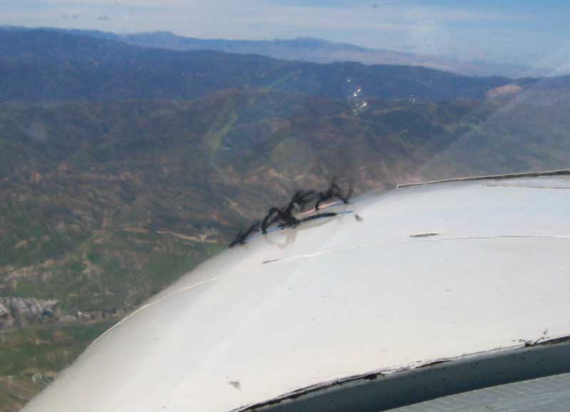
Finally, I made the mistake, when changing batteries, of failing to note the fuel quantity from the totalizer. Lacking any means to visually confirm the fuel level, I have hitherto relied on tapping on the underside of the tank; the resonance of the skin changes when there is fuel on it, and I have a graph that relates the fuel quantity to the outboard end of the fuel pool. Needless to say, this is a very approximate method. It came to me today, however -- it's incredible how long it can take for such an obvious idea to dawn -- that I could measure the fuel surface quite precisely by attaching a vinyl hose to a sump drain and noting the fuel level in the open end of the hose; my design software calculates tank volume for any pitch and roll attitude and fuel surface height. It appeared that there was 8.2 gallons in the right wing and 5.2 in the left. Using the tapping method, I had guessed 10 and 5.
[February 18, 2010]
At last the mystery of the balky starter appears to have been resolved. It seems that the first generation of the lightweight "high-torque" starters like my Sky-Tec lacked a clutch to disconnect them from the engine. The starter clutch inside the engine is a hefty coil spring that tightens around a shaft under load. The tension of the starter, which is a geared permanent magnet motor and does not turn freely when it is not energized, keeps the spring from relaxing, and eventually it wears to the point that it is no longer able to grip the shaft. The typical first symptom is exactly what happened: the prop stops at a compression peak and the starter makes a whirring sound. I removed the starter drive assembly from the engine and took it to Pacific Continental Engines, an overhauler on the field, where the guy I talked with said that if I had a Sky-Tec starter of the type whose driving nubbin cannot be turned by hand, I should throw it in the trash. This was discouraging news, but at least I still have my old starter. I then ran into Claude Morgan, who occupies the hanger two south of mine and has a Swift with a Continental 360 like mine. He turned out to be quite familiar with the problem, and said that he had put the old "18-pound starter" -- mine weighs only 16 -- back on his engine to avoid ruining the starter clutch. I am going to call Sky-Tec, whose website now makes a great point of how their current starters have electromagnetic clutches that prevent exactly what happened to me, and see whether they have a trade-in program. I'm not optimistic.
Incidentally, I was told that another cause of failures of Continental starter clutches is synthetic oil, which is so slippery that the coil spring can't get a good grip on the shaft. Lycoming engines don't have this problem (or the other one), because their starters engage by means of a small gear that pops forward to mesh with a large one. The system, called a Bendix drive, is out in the open air, unlike Continental's, which is inside the engine and bathed in oil.
Speaking of oil, I found out today that I had been right about one thing, at least: the inverted oil filter. I unscrewed it, and not a drop of oil came out.
[February 17, 2010]
I swapped my old 1970's starter motor for the Sky-Tec. It displays the same reluctance to turn over, so whatever the problem is it is probably not the starter. On the advice of Paul Lipps I checked the voltage drop all along the starter circuit with the small starter. I found nothing out of the ordinary, but since the small starter keeps whirring even when the prop is not turning, I wonder how much load it is really experiencing. Evidently its electromagnetic clutch is not engaging, and so it is never experiencing any torque to speak of. Tomorrow I will repeat the voltage drop survey with the old starter; at least when it bogs down, it stops dead.
My glideslope quit working a while ago, and I pulled the receiver, an ancient Collins GLS-350, today. It was incredibly difficult to get out, even though the instrument panels swings aside. It is held in place by a sliding shoe that is moved by a single screw; but I had put the head of that screw as nearly out of reach as it could possibly be. I'm going to arrange a better mount for it, although after this I will probably never have to remove it again.
[February 12, 2010]
I took out the batteries and worked for a couple of hours on assembling the charging socket and plug. After wiring up the part that goes inside the cowling I realized that it was going to be exposed to radiant heat from the exhaust and I could not use the wire that came with the battery tenders. I'll rewire that part on Monday. I tried cranking the engine with the mags and fuel pump off. There was very little voltage drop -- from 27 to 24 volts or so -- but that was not surprising since it was apparent that the starter motor is whirring but the prop is barely turning. I think there must be something wrong with the starter motor clutch. Bad news, if true.
[February 10, 2010]
Having built a sort of chimney on the top, that is downstream, side of the oil cooler, I reluctantly cut a hole in cowling top and made a test flight. The OAT on the ground was 19 C. The oil temperature rose to about 90 C during a climb to 8,500 feet, but then dropped to 78 C, which is the vernatherm setting, in cruise (27/2200, 141 kias, 8.4 gph). It was unaffected by my closing the cowl flaps; this was the result I was hoping to achieve. I still need to fair the edges of the hole in the cowling, provide some vanes to extract a few grams of thrust from turning the flow aft, and improve the sealing of the chimney -- I am temporarily using duct tape as a baffle seal.
The batteries were a huge disappointment, however. The starter barely turned the engine over. Actually, since it cranked equally weakly when being boosted by a Jet Center start cart at San Luis Obispo two weeks ago, the problem may not be the batteries at all. I will clean all the connections tomorrow and try it again. I had resolved to carefully watch the voltmeter during cranking to see how much drop there was under load, but then I forgot to do it. Maybe I'll remember tomorrow. I hope the problem is not the starter motor itself; that would be either expensive (buy another one) or heavy (install the gigantic original starter from 1970-something).
[February 3, 2010]
I've learned one or two things about batteries in the last few days. A couple of the important ones are that you don't replenish low fluid in a lead-acid battery with battery acid -- heck, it seemed so natural! -- and that a battery that sits unused for long periods needs to be on a continuous low charge to prevent accumulation of lead sulfate on its plates. A reader of this every-lengthening account, Glenn Stone, acquainted me with the notion of a "battery tender," which is a sort of trickle charger with the brains to maintain a "float" voltage just high enough to prevent sulfation and low enough to avoid eroding the plates. I bought a couple of them at Walmart ($20 bucks each, brand name Schumacher, look pretty solid) and hooked them up to my batteries yesterday, and today a couple of nice green lights indicate that the batteries are fully charged. I temporarily disconnected the tenders and measured the voltage at 26.6. I don't know if that's what it should be, but it seems high enough; it is slightly above the natural potential of 12 lead-acid cells, which would be around 25.2 to 25.6, and I suppose that it would drop rather quickly. I am going to install a socket in the bottom of the cowling to allow easy connecting and disconnecting of the tenders. The reason I needed two of them, if it's not obvious, is that I have two 12-volt batteries connected in series. They do not necessarily discharge and charge exactly equally, and in any case while 12-volt battery tenders are easily acquired, 24-volt ones appear, not surprisingly, to be rarer and more expensive.
[January 31, 2010]
The engine barely started for the SBP trip; in fact I had to get a fellow to come over and put away my homemade start cart and lock the hangar for me. Pleasant flight to SBP, the mountains unusually snowy after the previous week's storms.
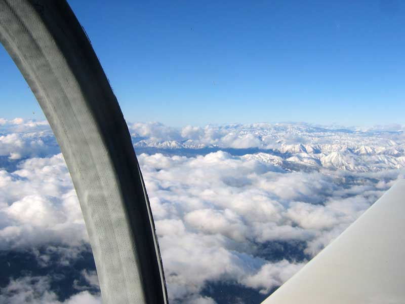
The following morning my host, Kurt Colvin, who teaches engineering at Cal Poly and owns a Husky, and I found my wings heavily encrusted with frost. That took a while to go away, and then, of course, the engine would scarcely turn over; cold is no friend to batteries. Kurt tried without success to hand-prop it, and finally a start cart had to come over from the Jet Center. The engine should have whirled like a top, but it still cranked only weakly; it did start, however. On getting home and inspecting the batteries I found them to be heavily sulfated. In the course of acquiring new ones -- I use two 20-a.h. Yuasa motorcycle batteries in series -- and reading up on how to charge them, I learned that I have not been doing my batteries a favor for all these years by replenishing them with battery acid rather than distilled water; that just accelerates the sulfation by increasing the concentration of sulfuric acid, which apparently evaporates more slowly than the water. It is also advisable, it seems, to keep them on a "float" charger -- a steady 50-100 mA -- during periods of disuse. It is humbling to discover that I am still ignorant of such elementary things.
[January 19, 2010]
While rummaging through photographs to use as part of a presentation I'm giving to an EAA chapter in San Luis Obispo this coming weekend, I came upon this shot of an early, and abortive, project of mine called Tern, which is briefly described in the portion of this website devoted to the earlier Melmoth.
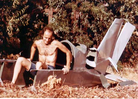
The paths of glory lead but to the grave.
A couple of people have suggested punching a hole in the oil filter a few minutes before unscrewing it to ensure that all the oil in it drains out. I was assuming that since the filter is above the engine and the circuit is open to the air through the crankcase, that would not be necessary; but maybe it will. If so, I will have to do it with something other than the recommended centerpunch, since the firewall, which is made of a ceramic/carbon/nomex sandwich and is very light, is not intended to withstand hammer blows.
I have been working on a design for a four-seat single-engine jet, a project originated by Austin Meyer of X-Plane fame, who apparently wishes to put to the test the adage that the way to make a small fortune in aviation is to begin with a large one. Here is what my design looks like; the rainbow colors represent pressures on the airplane surface, the red end of the spectrum being low pressure and the blue end high:
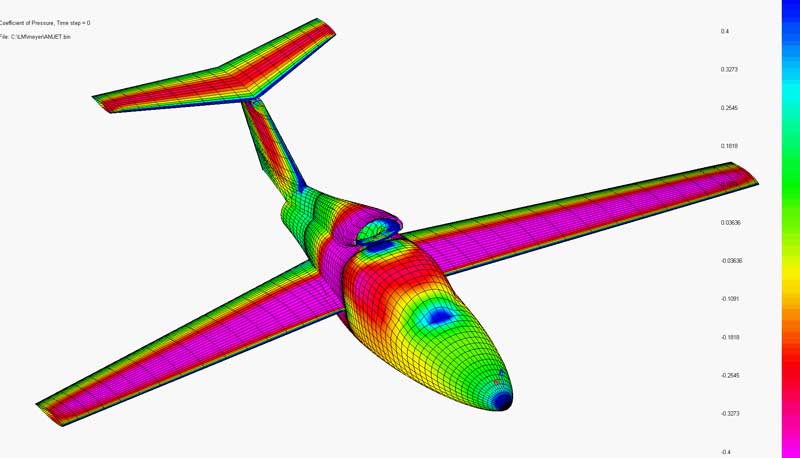
[January 13, 2010]
In accordance with my policy of veering off from time to time into some irrelevant activity, I removed the oil filter from its position on the right side of the nosewheel well/engine mount and put it on the firewall. Viz:
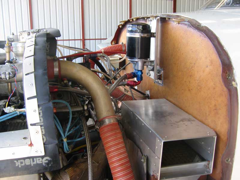
The idea was mainly to make it easier to get at, but also to see whether putting it into an inverted position would make it easier to change the filter without having to take elaborate precautions to avoid spilling oil all over the place. An inverted filter drains into the engine when it is shut down, except for oil that is below the top of the screw-on spigot; that, however, is supposed to be retained by a rubber flap around the perimeter of the filter. So in theory you should be able to remove the filter without any oil escaping from it at all. We'll see. Inverted filters are used on some cars, for instance MG-Bs (not much of a recommendation) and some Ferraris (hardly more). They are suspect in MGs because of the delay in developing oil pressure on startup; but in the airplane that should not be a problem, because oil does not even flow to the filter until the vernatherm valve opens. Since that happens gradually, I think the air in the filter should enter the engine in a fine stream of bubbles without affecting the lubrication. I made one circuit today to check for leaks. Everything seemed normal. I had moved the thermocouple (see below) to the top plug on the right middle cylinder; there it registered about 50 deg F higher than on the bottom, which is expected. I also looked at the bubble catchers in the flap hydraulics; nice and dry, and no air to speak of inside.
Paul Lamar, who is a guru of the rotary-engine community, said in one of his communications the other day that every 90-degree fitting in the oil plumbing raises the oil temperature, and that removing one could bring the oil temperature down 10 to 20 degrees. I have four of them. I don't understand, however, how they can affect the oil temperature, since the lubrication system is positive-displacement. They may raise the oil pressure a little, but I don't understand why they would have a detectable effect on temperature.
[January 7, 2010]
I've made a couple of flights now with the spark plug thermocouple; it seems to match up pretty well with the description in the previous entry, but I'm still not persuaded that temperature readings from a bayonet thermocouple should really be interpreted as being incorrect when cooling is updraft. I discussed this yesterday with Mike Melvill, who has updraft cooling in his Long-EZ. He observed that the tip of the bayonet, which is quite long, is buried deep within the cylinder head, close to the cylinder wall, and it is hard to imagine that blowing cool air on the other end of it could have much effect on its reading. That is my impression as well. We also agreed about the heat load in the cylinders being concentrated on their undersides -- see the previous entry. If the bayonet thermocouple reads low, perhaps it simply means that the hottest part of the cylinder is cooling better -- which would be a good thing, not a bad one. I wish I could find some serious technical analysis of this topic, rather than hand-me-down guidance in online discussion groups.
The last leak that I fixed on the flaps has had a remarkable effect. It didn't seem to be that bad a leak, but since I fixed it I have not yet had to add hydraulic fluid anywhere, and the flaps have been staying in synch with one another and extending fully at each use. It's too early to declare victory, especially since I haven't looked under the seats lately, but I'm encouraged.
[December 29, 2009]
The holidays have been a time of complete inactivity on the airplane front. However, Dick Eklund, who handles plans sales and support for the Thorp T-18, has sent me a couple of spark plug termocouples and a calibrated CHT gauge. With its help I hope to get some idea of the relation between the CHT as indicated by the bayonet probes, which are on the lower and therefore colder sides of the cylinder heads, and the factory CHT recommendation, which assumes downdraft cooling. I came across one plausible-sounding discussion of this topic on a Cozy site; here it is, slightly amended and amplified by me:
Lycoming says that cylinder head temperatures should never exceed 500 deg.F (260 C), but for maximum service life, cylinder head temperatures should be maintained below 435 deg.F (224 C) during high performance cruise, and below 400 deg.F (204 C) during economy cruise. High performance cruise is 75% power and 150 deg.F on the rich side of peak EGT. Economy cruise is less than 75% power and leaned to just above roughness. These temperature limits assume downdraft cooling and temperatures measured at the bayonet location under the cylinder, which is the hottest side with downdraft cooling. For updraft cooling you need to correct for the temperature difference across the cylinder, so add 40 deg.F (22 C) to the reading in climb and up to 70 deg.F (39 C) when leaned in cruise. If you are measuring CHTs with thermocouples under the bottom plugs, the temperatures are approximately correct without correction. If you are measuring CHTs with thermocouples under the top plugs, subtract 40 deg.F (22 C) from your readings to make them comparable to bayonet readings on the hottest side of the cylinder. So if you are using bayonet sensors on the bottom of the cylinders, your indicated temperatures should range from 300 deg.F (150 C) to 350 deg.F (175 C). Continental's recommended temperature for a bayonet thermocouple with downdraft cooling is 370 F (188 C); this would roughly correspond to 150 C for updraft cooling.
If, as I hope, this information is correct, it would suggest that I have been running 20-30 C hotter in economy cruise than I think I have. Unfortunately, the weasel words "up to 70 deg.F" leave room for doubt, and it is not clear why there should be different corrections for climb and for cruise. The matter is complicated by the fact that the bottoms of the cylinders, which with downdraft cooling would experience the greatest heat stress because the exhaust outlets are there and are provided with very little finning, would presumably be better cooled by updraft flow, while the tops of the cylinders, which have lots of fins but less concentrated heat, might receive less cooling but also need less. One might suppose that the temperature difference between tops and bottoms would be smaller with updraft cooling; the thermocouple readings from the top and bottom of a cylinder should shed some light on that. In the meantime, I can easily bring the CHTs down by opening the cowl flaps a little; that also reduces the oil temperature by a few degrees.
[December 14, 2009]
Finally, a palpable result. OT initially sat at about 80 C, then crept slowly to 85. This was with cowl flap open, that is, a decent delta-p (pressure drop) across the cooler. When I closed the cowl flaps the temperature went up to 88. Unfortunately, since I violated a basic rule of experimentation by making two changes at once (extending the duct intake to guaranteed cool air, and lagging the exhaust pipe near the duct) I do not know to what I owe the improvement. But the sensitivity to delta-p inclines me to think that it would be a good idea to provide the oil cooling air with a separate exit. For some reason, the temperature probe did not work on this flight, and so I could not confirm the temperature of the air within the duct.
[December 13, 2009]
On Friday I extended the oil cooler intake duct to a position just within the nose air inlet with the idea of picking up air before the engine gets a chance to heat it. I tried this before, but with such a tortuous duct that I was not sure that temperature gains were not being erased by duct losses. Anyway, in the next day or two I'll fly with this setup. The temperature probe is inside the duct; its lead is taped to the surface of the duct. I lagged the portion of the exhaust manifold that passes close by the oil cooler on the chance that a significant amount of heat is being radiated into the duct walls from the pipe. Here's the present setup:
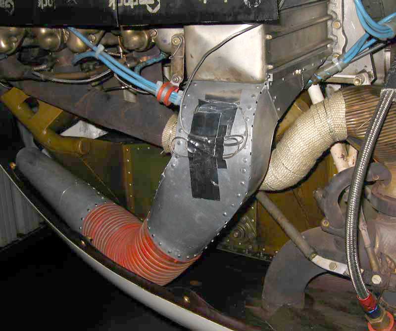
You wouldn't guess it from the picture, but the cross-sectional area of the mouth of the duct is about 25% greater than that of the SCAT hose.
[December 9, 2009]
Yesterday I flew with the temperature probe in the oil cooler inlet duct. The temperature there was 34 C, the same as I measured behind the engine in the high-pressure plenum. The OAT was 10, so a considerable amount of heating of the cooling air is taking place before it actually gets to do any cooling. This may have to do with the location of the main air inlet just behind the propeller and below the spinner. It obliges air to flow around the oil sump and through an obstacle course of exhaust pipes and whatnot before getting to the cylinders and oil cooler. I have toyed with the idea of replacing the medial inlet with two inlets placed low on the cowling and some distance away from the propeller, something like this, but less ugly (that this is a T-34C, and the temperature was 34 C, moves me to think, annuit coeptis):
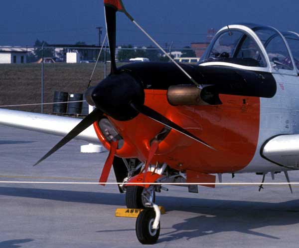
Such an inlet might improve the cooling air flow path. Despite the preheating of the cooling air, however, the cylinder head temps on this flight were about 150 C with the cowl flaps completely closed. CHT is not a problem.
[December 3, 2009]
Sifting through some old slides of Melmoth 1, I came upon a picture of the instrument panel that I think may have been taken while en route from Key West to Cozumel in the summer of 1974. It is interesting to compare it with a picture of the panel of Melmoth 2, taken in June, 2007 en route from Paso Robles to Los Angeles. Many of the instruments are the same, so it's easy to compare their readings.
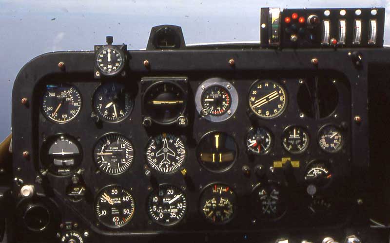
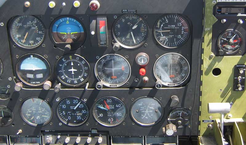
First, performance. M1 -- this was early in its career -- was indicating 144 knots at 6,500 feet at 21.5/2500, that is, 161 ktas at maybe 70% power and a surprisingly rich mixture. The fuel flow is probably around 9.5 gph. M2, cruising at 11.500 feet at 26/2200 and lean of peak EGT, is indicating 141 knots, for a true airspeed of 169 knots at 8.8 gph (that's the fuel flow/totalizer at the upper right corner). This confirms my general observation that M2 is slightly faster and more efficient, despite being a four-seater; the big difference is its wingspan, which is over 35 feet to M1's 23. M1's cylinder head temps are at or above 200 C; M2's are 160 and 190, the 190 being the right rear (#1) cylinder, surprisingly enough after I figured out why it was running hot. I now cruise at between 150 and 180 C; but M1's oil temperature is about 65 C, whereas M2's is 100. The big difference in power settings is due to M2's being turbocharged and M1's having been naturally aspirated at the time the picture was taken. The manifold pressure gauge, by the way, is the same in both photos. It is a twin-engine gauge, and at some point I had the needles painted red and blue. The blue needle (needle #1 in 1974) is static pressure; it serves as a backup altimeter if you read it backwards from 30. The red needle (#2) is the manifold pressure.
[December 2, 2009]
Finally back to the hangar after a couple of weeks of holiday cooking and hanging out with our son and his wife and now seven-month-old daughter. I took out the #1 bubble catcher, which was still leaking hydraulic fluid, chased the threads, and potted an AN fitting into it with JB Weld. That should work. I then made a flight to check oil temperature with the duct as it appears in the photo below -- no hose, no bellmouth, just a way of getting at air that has not been playing footsie with the exhaust pipes. The result was not too promising: still 100 degrees C, even though the OAT was 13. I'll put the temperature probe inside the duct next.
[November 14, 2009]
A morning both eventful and unsatisfactory. I got out to the airport at 6:20 a.m. and attached the duct to the oil cooler. I didn't want to cut an expensive piece of 3.5" SCAT until I knew exactly how much I'd need, so I crammed about 40 inches of the stuff into the cowling and tied it down with safety wire. The front end is about 10 inches behind the air inlet. I then took off to test the cooler. There ensued another one of those educational glitch-parades that make test flying so amusing. The cable connecting the flap handle to the flap valve jumped its track when I was putting the flap handle back into the neutral position after setting the flaps for takeoff, but I was unaware of it. When I went to retract the flaps, the flap handle jammed, with the result that the hydraulic pump ran continuously. I had to pull a breaker to stop it. But rather than retract, the flaps went to the landing position, because the valve was not following instructions from the handle. So I flew around the pattern at 80 knots, got the gear down by briefly resetting the breaker, and taxied back to the hangar. The problem was easily corrected, and I re-tensioned the cable so that it would not misbehave again, at least not immediately. I then went out to fly again. This time the left flap, which is always the troublesome one, did not extend symmetrically, so I left the flaps up and took off. Disappointingly, the oil temperature went up to about 90 C. This is better than it was, but it was a chilly morning, at least by LA standards, and it's hard to separate the effects of cooler ambient air from those of the duct. I had of course been hoping that the temperature would go to the factory-recommended 77 C and stay there. So now the question is whether the long, somewhat tortuous duct is impeding the flow, or the lack of large improvement is due to about ten other possibilities I can think of.
One observation I made that was of interest (to me, at least) was that the temperature behind the engine, on the "cold" side of the baffles, was around 40 C -- that is, quite a lot lower than the temperature at the inlet to the oil cooler. So the oil cooler seems to be getting a specially heated stream of air; this may help explain why the oil temperature is high, but the cylinder head temperatures aren't.
[November 13, 2009]
I got the oil cooler duct done just too late to add a bit of SCAT hose going to the air inlet and make a test flight. I hope to do it over the weekend. The duct is entirely flush-riveted, with the flush heads inside.
It will be interesting to see how this affects the oil temperature and also how the oil temperature is affected by the cowl flap position. I suppose that ideally the oil cooler would have its own air outlet, so that it experienced maximum delta-p at all times. On the other hand, you don't want to be putting more air through the cooler than it needs. The engine temperature is regulated by the vernatherm valve, which controls the flow of oil to the cooler. In principle you would like the vernatherm to be fully open when the oil temperature is at the recommended 170 deg. F; that would mean that the amount of oil cooling available is exactly the amount needed, and no extra air is being sent through the oil cooler. But I am getting ahead of myself. The first thing to find out is whether the duct brings the oil temperature down or not.
[November 10, 2009]
I am once again indebted to my alert Swedish correspondent, Jan Carlsson, who continues thinking after I stop, for pointing out that it is not impossible, as I said yesterday, that the static pressure in the plenum be greater than q. The source of the extra pressure would be the propeller. Duh.
[November 9, 2009]
On Sunday Hans Kandlbauer and I collected another batch of cowl pressure data. We had generally smooth air, which is needed because the water manometer is very sensitive to little jiggles. Nevertheless, some of the results were suspect; the pressure in the bottom plenum was a little higher than q at low speeds, which is impossible. For what it's worth, however, here is the variation of delta p, the pressure drop across the engine, at a range of cowl flap positions and airspeeds. There is some scatter in the data, especially at 100 knots.
The cowl flap position values are the size of the opening at the aft edge of the flap. Because of the deformation of the cowling under pressure and the placement of the limit microswitch, the flaps stop slightly short of fully closed. At 140 kias, zero is really 0.25; at 80 kias, it is more like 0.15. The line colors are indicated airspeed in knots. It is interesting to note that the last half-inch of travel, between the "climb" position (1.5) and the "ground cool-down" position (2), yields barely any gain. Otherwise, however, the variation of delta p with respect to outlet area is pretty linear. The outlet area at 1.5 is about 60 sq. in., which is approximately equal to the inlet area.
[November 5, 2009]
There's supposed to be a guy at the airport who has an oven with provisions for vacuum-forming plastic lenses. I go by his hangar every day, but he never seems to be there. In the meantime, I've gotten interested in the oil temperature question and am making a duct, as suggested by Jan Carlsson, to pick up cool air before it has had a chance to flow over the exhaust pipes. Every once in a while I treat myself to a little nostalgic metal work -- my first airplane was all-metal -- and I remember how much fun it is. Sheet aluminum is like a child: It doesn't want to do what you want it to do, so you have to trick it or compromise with it. (Some people beat on it, but I am of the nonviolent generation.) Here is the duct after a few hours of work:
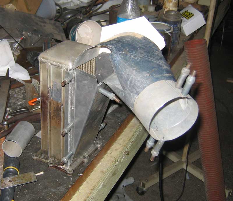
That's a spare oil cooler -- I didn't have to take it off the engine. The entry to the wedge diffuser below the cooler is 10 square inches -- a wild guess -- and I just happened to have some 3.5-inch SCAT, which is the same size. The duct bends down 90 degrees and forward 30, while transitioning from a 3.5-inch circle to a 4 x 2.5-inch rectangle.
While measuring the temperature of the air entering the oil cooler last week, I took a few pictures of tufts on the rear window. There is some slight unsteadiness along the centerline at the extreme aft end of the canopy, but the view is probably worth it, since the rear seats face aft. Yes, the upholstery of the pilot's seat is still a pillowcase.
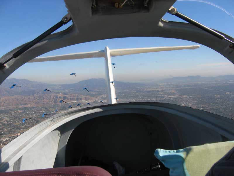
[October 30, 2009]
After my last posting I received an e-mail from Jan Carlsson of JC Propeller Design in Sweden, suggesting that the reason for my high oil temperature was that the exhaust pipes were preheating the air going into the oil cooler. I didn't believe that this could be the case, since the cylinder head temperatures are quite low, and they would be under the same influence. Today I measured the temperature at the entrance to the oil cooler, and found that I was wrong and he was right; the temperature was in the neighborhood of 60-65 C, or around 150 F. Small wonder the oil is hot. Jan suggests a duct from the air inlet to the oil cooler; another possibility would be a separate air inlet on the cowling side, which would make quite a crowd of inlets, since the induction air NACA scoop is there already. A third possibility would be an insulated plenum built into the bottom of the cowling, fed from the front inlet, supplying both the oil cooler and the induction and supplanting the NACA induction-air inlet. I'll think about this for a while. I also need to repeat the test, and measure the temperature of the air emerging from the cooler, to be sure that I am separating radiant from convective components properly.
The gadget with which I measured the temperature, by the way, I got at Radio Shack in November, 2003. It's intended for letting you know when the meat on your barbecue is ready, and consists of a probe, a transmitter, and a remote receiver that displays temperature. It cost about $25.
[October 28, 2009]
On Sunday Hans Kandlbauer and I collected cowl pressure data using a water manometer with two circuits, one comparing the high- and low-pressure plena (this is "delta-p", the pressure drop across the engine), the other low-pressure (as I thought) and static. The results looked pretty nonsensical until I realized that the low-pressure vs. static data were really high-pressure vs static. Then they made sense, but just to be sure I'm going to run the tests again. The confusion was due to the ambiguous labeling of some pressure hoses I had installed years ago; "low" could mean low pressure or low (that is, below the engine) plenum; obviously, in an updraft system the physically lower plenum has the higher air pressure.
The aim of all this data gathering is to understand why the oil temperature is higher than expected. It runs between 90 and 110 deg. C, depending on OAT (Southern California tends to be way above standard almost all year long) and cowl flap position. The factory recommendation is 170 F, or 77 C. The oil cooler is part of the engine, and the whole arrangement is the same as it was on Melmoth 1, except that the air flow is in the opposite direction and the length of the hoses going from the engine to the oil filter is greater (an extra three feet or so of 1/2 inch tubing). The filter is of concern because I have installed a diverter between the engine and the oil cooler; oil heading for the cooler gets sent through the filter first. The filter is a few inches away from an exhaust pipe, and I suppose that some radiant heating must be taking place, but certainly not enough to account for the observed temperature increment. The oil pressure runs about 45 psi in cruise, and since the oil pump is a positive-displacement device there is no reason to think that the impedance of the plumbing and the filter itself (which is a Bosch automotive model) is responsible. Just to make sure, I intend to short-circuit the diverter, bypassing the filter. I will also calibrate the oil temperature probe, though I have done this before and have no reason to suppose that its behavior has changed.
On Melmoth 1, the oil temperature maintained the factory Vernatherm setting of 170 F. One possible explanation for the difference now is that because the CHT probes are on the bottoms of the cylinder heads, they indicate cooler, for a given overall heat content in the cylinder head, than they would with downdraft cooling. That would imply that I should be aiming for CHTs lower than the recommended 370 F, which would mean a larger cowl flap opening, which would mean higher delta-p. It's evident that the minimum cowl flap opening of 18 square inches, which I normally use when cruising, results in a buildup of pressure above the engine and a consequent drop in delta-p; at 140 kias with the cowl flaps closed, we measured a delta-p of just four inches of water, which is less than a third of the total pressure. But even with the cowl flaps open and the CHTs abnormally low, the oil temperature never drops to 170 F.
[October 22, 2009]
Today I finally managed to record the tuft test of flow attachment on the stabilizer during the landing. CG was about as far forward as it gets, with full flap and no airbrake (the airbrake produces a nose-up pitching moment, and so it reduces the tail load). The video is short and somewhat difficult to interpret. It begins as the airplane crosses the airport boundary; the trimmed elevator angle is about -5 degrees. The approach speed is too high and so the flare goes on for some time; you can see the stabilizer hunting farther and farther upward, beginning about 9 seconds in. The landing itself is not detectable on the tape; but at 17 seconds the elevator suddenly deflects fully upward. At that point, the main wheels are already on the ground and I am holding the nosewheel off. When the elevator is fully deflected, the flow on it is separated; but there is practically no flow reversal while the plane is airborne.
[October 21, 2009]
Several people wrote to suggest that the low airspeed reading on landing might be due to a particularly steep pitch attitude -- that is, to pitot, not static error. But with full flap the pitch attitude on landing is actually quite flat, so I don't think that's it. This weekend I am planning to do some landings while someone in the right seat watches the GPS. I'm not certain this will tell me much, however, since the apparent position error is in the range of 3-5 knots, and uncertainty about the wind could be in that range as well. We'll see. I have also hooked up the little camera that I mounted on the tail a while ago; it is looking up at the horizontal tail, which I have tufted in order to see whether the elevator flow is separating during the landing flare. Another task in this little set of tests will be to record pressures in the cowling at various speeds and cowl flap settings, using a water manometer.
I have also made the male tool for the wingtip lenses, and yesterday I laid up a couple of plies of glass over it in order to make temporary covers for the holes in the leading edges where the lights will eventually be. These covers will also serve, later, as templates for trimming the plexiglas lenses. The actual mold for the lenses will be a plaster female, and I hope to draw the heated plexiglas into it with a slight vacuum.
[October 9, 2009]
I had some e-mail discussion this morning with John Roncz regarding the landing speed of 48 kias. We agreed that it is implausibly low, implying a CL for the complete airplane of more than 2.6. John said he would have expected something closer to 2.2-2.3, which would give a stalling speed of around 53 knots. So the question is, why is the indication so low? One explanation would be position error; but a position error of 5 knots would require a high, and unlikely, positive pressure at the static ports. I then ran a Cmarc analysis of the airplane, flaps down, in and out of ground effect. At an angle of attack of six degrees, the predicted CL for the complete airplane was 2.17; in ground effect, at the same angle of attack, it was 2.54. This difference pretty closely corresponds to the disparity between the expected and the observed stalling speeds, but this may be mere coincidence, since I am not sure that a wing should be expected to stall at exactly the same angle of attack in and out of ground effect. Since Cmarc predicts CL but not the stall itself, these analyses may or may not have much relevance to the question; but they do suggest that an airplane might possibly touch down at a speed somewhat lower than its stalling speed out of ground effect.
Incidentally, at Melmoth 2's wing loading of about 20 pounds per square foot and at landing CLs in the vicinity of 2.0, a change of 0.1 in the maximum lift coefficient produces a change of one knot in the stalling speed. The landing rollout is proportional to the square of the speed at touchdown, and so each added knot of landing speed represents a change of about four percent in the landing distance. If the braking distance is 500 feet with a touchdown speed of 50 knots, it will be 600 feet for 55 knots. The extra 100 feet would be covered in about 1.3 seconds during the flare. That is why speed control during the approach is so important for maximum performance landings -- more important, usually, than small differences in maximum lift coefficient.
[October 8, 2009]
Finally, I managed to shoot some tape of the flap with tufts.
A video of one circuit around the pattern at Whiteman is on YouTube. Unfortunately, in order to get as much of the flap as possible into the frame I was obliged to tilt the camera about 40 degrees. This test was flown at 2,200 pounds, with 100 pounds of ballast in the baggage compartment in order to be able to trim hands-off at approach speed, or anyway what the Safe Flight angle of attack device thinks is approach speed (about 73 knots with full flap; 1.3 Vs would be more like 65). All tufts are attached and steady during takeoff and climb. When the flap is retracted, a large area of unsteady or reversed flow appears near the trailing edge of the wing. I have discussed this earlier (3/17/09); it is probably due to the thickness of the laminar airfoil, which is 18% out to BL 48. The outboard set of tufts, which are at about BL 125, are in better shape; the thickness there is more like 15%. It is unlikely that a wing root fairing would have any effect on this separation; the tufts at the bottom of the frame are at BL 48, and the side of the fuselage is at BL 25. Accelerating to about 100 kias, which is five knots above the theoretical speed for best rate of climb, removes most of the unsteadiness.
The flow attachment with full flap is just about perfect right down to touchdown, except in the wake of the middle track. This is not especially surprising, since the maximum deflection is only 30 degrees with respect to the wing chord line; if it were 40 degrees, there might be more separation. Around the middle track, the flow is attached over the front portion of the airfoil, so it is generating some lift, but completely separated over the aft portion. The reason the disturbance seems to be located mainly on the inboard side of the track is that the rear spar has forward sweep, and the flap track is at a right angle to it. It is therefore angled outward with respect to the air stream.
Touchdown occurs, as I noted yesterday with condign skepticism, at an indicated 48 knots.
[October 7, 2009]
Yesterday I tufted the left wing and flap and set up a video camera to record some takeoffs and landings. I put 50 pounds of ballast into the baggage compartment in order to make it possible to trim to approach speed with full flap. Today I flew to Santa Paula, bought 40 gallons of fuel, and flew back, reaching back over my left shoulder to turn the camera on and off. Unfortunately, I couldn't see the monitor, and upon inspecting the tape at Whiteman I discovered that I had recorded, in all, approximately three seconds in cruise somewhere over the Santa Clarita valley. I'll try again tomorrow. I did observe 48 knots just before touching down at Whiteman. I suspect position error, because that would imply a CL of 2.6. Doting father though I am, I cannot imagine that my flap is performing quite that well.
[October 2, 2009]
Flew Wednesday and today, staying in the pattern, trying to refine my landings with flap. It's apparent that even at 70 kias I'm still carrying too much speed on final; the plane floats quite a bit after I flare, even with the airbrake open. (On one touch and go I failed to retract the airbrake; it cut into the climb rate, but not dangerously. The main tipoff was buffetting due to separated flow in the wake of the brake.) The problem is that when I am flying alone the CG is so far forward that I can't trim for the proper approach speed. I think next week I will put some ballast into the baggage compartment in order to get the CG to a more natural position.
The flaps are working well, although they still do not extend fully; they stop about half an inch short of the end of the track. This is due to air still trapped in the hydraulic system; I expect that it will disappear over time, because some of it will get entrained as foam during each cycle and will end up in the bubble catchers. It appears that the flaps take 13-15 knots off the landing speed. The clean power-off stalling speed was 68 knots during initial flight test; the 200-pound weight gain since 2002 would increase that by about 5%, or 3 knots, at 2,000 pounds. (Today the airplane weighed about 1,900 pounds.) It now seems to touch down at around 50 or 51. The additional weight has also taken a bite out of the initial climb rate. Back when I could fly at 1,750 pounds or less and used 40 in. Hg. for takeoff, the initial climb was 2,000 fpm or more; now I use just 34 inches and with the added weight see only about 1,500 fpm.
It has been suggested that the intermittent problem with the push-to-talk switch could be temperature related, since it tends to occur initially and then correct itself after some time has passed. That might point to the audio panel, since it is the only thing in the mic key circuit that changes temperature.
[September 28, 2009]
Tried to fly today, not having done so for almost seven weeks. First, the batteries were low and wouldn't turn the engine over. I started it with the help of my ground cart, which consists of a homemade creeper with a couple of ancient auto batteries on it. Under normal circumstances they have a combined voltage of 8.7, but if I connect my homemade charger to them -- the Oneirodyne Amazo-Charge, as my old friend Peter Christie would have said -- they start the plane right up. And did. I taxied out, only to find that the mic key again (this last happened at Santa Fe in June) would not key the transmitter. Frustrated, I returned to the hangar and, just to have done something useful, checked the #2 flap master cylinder, which I re-sealed last week, for signs of leakage. There were none. I then gave the mic key one last try. People like to say that the definition of insanity is doing something over and over and expecting a different result, but this is quite false, and in fact in this case the result was different-- the XMIT light on the radio came on. By this time it was getting late and the plane was already back in the hangar, so, to paraphrase Lillian Roth, I'll fly tomorrow.
I really need to find the solution to this mic key problem. It is not the key switch -- which is on the sidestick -- itself; the problem remains even if I insert a manual key in the headphone mic line. It always seems to occur after startup, not during the course of a flight, and it resolves itself spontaneously sooner or later. It is as if an electrical bubble had gotten caught in one of the wires -- but there is no such thing as an electrical bubble.
My reading about Kelly Johnson and the Skunk Works has reminded me that many of the most satisfying days of my life have been spent on my airplanes, working from handwritten notes or scribbled sketches, and using the airplane itself as a mockup -- all techniques espoused by Johnson in contrast to the highly systematic and formal ones customary in aerospace. He tried to replace the drudgery of the factory floor with the excitment of the home workshop, and the oppression of the group with the passion of the individual.
[September 22, 2009]
There was nothing very mysterious about the leak in the #2 flap master cylinder, as it turned out; the static O-ring that seals the two parts of the cylinder when you screw them together was torn nearly in half in not one but two places. Oddly, it looked fine in its groove when I opened up the cylinder, and even after I removed it. It wasn't until I twisted the ring 90 degrees out of its natural set that the rip suddenly appeared. The damage must have happened during assembly. A new O-ring cost $1.35; some airplane parts are cheap. I wasn't sure how to lubricate it for re-assembly, but finally decided to leave the groove dry and to grease the inner faying surface thoroughly. I'm not sure that made sense; time will tell. Everything worked fine when I put it back together, but it will take a few cycles to know for sure.
[September 18, 2009]
I got back to the airport today for the first time since returning from the East on Tuesday. The hangar was as changeless as an Egyptian tomb. I hesitated to take the flap synchronizer apart in order to repair the leaks, since I expect to need to use the airplane next week, and I am very busy researching an article on Kelly Johnson, of Lockheed Skunk Works fame, for the Smithsonian's Air & Space magazine. I finally decided to go ahead, and managed, in the course of three hours, to repair the small fifth cylinder whose job is to restore everything to proper alignment after each flap retraction. The inside of the cylinder was badly scored, I'm not certain why, but it may have been galling between the aluminum piston and the aluminum cylinder. I ended up replacing the tube -- twice, actually, since I hastily drilled some holes in the wrong places the first time around. That's par for the course for me. I hope the #2 master cylinder, which drips, will be easier to fix; I suspect it's just a matter of a twisted or damaged O-ring, or some crud that got under the O-ring in my negative clean room.
[September 4, 2009]
We are staying in a friend's house at the mouth of the Pamet, a pygmy river that rises a stone's throw from the Atlantic near the tip of Cape Cod and flows three miles westward into Massachusetts Bay. Each evening Nancy and I go down to the harbor a little before the sun sets, walk some distance up the Pamet, and then turn as the sun vanishes below a small dune and walk back, stopping to admire the seabirds feeding in the slack tide and the ineffable mother-of-pearl palette of cloud, sky and water. We come here every year, and every year before coming I make a mental list of the things I am going to accomplish while here -- new or improved features in my computer software, a chapter in a never-finished book about the first Melmoth, the missing 20 percent of a film script that I wrote several years ago and that concerns, strangely enough, a pilot -- it's sort of Shane meets Medea, with wings. Each year, I do none of these things, falling, instead, into a daily cycle of shopping, cooking, reading, making minor house repairs and going to the beach, a routine that somehow swells to occupy every second of the time. This evening from our vantage point along the river we could see our son on the distant stone breakwater, casting for blues, a tiny erect figure against the twilit sea. He had waded across the harbor to get there, and probably underestimates the difficulty of returning in darkness, which is gathering as I write this. But he is a resourceful fellow, and will be back in time for dinner. He would not miss a lobster risotto.
[August 20, 2009]
I'm going away Saturday night for three weeks on the east coast, and leaving the plane here; so there will be a slack period in this otherwise gut-wrenching narrative. Because of having a lot of writing to do before leaving, I have not been at the hangar as much as usual; so I went there today to secure a few things, put tools away, and have a last (for a while) look at the plane. I did a little wiring, just to feel that I had accomplished something, and made a list of things that will need to be taken care of when I return, including the hydraulic leaks, the obligatory bi-annual static certification, and the glideslope receiver, which has stopped working. And, of course, I must figure out how to make lenses for the wingtip lights, and build the flasher circuit that Paul Lipps designed. At the rate I go, all this should take me well into November.
[August 14, 2009]
The #2 flap master cylinder is leaking again, as is the mysterious "driver" cylinder that is responsible for getting everything back into alignment at the end of each flap cycle (see diagram at October 13, 2008). For that matter, the airbrake cylinder has been leaking for a while too, so I have a bit of maintenance to catch up on. I don't remember the first Melmoth being quite so hydraulically incontinent as this, but I continue to believe that once I find and correct the cause of every leak, the system will cease to require much maintenance. At present, three of the four master cylinders are bone-dry, as are both inboard flap actuators and possibly the left outboard one as well. None of the connections in the plumbing is leaking any more, and not a single nylon line has blown out in the past two or three weeks -- this must be some sort of record. The right outboard actuator still seems to leak a bit. I tentatively attribute the proneness of the outboard cylinders to leak to their being subject to side loads, although I provided quite a lot of lateral slop where they connect to the flaps. Well, not for nothing does the airplane have "EXPERIMENTAL" written on the side of it.
[August 8, 2009]
Yesterday I took our daughter Lily up in the plane; she was the last remaining family member who had not flown in it. We moseyed around the west end of the San Fernando Valley at 4,500 feet, crossed the Santa Monica Mountains to Malibu, circled over the ocean and retraced our steps. I was in a quandary as to whether to tell Nancy before we did this, and decided not to. There was no good solution; she was going to be unhappy about it either way. I didn't, and she was, but we got back alive, so there wasn't too much to complain about. Lily liked it, and started talking about family trips to Baja -- "as soon as the drug war is over."
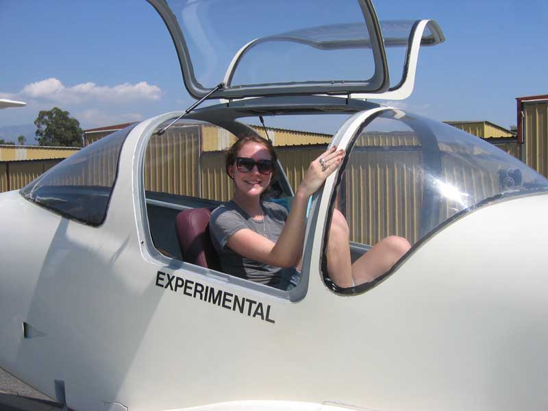
I saw the South African guys on Thursday, a few hours before they took off for Hawaii. They made it in 21 hours. Nice chaps. They are going to be over water practically the entire remainder of their return to SA, but they have only one more leg left that's as long as the LA-Maui one.
[August 2, 2009]
I got the bulbs from a downtown warehouse operation that didn't even have a sign outside, although it has a brightly-colored web presence. It was fun, something like venturing into a Moroccan souk. But I didn't work much on the plane last week because I was writing an article about Steve Fossett's accident and also fixing bugs in Loftsman that John Roncz uncovered in the course of designing an oddly shaped little aircraft. I finished the wingtip light assemblies and barely began making the tooling for forming the acrylic lenses for them.
On Wednesday I'm supposed to go down to Torrance to chat with a couple of South African guys who are flying around the world in an LSA they are promoting. They must have lots of Sitzfleisch -- long-suffering buttocks -- the longest legs for the 120-mph airplane being on the order of 24 hours. They're supposed to leave Oshkosh for Los Angeles tomorrow, and LA for Hawaii on Thursday. They have a website that tracks their progress.
[July 25, 2009]
The project du jour being the tip lights, and the halogen bulb sockets used by Grimes appearing less and less suitable as I chopped more and more off them to make them fit behind the position light bulbs, I finally abandoned them altogether and began searching on line for a substitute. In due course, having visited several ghostly online catalogs without benefit of phone number or geographical location, I identified, from their mug shots, some candidate sockets. It happened that at the same time I was repairing our washing machine, which had begun to leak water from the siphon break in its "injection hose" -- for such is the rather grandiose name of the rubber hose that delivers water into the tub. Searching, again, on line, I found the part, but it appeared that its cost would be nearly doubled if I wanted to have it in my hands in less than a week. Casting my memory back to the days when one turned to the Yellow Pages for appliance parts -- Los Angeles is, after all, a largeish city -- I resorted to that moldering volume and quickly located the hose a few miles south of my house. Encouraged by this experience, I began to hunt around for halogen sockets the same old-fashioned way, and was soon directed to a certain hardware store three miles from my house, Virgil's, which, remarkably, had a whole drawer full of a socket that looks just right -- though the sales personnel assured me that I must be mistaken about wanting a 24-volt bulb, since there was certainly no such thing in existence. Actually, there is. Twelve and 24-volt circuits seem to be used in outdoor lighting, no doubt so that dogs can urinate on the fixtures without dramatic effect. It is odd to notice, by the way, that these so-called 6.35 mm bi-pin bulbs cost, say, $3.99 each in one on-line catalog, and $7.99 in another. In fact, at the place where they are $7.99, everything is $7.99, including the sockets that I got from Virgil's for $3.19 apiece.
[July 20, 2009]
Yesterday I flew to Catalina with a couple of friends -- the landing fee is now a flat $25, so I don't go there much any more -- and on the return trip let one of them fly. He is a professional pilot and experienced in small aircraft (just "airline pilot" is no guarantee a person can land even a C-172). It is usually instructive to have another person fly the plane, and this time was no exception. One thing I learned was that it is apparently customary in this world for the mic key to be a trigger on the front of the stick grip. I have such a trigger, but it is the autopilot interrupt; the mic key is a thumb switch on the side of the stick. So Hans's first few transmissions went nowhere, because he was clicking the wrong switch; but it sounded as if he were transmitting, because the intercom was providing the expected sidetone.
When I take off I usually use 34/2800 initially, then come back to 30/2500 to climb. (Maximum T/O power would be 41/2800.) I habitually reduce power before raising the gear and flaps. But Hans maintained 35/2800 much longer than I normally would, while remaining at a relatively low climbing speed (80 knots with takeoff flap) and I noticed that the #3 CHT (right middle) got up to 240 C (464 F). It was a hot day, about 30 F above standard. It was still hotter at Whiteman -- around 100 when we took off -- but because of my habit of early power reduction and acceleration to 100 kias, the CHT had not gotten above 400. This made me realize that although I consider my cooling system satisfactory, it may actually not be adequate for a protracted climb at high power and low speed on a hot day. I don't know if production planes are any better, but it seems to me they must be.
We used 25/2200 for a leisurely return trip at 4,500 feet, indicating 126 knots at 6.5 gph.
[July 16, 2009]
On cutting the notch for the position light in the right wingtip, I found that much of the blue foam core in the curved transition from the wing panel to the upturned tip had been eaten away by gasoline that sometimes splashes out the tank vent during fueling. I recognized the look immediately, because a few weeks ago Mike Melvill had shown me similar gasoline erosion in the wings of his LongEZ. As it happens this doesn't matter much, since the tips are strong enough even without the core, and in fact I had deliberately carved out a similar portion of the core in the root of the left wingtip when I put the roll trim servo there. The vents open into the cavity between the wing and the tip, which is pressurized with a small flush inlet in the lower surface and vented to ambient pressure at the aft end; the idea was to provide a vent that did not protrude from the wing and would not ice up. It should have been obvious to me, after seeing Mike's wing, that something similar must have been happening in my tips; but I didn't make the connection.
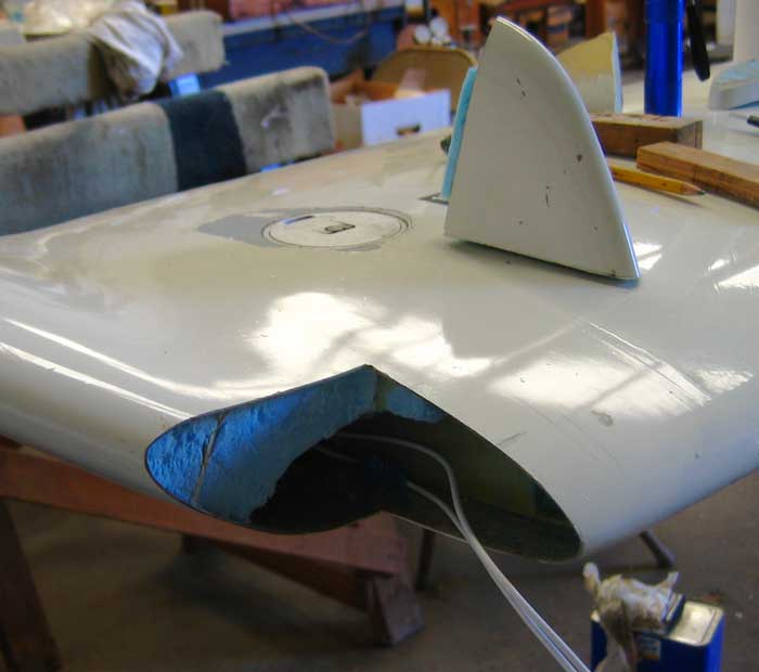
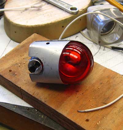
I will build up the front of the core again, this time with fuel-resistant foam, lay up a shear web over it to restore the stiffness lost by cutting the hole, and then mount the light assembly on a floating rib running fore-and-aft. The light, here still in the pliers and tin snips stage, is basically just the standard Grimes unit with the back end of the teardrop cut off and the halogen bulb socket turned crosswise and crowded up against the nav light lens to make the whole thing as short as possible.
[July 14, 2009]
The position lights won out, since I'm still not sure which direction the pre-swirl for the turbo inlet should go. I'm heavily modifying a set of Grimes wingtip lights that I happen to have -- heaven knows why or where I got them -- and putting them under clear lenses where the wing transitions from a straight taper to the upturned dihedral-enhancing tips. There's just barely sufficient room. I'm not sure yet how I will form the lenses, but I will find out in due course, no doubt after ruining and discarding a great deal of Plexiglass. There will also be small white halogen bulbs that will blink -- a sort of poor man's strobe. I don't as a rule fly at night, but for such a complex airplane to be without lights seems incongruous.
This being Bastille day, the music station that I usually have on at the hangar played a rousing Marseillaise, all four or five stanzas -- I lost count. (We forget that the Star Spangled Banner -- a splendid anthem, in my opinion -- also has a whole bunch of extra stanzas.) The refrain of the Marseillaise includes the words "Qu'un sang impur abreuve nos sillons!" -- a remarkably sanguinary sentiment that, roughly translated, means "Let the foreigners' blood irrigate our furrows!" Actually, it doesn't say "foreigner" -- the exact words are "impure blood" -- but one gets the idea. I'm not sure which brand of blood was meant when the words were written in 1792; Prussian, perhaps, or Austrian.
[July 10, 2009]
After fixing a few small things, including a loose connection on the #1 CHT probe and a broken wire on the induction air temperature probe (which has not worked for years -- not that it mattered, since I never use enough boost to worry about excessively hot intake air anyway) I started making a mold for a new turbo inlet box. The turbo air inlet faces aft and is only a few inches away from the firewall; air coming into it has to make a sudden 90-degree turn. Currently, I'm using a "banjo box" to accomplish this -- although it would better be termed a "lute box." This is an expanding chamber with the turbo inlet bellmouth on one side. The idea is that air slows down and spreads out on entering the banjo box, and then gets sucked into the bellmouth. At some point I started to think that on the analogy of a tub drain, the right-angle turn might be made more efficiently if it relied on a spiralling path, like that of the turbo scroll itself. There is some question in my mind about whether introducing some pre-swirl into the inlet flow will mess up the impeller aerodynamics; but the turbo is usually running so far off point anyway that it may make no discernible difference at all. Anway, the idea of the whole project is to improve the breathing of the turbocharger. Actually, I should be working on navigation lights; maybe I'll do both projects simultaneously.
[July 2, 2009]
A benefit of seldom washing the plane is that the dirt on it forms streaks when I fly through moisture, and those streaks tell something about air flow. Today I noticed a faint streak that ran along the left side of the fuselage, starting a couple of feet above the wing. It paralleled the wing surface nicely, then went more or less straight aft for several feet before taking a little jog upward just before the baggage compartment door. The jog puzzled me for a moment, and then I realized that it was caused by by leakage around the door. The leakage is not outward, as you might expect, but inward, because the pressure in the cabin is lower than ambient, being dominated by outward leakage around the windows. This is why cabin vents should not be placed at the back end of the cabin; the pressure there is comparatively high, whereas the pressure in the vicinity of the largest cabin cross-section is low.
[June 29, 2009]
Yesterday we flew back home from Little River. The trip used 23 gallons to go about 420 nm, which works out to 18 nmpg. It's interesting to see how different the block mileage is from the instantaneous mileage. For most of the flight the engine was using about 7.7 gph, at a shade above 50% of power. Our true airspeed was about 159 knots, and so our mileage ought to have been better than 20 nmpg. We had light headwinds, about five knots at the start of the trip and 10 near the end. We did do quite a lot of climbing; we started at 9,500 and eventually ascended to 13,500, where the density altitude was 16,500, for a better ride. I suppose that the time spent climbing at 120 knots groundspeed cut into the mileage, and of course taxiing, runup and takeoff (27 gph!) do too; but I'm still surprised that the difference should be so large. I lean to 25-50 LOP immediately after takeoff and climb at 60% power or so, and 500 fpm. Maybe this is not actually the most economical way to gain altitude. The thing about climbing is that the rate really doesn't matter, because the work required to raise a certain mass to a certain height is a fixed quantity, regardless of how rapidly the job is done. (I was reflecting, as I repeatedly climbed the 85 steps from the beach to the house where we stayed north of Fort Bragg, that our sense that the rate at which work is done affects the total amount of energy expended is due to the way our bodies tire when we work rapidly but don't when we maintain a slower pace.) What affects the cost of climbing to a given altitude is the aerodyamic efficiency of the airframe and the specific fuel consumption of the engine. The aerodynamic efficiency is best around the best rate of climb speed, so that tends to take care of itself so long as you don't cruise-climb (but cruise-climbing may result in a shortened trip time; I haven't looked at that question, which is related to the Carson Speed, since the CAFE races in the 1980s). The specific fuel consumption improves as power output rises, and so it should really be more sensible to climb at a higher power setting, provided that the mixture remains the same.
It might, incidentally, be possible to recover most of the energy expended in climbing by shutting off fuel to the engine and allowing it to windmill with open throttle and coarse pitch during the descent; but passengers could object.
[June 23, 2009]
We got up at 5:00, took off at 6:09, and landed at Little River exactly three hours later, having enjoyed smooth air and a steady tailwind. Everything -- the GPS tracker, the mic key -- worked, except, of course, the flaps. The unreliability of the flaps is troubling; I will probably end up replacing all of the nylon lines with real aircraft stuff, even though it's so damn expensive. What was so odd about this failure was that it occurred when I was extending the flaps before takeoff, and there was no air load on them at all.
In this picture, taken as we crossed the Sierra Nevada into California, if you knew the geometry of the airplane you could infer the time of morning from the shadow of the horizontal tail on the wing. The Steve Fossett crash site is out there somewhere, probably behind the trailing edge.
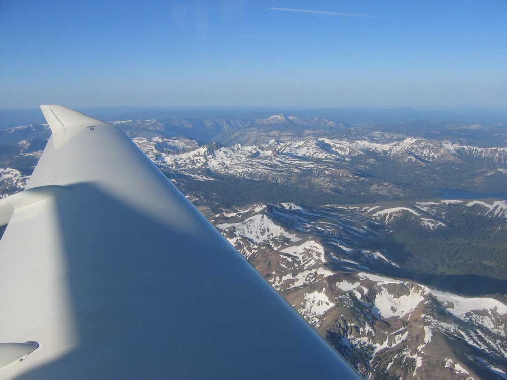
[June 22, 2009]
I am writing this in Cedar City, Utah, where Nancy and I stopped for lunch on the way from Santa Fe to Little River, at Mendocino on the California coast north of San Francisco. We ran into quite a lot of turbulence on the way, and since turbulence is not Nancy's favorite part of flying -- actually, the only part of any flight she likes is parking at the end -- we decided to stay here tonight and leave at the crack of dawn, when the sun has not yet begun to heat up the desert surface. The plane had a couple of glitches at Santa Fe; the press-to-talk switch on the stick stopped working, and a borrowed substitute wouldn't work either. I arranged for a takeoff clearance by cell phone, but when I pulled up to the runway the transmitter resumed working, for no apparent reason. Then, just before takeoff, as I started to extend the flaps, I heard the dreaded pop and saw that the left flap was deploying unevenly. Evidently another one of those infernal NyloSeal fittings had blown off. So no flaps for the rest of this trip. Then the GPS tracker refused to recognize the GPS; it does that from time to time, again for no apparent reason, and pulls itself together on the next flight. And it appears that there is still a very minute fuel seep at the middle flap track on the right wing. I'll probably just live with it; sometimes leaks seal themselves.
June 13, 2009]
Having repaired -- I hope -- the leaks, I put the wing back onto the airplane at the end of the week.
Knowing, now, that one wing weighs 92 pounds, I was able to calculate the actual limit load factors for various fuselage loadings. Each wing, according to my 14-year-old dot-matrix computer printouts, was designed for an ultimate lifting load of 6,450 pounds, distributed spanwise in a manner halfway between a semi-ellipse and the geometric shape of the wing. This results in a moment of 386,000 inch-pounds at the outermost attachment bolt. Adding the weight of the main landing gear (35 pounds each) and the protruding portion of the centersection (which is integral with the fuselage), I arrived at a deduction of 135 pounds. Doubling all of this, so as to reflect the whole airplane rather than just half of it, I subtracted 270 pounds from the measured (well, partly measured, with a small increment for the weight of the flap synchronization system) empty weight of 1,585 pounds, and got 1,315 pounds for the empty weight of the fuselage. (Even knowing the answer, I doubt I could come up with a weight breakdown that would account for it.) Then, I considered three loading conditions: single pilot, two 190-pound persons with 100 pounds of baggage, and four 170-pound persons with 50 pounds of baggage; these add, respectively, 200 pounds, 480 pounds, and 730 pounds to the fuselage weight. Dividing the three totals into the lifting load of 2 x 6,450 or 12,900 pounds, and dividing again by the conventional safety factor of 1.5, I arrived at limit load factors of 5.7, 4.8, and 4.2 G respectively. Weight creep -- or faulty estimation during design -- took its toll; I had intended, originally, that the plane be acrobatic at some loading. It falls slightly short, but no matter -- I am not particularly acrobatic myself.
I am aware that these numbers are slightly optimistic, because the weight of fuel is not uniformly distributed spanwise unless the tanks are full -- that is, unless I have won the lottery and put 142 gallons of fuel into my tanks. Partial fuel weight is concentrated inboard, and so it imposes some additional stress on the wing. The more fuel there is the more it spreads outward, however, and, although I have not yet run the numbers, I feel pretty confident that no fuel load could push the limit load factor, even at the maximum fuselage weight, below the Normal Category value of 3.8 G.
[June 5, 2009]
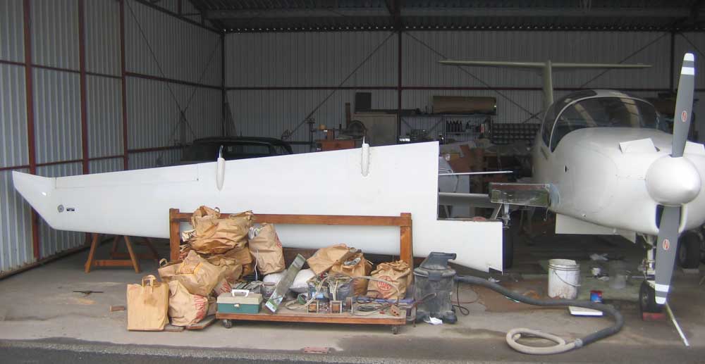
With the help of Russ Hardwick I removed the right wing in order to fix a couple of small fuel leaks. At the same time, I intended to calibate the fuel quantity senders. There are two in each wing, one inboard and one outboard, and in order to calibrate them it is necessary to be able to alternate between full and empty a few times. This is most easily done, obviously, by flipping the wing over. I also wanted to weigh the wing, in order to be able to calculate the actual weight of the fuselage. The senders are now calibrated, and the wing turned out to weigh 92 pounds, which is quite a bit more than the 52 pounds it weighed without tips, ailerons, flap tracks, controls, filler and paint.
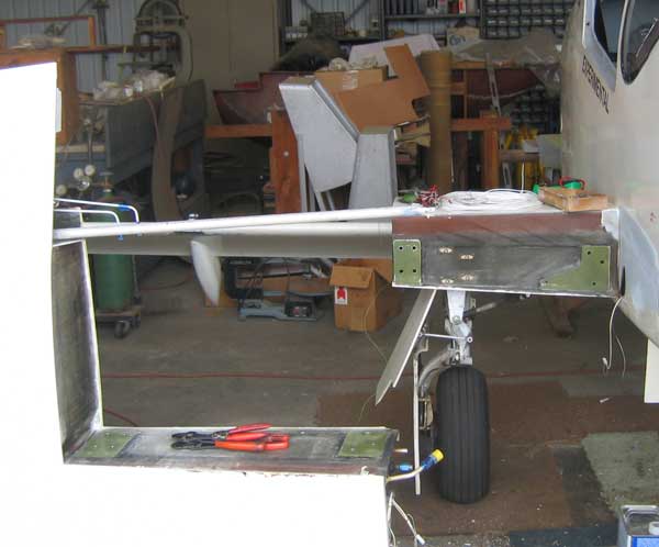
The wing was easy to remove, once I had disconnected all of the electrical, hydraulic and fuel lines and the mechanical controls that connect it to the fuselage. After six and a half years, the faying surfaces showed no sign of fretting or corrosion. The main spar joint consists of two groups of 3/8-inch high-strength bolts, and it seems likely that under normal conditions friction due to clamping action, rather than the shearing strength of the bolts, transmits the load from the wing panels to the centersection. The outboard joint has four bolts and the inboard only three because the lift force is shared between them, whereas the bending moment is upward at the outboard attachment and downward at the inboard. The strips of reddish-brown color along the upper edges of both the wing and the centersection are non-structural; in order to reduce the cabin height, the centersection spar, which is made of carbon fiber and is black, is not as deep as the root profile, but only deep enough to contain the landing gear, which retracts under the seats. The four nutplates on the centersection spar are for the bolts that hold the front landing gear bearing block in place.
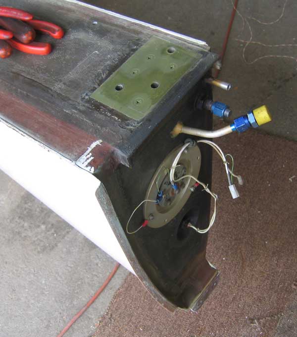
One simple rule that I seem to have been unaware of when I designed this wing is that there ought to be enough space between two structures to allow you to get your hand in. In this case, there isn't; to gain access to the fuel quantity sender, which is in the middle of the large round inspection plate, or to the low-fuel warning float, which is the little black thing in the recess, you have to remove the wing. Very clever. The three lines emerging from the tank are fuel feed, vapor return, and sump drain. I believe that the two shades of green on the aluminum reinforcing plate reflect the areas that were squeezed tightly together (darker green) and those that air could reach (lighter).
[May 31, 2009]
From time to time I have toyed with the idea of reversing the position of the intake manifold runners on my engine. The point would be to eliminate the transverse tubes which now obstruct the flow of cooling air toward the exits. For some mysterious reason this thought has come back to me with more force than usual, and I am thinking that I might actually do it. A little floor-based mocking-up exercise with tracing paper and the factory installation drawing, videlicet
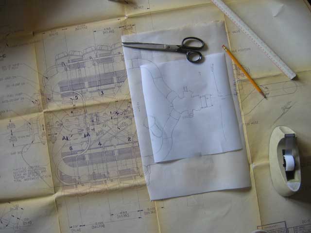
I flew to Paso Robles yesterday with my friend Russ Hardwick. At 12,500 feet, density altitude around 14,000, speed was 174 knots at 8.4 gph.
[May 29, 2009]
Back from our trip east, I did a series of touch and go's today to get more familiar with the takeoff and landing checklist sequences and to get a better feeling for power settings, stick forces and so on during a pattern approach. (I usually fly a straight-in approach to Whiteman.) In the course of six landings, the lowest speed I saw before touching down was 52 knots, as compared with 68 knots without flaps. This suggests a CL of around 2.05 (1.2 clean). It's not clear how close to a full stall that was, and the flaps are stopping a little short of fully deflected because of small amounts of air in the hydraulic lines, so the figure of 2.2 that I mentioned earlier may yet prove to be correct. As always with high-lift devices, however, the exact CLmax is less important than controlling the flare, touchdown point and braking to minimize the required field length. I was able to trim to approach speed (about 73 knots) with takeoff flap (10 degrees), but with full flap (30 degrees), which I used only after turning final, I had to hold some back stick to keep the speed down. The CG was very near the forward limit. Fifteen inches of manifold pressure gives a good 600-700 fpm descent in the pattern with 10 degrees of flap. It appears as if I have a little too much speed on final. If touchdown speed is 52 knots, I should be flying the approach at 67 knots (1.3 Vs). It may be that the angle of attack indicator is not correct when the flaps are extended. But 73 knots is just 1.4 Vs, and it's easy to bleed off the extra speed by cutting the power and starting to flare a little early.
[May 15, 2009]
What was I thinking? Of course it isn't "done." No lights yet, the glideslope is inop, no gear position indicators, wings leaky and incompletely painted, no wastegate. Here is a to-do list which I began in 2002, before the plane first flew. When an item got done, I moved it to the end of the list and changed the font.
M2 to do
left
front
armrest
extend right console down to floor to prevent fouling torque tube
move aileron hinges
make left main gear doors flush
gear sway brace overcenter lock indicator lights
enlarge turbo banjo box
outboard sender, nav, strobe wiring
mechanically attach root fairings
remove
wings:
calibrate all 4 senders
fuel leak in right wing, high, near root
fuel leak at right outboard sender?
fuel leak at middle track
why are low-fuel warning senders weird?
sand, smooth and repaint undersides
toe deflectors above brake pedals
replace nose gear actuator link
replace nose gear retract link
replace nose gear strut?
paint window margins
finish hard static plumbing
cabin/panel lights
nav lights
rotating beacon
alternate static
gas springs for main gear downlocks
canopy seals
window retention screws
adjustable wastegate
smaller alternator
tape pulley brackets
wire colors reversed on pwr/gnd from panel to alt/batt
oxygen system
NG actuating cylinder leak
**********************************************************************
Done
transponder
fuel flow/totalizer
static ports
oil separator
pitot-static-transponder certification
change oil and filter
swing compass
install nose strut gas spring
fit and install middle gear doors
correct position of inboard gear doors; why low?
new tow points
new tires
troubleshoot manual lowering
install and plumb nose gear cylinder
adjust gear control cable tension
reflector plate above cowl floor below turbo
reflector plate on air box
reinforce floor under torque tube support
repair cowl floor under turbo
enlarge cowl inlet
oil cooler radiation shield
overhaul Dukes pump
passenger seat
safety window hinge pins
gas springs for windows
fix short in radio rack
repair and revise turbo mount
put pop rivets in window latch mounting plates
provide cowling water drains
install #2 comm, both navs
replace anti-arcing diode on starter solenoid
move oil separator
fair cowl outlets
NAV antenna
hydraulic reservoir overboard drain
install autopilot
install rear armrests
seat upholstery
engine mount front fairing
reinforce right aileron torque tube support
wing trailing edge skin reinforcement
move air inlets to corners of engine mount
seal around exhaust pipe
carpets
contour wing upper surfaces
service EGT
service artificial horizon
service autopilot
fill and fair wing joints
paint removable parts
paint
reinforce floor under brake pedals
bracket to hold down right baffle shelf
replace leaking brake fluid hose
check voltage regulator wiring per Lipps letter
bracket to hold air duct away from exhaust
prime interior
seal holes in firewall
replace Lord mounts
longitudinal restraint for turbo
straighten lower end of nose gear half-fork
straighten NG retract link
reinforce or replace NG retract link
tiedown rings
electric tank switcher
get artificial horizon
revised turbo inlet air ducting
shift gear lowering backup hex
airbrake
use balsa core for cowl outlets
add camlocs to top cowl
cabin heat
rudder trim tab
#2 comm antenna
floor under rear seats
wingtips
shim front engine bearers
move fuel distributor
display compass card
stall warning horn
provide ventilator valves
repair #2 VOR
12 v outlet
glideslope antenna
marker beacon antenna
improve battery heat shield
replace voltage regulator
repair and reinforce battery connections
battery box insulation and blast tube
flap root fairings
boarding step fairings
move pilot's ventilator to panel
NACA engine air inlet
airbrake warning light
rear seat rails
outboard flap track fairings
airbrake position indicator
install GPS tracker
revise trim system
shimmy damper leak
nosewheel doors
rear seats
make cowl outlet ramps movable
pilot's seat
intercom
GPS rack
exhaust gas deflector plate w/afterbody
outboard flap actuator plumbing
back seat ventilator
roll trim
fill and fair grooves around windows
make new middle flap tracks
flap synchronizer
reinforce middle flap track attachment area
reinforce inner wing skins
A couple of the not yet done items deserve clarification. The nose strut is sufficiently strong, but the diameter of the piston (1.25 inches) is on the small side, and as a result it is difficult to pressurize correctly; either it is too soft and tends to bottom, or it is too stiff and tends to extend fully and stay that way. I have a vague plan of revising one of the old main struts from Melmoth 1 to serve as a nose strut; the piston's diameter is 1.625 in., and it should be less sensitive. I think the turbo would breathe better if the banjo box, through which air entering it makes a sudden 90-degree turn, were larger and differently configured. The wing root fairings are currently held in place mainly by aluminum tape; the idea was to use screws, eventually. As for the wastegate, it is currently the fixed type, with the result that the air throttle butterfly is often partly closed; I think that efficiency would benefit from having the butterfly open and regulating power with the wastegate; but I'm not sure about it, or how big a difference, if any, it would make.
[May 12, 2009]
Leaving tonight for the east. I'll be away two weeks. Someone asked me the other day whether the airplane was "done." In a way it's never done, but I had to admit that, in terms of what I set out to do, it's done. Oops -- no oxygen system yet! Not done yet -- thank God!
[May 6, 2009]
I made a short flight today, and encountered an interesting phenomenon after landing. A good wind was coming down the runway; the ATIS was calling it 10 with gusts to 15, but from the windsock I would have judged it to be more like a steady 15 knots. Anyway, after touching down I wanted to make the first turnoff, but when I applied the brakes the tires just seemed to skid. I had never encountered this behavior before and didn't understand what was happening until I thought about it again a couple of hours later. It was the flaps; even with the airplane in a level atittude they were taking enough weight off the main wheels that I was not getting effective braking. In order to make a short field landing, I would have to retract the flaps as soon as the wheels are on the ground -- equivalent to airliners raising their spoilers after touchdown. Just have to be sure to grab the right handle. (I made the turnoff anyway.)
My passenger pointed out that I still had a hand-lettered sign next to the flap handle saying "FLAPS (INOP)". Before leaving the hangar, I put a little acetone on a paper towel and erased it. The flaps are definitely working.
[May 4, 2009]
I drained the hydraulic fluid from the #2 master cylinder, replaced the Nyloseal fittings with AN flare fittings, pressurized it with air, submerged it in a bucket of water, and found that it did not leak a bit. The suspect joint between the piston and the shaft is evidently tight after all. The leak must have been at one of the two Nyloseal fittings. I re-installed them with more teflon tape, but I'm not confident of that being a permanent fix. Still, the news was basically good; if this cylinder is free of structural leaks, the others probably are too. Sooner or later, one can always get the better of leaky fittings.
Speaking of leaks, after reflection I decided not to take the leaky wing off this week. Nancy and I are going to the east coast next week (not in Melmoth -- too expensive) to introduce ourselves to our granddaughter, who was born on April 21. That would have given me only a few days to work on the wing. Instead, I will wait until after a certain event on May 30 to take the wing off; I will then have a couple of weeks to work on it before needing the use the plane again.
[May 2, 2009]
Nancy and I spent Monday through Thursday of last week visiting friends who have a house in the Sierra about halfway between Fresno and Yosemite. On Friday I removed the leaking master cylinder from the flap synchronizer, but did not have time to do anything with it. It's not actually clear where the leak is -- I thought it was at the main joint where the two pieces of the cylinder join, but I found some fluid inside the piston shaft, which would mean that the threaded joint between the piston and the shaft, which I sealed with Loctite and tested with compressed air, has begun to leak. Having found this apparent leak on the cylinder I had removed, I checked the others and found a drop of fluid at the end of a couple of other piston shafts. The floor below them was dry, so those leaks, if leaks they be, are very slow. They would be comparatively easy to repair, in any case, but I'm not certain that this is the only leak in the cylinder that I removed.
I'm planning to remove the right wing next week to deal with several fuel leaks, including one that kicks in whenever I put in more than about 25 gallons of fuel. I have not had a wing off since spring of 2002; it will be interesting to peer into all the dark places and see how they're doing.
[April 22, 2009]
A milestone of sorts: after six and a half years, Melmoth 2 finally flew with four people aboard. Mike Melvill was in the left seat. Ray Henning and his friend Mary Cunningham rode in the back seats, whose acrobatic entry procedure they accomplished with a good grace. We flew from Tehachapi down to Shafter, north of Bakersfield, where we picked up Ray's T-18 to bring it up to Mike's hangar. It will be stored there until it is sold. Mike has a lot of pictures up on the walls, and he gave us a tour, reminiscing about some of his adventures, which include a 38,000-mile circumglobal flight with Dick Rutan, mostly over water, in two Long-EZs. I thought it was remarkable to reflect that this entire career, this extremely rich life, had been set in motion many years ago by the decision of Mike and his wife Sally (who had eloped and married in their teens) to send away for plans for a weird-looking airplane designed by an unknown character named Burt Rutan.
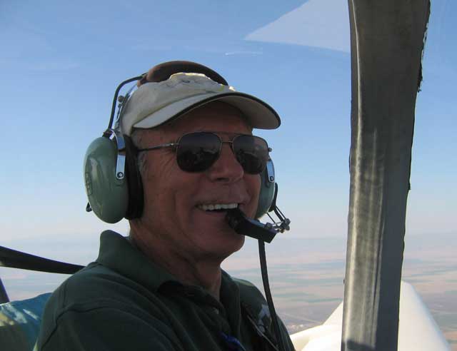
[April 19, 2009]
Yet another video. This one is from the first up-and-away flight, on November 1, 2002. (I had made three short runway hops the day before.) The reasons for the weird temperatures that cut the flight short were two: the oil cooler plumbing was messed up, so that no oil was going through the cooler, and the selector switch that toggled between oil and induction air temperature readings, which share a single instrument, was mislabeled, so that the extremely high oil temperatures appeared as air temperatures, and vice versa. The high oil temperature was the cause of the drop in oil pressure. My comments, after landing, that the engine seemed to lack power are in the category of first-flight observations that are forgotten later. The drag of the landing gear must have made me feel that the airplane didn't have much pep. Anyway, it's never seemed that way since; it has plenty of power. Indeed, except for takeoff I never even use power settings as high as 30/2500 any more.
[April 17, 2009]
I should have added to the discussion below that since the maximum possible lift coefficient of the flapped portion of the wing is much higher that that of the unflapped portion, it would seem that the most likely point for the stall to begin would be just outboard of the flap. It remains to be seen whether this is the case.
In the meantime, now that the flaps, which have occupied me for so long, are working, I have sunk into a sort of pastoral stupor. The only thing I did on the airplane in the past few days was to mount a tiny video camera at the tail; the idea is to tuft the underside of the horizontal and see what the flow looks like during the approach to a stall, particularly with a forward CG.
I did post a couple of new videos on YouTube. Now that I have overcome my natural reluctance to appear ridiculous, I am willing to post just about anything. One of them, which only a parent could love, is of me pushing the plane into the hangar; the other, which is of slightly greater interest (if only because it contains an instance of that piece of film magic called a wipe), shows the extension and retraction of the Fowler flap.
[April 13, 2009]
The main reason for tufting the wing while testing the flaps was to get warning of an incipient outboard stall. It is often said that the outboard portion of a flapped wing is operating at a lower effective angle of attack than the flapped portion, and so the stall will not begin at the tip. Actually, the lift coefficient of the outboard panels is greatly increased by the upwash produced by the flap. Here are plots of spanwise variation of pressure coefficient along the quarter-chord line of the wing, without and with flaps. In both cases the angle of attack is zero. A negative pressure coefficient represents reduced pressure on the wing skin, a positive one increased pressure; lift exists when the pressure on the top of the wing is lower than that on the underside.
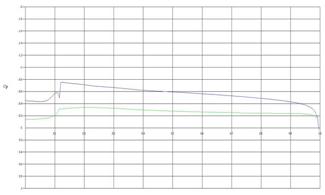
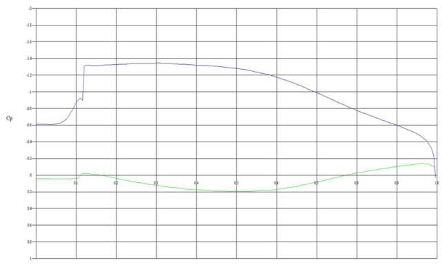
The numbers are hard to read, but the vertical scale goes from +1.0 (bottom) to -2.0 (top) -- it is customary to plot pressure coefficient with negative values going upward -- and the horizontal scale, which represents fractions of semispan, goes from 0 (centerline) to 1.0 (tip). The outboard end of the flap is at about .68 on the horizontal scale. The noteworthy things, I think, are that the lift increment supplied by the flap does not drop off suddenly at the end of the flap, but declines gradually toward the tip; and that a significant portion of the lift increment due to the flap -- the lift can be visualized as the area between the upper and the lower lines -- takes the form of increased pressure on the bottom surface of the wing. When the flap is retracted, the lower surface pressure is uniformly negative; when the flap is down, it is largely positive, becoming somewhat negative only about a third of the way out along the aileron. These differences are due to the flap greatly accelerating flow over the upper surface, while retarding it over the lower surface; our old friend Bernoulli is at it again.
The influence of the flap is felt even across the fuselage; the pressure coefficient at the centerline is -0.6 with flaps down and -0.45 with flaps up.
[April 10, 2009]
The other day, when I was visiting with Burt Rutan, he came out to look over my airplane before I left, and remarked that he had done one of the first layups on it. This was true: He and Mike Melvill came down to Whiteman in August, 1981 and laid up the inner skins of the top and bottom halves of the aft fuselage. This was my introduction to wet layup; I took over from there. The tail cone, from the fin post bulkhead to about the trailing edge of the wing, was made by heating 3/4-inch thick foam sheets in a homemade oven to soften them, and then bending them and gluing them into place in a fixture consisting of particle-board cradles. After the inner skins had been laid up by Burt and Mike, I added frames, then joined the top and bottom. Finally, I sanded the outer surface to give it continuous longitudinal contours. The outer skin was done in my garage during the winter of 1981.
In the picture below, which was taken while I was still a tenant in the big hangar at Whiteman, the frames have been added and the top half has been lifted out of its fixture and set down upright on top of it. The slanted bulkhed in the lower half is the footrest for the back seats. At this point, I felt that I would be finished in another year or so.
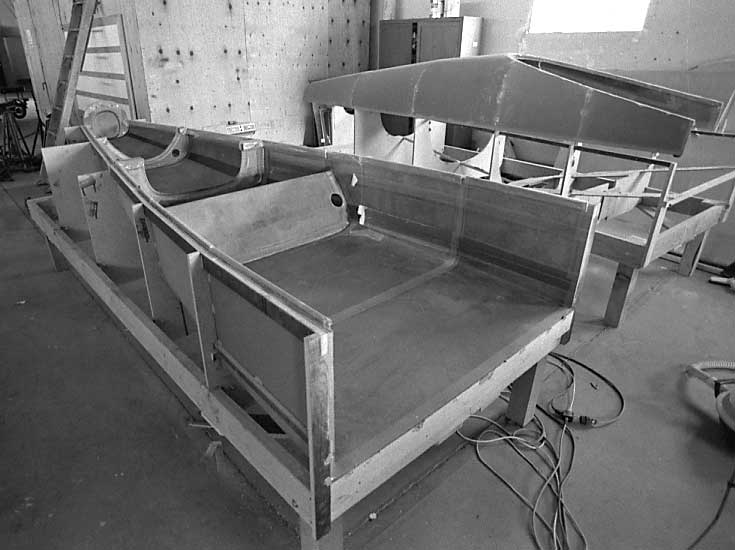
[April 9, 2009]
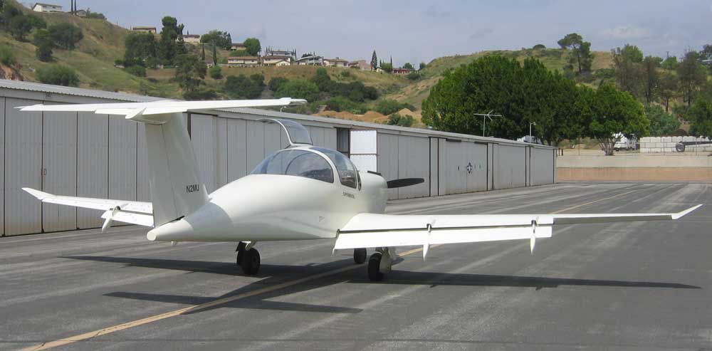
I flew today with full flap. The trim change is not excessive, at least with 50 pounds of ballast in the baggage compartment. I haven't stalled it yet, but it appears that the stalling speed will be around 50 knots at a weight of 1,900 pounds; this corresponds to a CL of 2.2, which is about what I hoped to achieve. (Theoretical section coefficients like 2.8 and 3 reported for big Fowler flaps are two-dimensional values; the complete airplane doesn't do that well because only part of the wing is flapped, the flap has tip losses, there's a download on the tail, and so on.) The flap hydraulics remained pretty dry, with just a couple of remaining drips. Unfortunately there is a new fuel seep in the right wing where I added the track reinforcement gusset, but that shouldn't be too hard to fix.
[April 7, 2009]
I flew out to Mojave on Monday to visit Burt Rutan, whom I first met in 1975, before the first VariEze had been built. I used to see him for lunch very regularly, but I had not talked with him in a long time. He had lost 40 pounds last year and had a close brush with death from constrictive pericarditis, but he now looked sleek and rosy-cheeked. He spoke of the SpaceShipOne project in tones of fond awe and retrospective amazement, and expanded enthusiastically on the absurdities of some of his interactions with government agencies charged with regulating not-yet-existent technologies like thrill rides to space.
Today, I worked on adding a pressure relief valve to the retraction side of the flap hydraulics; I will finish that tomorrow. It appears that one each of the master and actuator cylinders is leaking; the rest aren't, so I feel that I am slowly gaining the upper hand.
[April 1, 2009]
Today I extended the flap to 20 degrees. The hydraulic pressure was close to the relief value setting -- 550 psi -- but the flaps seemed to be traveling freely. I had put a 50-pound ballast into the baggage compartment; this moved the CG to around 20% of chord and alleviated the out-of-trim condition created by the flap. The trim change due to the additional flap deflection was slight. Lots of hydraulic seepage, however, some of it coming from the master cylinders themselves, some from the NyloSeal fittings.
[March 31, 2009]
I realized after taxiing to the runway today that I had not removed the floor panel covering the flap synchronizer, and so could not see the temporary hydraulic pressure gauge. The point of the flight was to find out what pressure is required to extend the flaps fully. I didn't want to taxi back, so I flew anyway, climbed to 7,500 feet, and extended the flaps to 15 degrees. With the CG about as far forward as it ever gets and the airbrake (which produces a nose-up trim change) extended, there was insufficient trim authority to hold approach speed (70 kias); hands off, the nose came down to the "fast diamond" on the angle of attack indicator, that is, something like 1.4 Vs. More flap deflection will tax the trim tabs even more. It's hard to tell, at this point, whether this will be a problem worth doing something about. I could increase the chord of the trim tabs or, alternatively, only extend full flap on short final. One question, which I will be able to answer with a couple of sandbags once I am comfortable with full flap, is whether the trim shortage occurs only with an extremely forward CG. Another question is how much elevator deflection is required to hold up the nose with full flap; I put a gauge on the stick to enable me to read elevator deflection in flight.
[March 29, 2009]
In an attempt to stay abreast of the times, I have uploaded to YouTube a mercifully brief video of Melmoth 2 landing at Santa Paula, shot a few days ago by Paul Lamar, whom I was going to see. The title is "Melmoth 2 landing at SZP". The flaps are at the takeoff setting, and the airbrake is down. My daughter Lily, if she learns of this, will declare it the nadir of vulgar self-promotion.
[March 27, 2009]
I have been concerned about possible flap asymmetry in case of a failure of one of the NyloSeal lines. This afternoon I blocked the flap in place at about 15 degrees deflection and then ran the pump to try to lower it further. Sure enough, one of the fittings popped off. After cleaning up the mess I tightened all of the fittings -- some of them took a full turn or more, which surprises me since I thought I had tightened them pretty firmly when I first assembled them. I don't understand how you're supposed to know when they are properly tightened. When I get the whole system to stay together during, say, a 10-second run at the relief valve setting, which is 550 psi, I'll feel more comfortable about going past the takeoff setting in flight.
The left outboard flap actuator continues to seep fluid from the retraction-line fitting -- a pipe-thread AN fitting, not NyloSeal. I would despair of ever getting some of these fittings to seal if I did not have the example of others to show that it can be done.
Yesterday for the first time I tried a takeoff with the takeoff flap setting; the airplane naturally ascended in a flatter than usual attitude, and felt like an elevator.
[March 23, 2009]
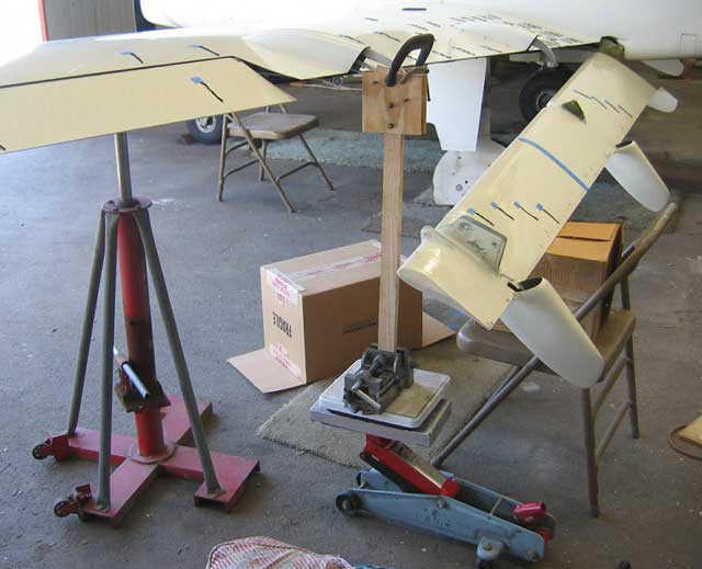
This strange sight is not a structural failure; it is a static load test of the outboard flap track. The idea was to apply a lifting force to the end of the track using the floor jack (the blue thing), with a bathroom scale (the square white thing) between them. The red jack was following the wing without applying any force to it, so that it would not fall very far if the flap track failed. It didn't.
While I was crawling around under the wing I noticed that hydraulic fluid was leaking from the outboard actuator. I removed it and re-installed all the fittings, replacing one that had a deep longitudinal scratch of unknown origin in the conical portion of the male AN flare fitting. The procedure for debugging the hydraulics seems to be to keep dismantling and reassembling things until, for whatever reason, they stop leaking. They can then, I hope, be ignored for many years.
[March 19, 2009]
There's a TFR today that will preclude any flying.
I should clarify something about the flow separation I noted a couple of days ago. I did not make sufficiently explicit that the picture showing reversed flow over a portion of the wing root was taken at 85 kias, which is the flaps-up approach speed. Now, this kind of separation at approach speed has no operational significance. It would matter only if it still existed at the best rate of climb speed, which is around 100 kias at low weights, but at that speed the separation has disappeared. Its presence at the lower speed is of mainly academic interest. I suppose that the fact that the separation vanishes when the flap extends a few inches might have some relevance to the initial climb rate after takeoff, but that influence would be very slight and, again, operationally inconsequential.
I should also explain my use of the terms "approach speed" and "climb speed." Early in flight testing, Mike Melvill identified 68 kias as the power-off stalling speed. The pilot-static system has not been calibrated down to that low a speed, but it is generally accurate and so I assume that 68 kias is about right. It corresponds to a CL for the complete aircraft of about 1.2 at the tested weight. (This is rather on the low side, and might be attributed to the low Reynolds number of the wing at landing speed; the chord, just inboard of the upturned tip, is 20 inches.) Under the conventional definition of approach speed as 1.3 Vs, the corresponding approach speed should be 88 knots. I rely mainly on the Safe Flight angle of attack device to regulate my approaches, however, since it automatically compensates for weight. When I first installed it according to the instructions, which suggest a "typical" chordwise location of the sensing tab, it yielded an approach speed of 85 kias, which seemed close enough to 88 and provided a comfortable flare. The angle of attack instrument has three reference points on its face, corresponding respectively (and roughly) to a slow approach (1.2 Vs), a normal approach, and best rate of climb (1.4 Vs). The angle of attack sensor is on the flapped part of the wing, and so in principle it compensates for flap deflection, since what it is actually sensing is the direction and dynamic pressure of flow in the vicinity of the tab (which looks just like a stall warning tab). The indication is somewhat affected by speed, however, since if the airplane is heavier, say, or the flap is down and the airplane is moving more slowly, the pressure felt by the tab may be different even though the location of stagnation is the same. At any rate, since the AoA indicator is my primary reference for approaches, I am using it to define "approach speed." Thus, when I say that the approach speed is 10 knots lower with the flap in the takeoff position, what I mean is that the AoA indicator is pointing to the "approach" marker (a green band in the middle of the indicator), not that I have measured the stalling speed and then multiplied it by 1.3
[March 18, 2009]
Today I intended to begin extending the flap past the takeoff setting; this would presumably entail larger trim changes and higher hydraulic pressures during extension. When I retracted the flap after takeoff, however, I heard a pop. Sure enough, the same nylon fitting had failed as failed on the 13th. After returning I replaced the nylon line with an armored high-pressure Aeroquip hose, which won't fail. I'm puzzled by the pressure spike that is apparently occurring in the line going to the cylinder that is labeled "Driver" in the diagram under October 13, 2008. I can't see why it would see higher pressures -- and during retraction, besides -- than two other nylon lines that are in parallel with it. Maybe they will be the next to fail.
As expected, if I taxi with the flap extended the middle roller bounces against the track, making a disagreeable rattling sound.
[March 17, 2009]
After repairing the popped hydraulic connection yesterday, today I tested the flaps as far as the takeoff setting. At this point the leading edge of the flap has translated aft almost to the trailing edge of the wing, and the flap chord line is deflected about 10 degrees with respect to that of the wing. The transition from takeoff to landing flap involves little additional aft travel, but the deflection increases to 30 degrees. Here is the scheme at the inboard track, at BL 25, where the total travel is 14 inches:
The takeoff setting reduces the approach speed, as indicated by the Safe Flight lift meter (alias angle of attack indicator), by 10 knots. I don't know what the reduction in minimum speed is, but the flap made a remarkable difference in the landing rollout. Without flaps (that is to say, for the past six and a half years) I have turned off Runway 12 at Whiteman at the third taxiway, with heavy braking; today I turned off at the second (at midfield) , and had to add power to get to it. Although I never minded not having the flaps before, now that I have them it would be difficult to go back to not using them.
At approach speed -- 75 kias with takeoff flap -- the flow attachment is good. Here are tuft shots with the flap about one inch short of the takeoff setting:
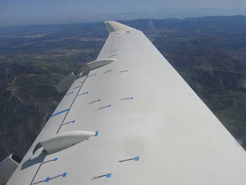
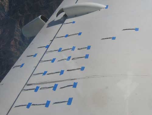
Interestingly (and disappointingly) this is not the case with the flap retracted; there is a pool of separated flow aft of 75% of chord, near the wing root:
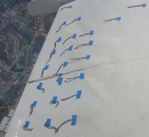
Extending the flap a few inches improves this situation, but probably adds enough parasite drag to cancel the benefit:
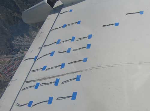
There is still a great deal of testing to do.
[March 13, 2009]
This afternoon I finally operated the flaps in flight for the first time.
As far as it went, the experiment was an aerodynamic success but an hydraulic failure. Having slowed to approach speed (85 kias) at 7,500 feet, I extended the flaps, by small increments, to about half of the actuator travel -- the middle of the flap moved aft about six or seven inches while deflecting less than five degrees. This is much less than the takeoff setting, which involves about 11 inches of aft travel and 10 degrees of deflection. I had tufted the left wing and flap. At the approach angle of attack, I noted some separation in one tuft near the trailing edge of the wing at buttline 48. Even a slight flap extension reattached all upper-surface flow. The tufts on the flap upper surface were straight and steady. At half-extension, approach speed was reduced by seven knots. There was scarcely any trim change. I cycled the gear and the airbrake and did not observe any effect on the flap.
I then retracted the flap and extended it again. In the course of this operation one of the nylon hydraulic line connections popped off, flooding the area under the rear seats with hydraulic fluid and obliging me to return to the airport. The landing, with about four inches of flap extension, seemed unusually smooth and stable, but I may just have been paying more attention than usual.
Although the test ended prematurely, it looked promising -- particularly the lack of trim change, the good flow attachment, and the sizeable reduction in approach speed even with a fraction of the full Fowler travel. Some potential areas of concern are lifting of the long cantilevered slot lip, vibration or flutter of the flap, and flexing of the outboard track, which is an odd shape and difficult to analyze. The only sign of any problem that I observed today was lifting of the slot lip by maybe 1/4 inch. It will probably be necessary to anchor it at a few points.
[March 5, 2009]
Still no electrical power in the hangar, and since the temperature dropped about 10 degrees overnight the epoxy was too cold to pump and the filler on the wing surfaces was not yet sandable. I took off the cowling to inspect the engine, and found that one rocker cover screw had backed out and one exhaust flange nut had fallen off. Fixed those things. One convenience of updraft cooling is that since the bottom of the cowl has to be more or less airtight, stuff that falls off the engine stays in the airplane.
Last night, I figured out the relationship between the outermost shoreline of fuel, as determined by the fingernail tap test, and the amount of fuel in a tank. Here is the result:
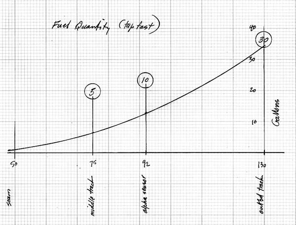
Since the dihedral angle is rather small, the roll attitude has a fairly powerful influence on the results. The circled numbers are conservative, the actual values at buttlines 75, 92 and 130 being 6.5, 12.9 and 34.3 gallons, respectively. Those three buttlines were selected because they correspond to obvious landmarks on the wing; 75 is the middle flap track, 92 the angle of attack/stall warning sensor on the left wing, and 130 the outboard flap track. Now I have to decide whether to rely on memory, carry a copy of the chart in my flight bag, write the numbers on the underside of the wings, or all three.
[March 3, 2009]
I took 29 gallons of fuel from the right tank; with the 26 I took from the left tank a while ago, that makes about 20 gallons more than the totalizer said I had. I last initialized the totaliser 155 hours ago. Assuming an average fuel burn of 8.5 to 9 gallons per logged hour, the totalizer would be off by about 1.5% on the high side. My fuel quantity indicators are not overly reliable at any reading other than zero, so I can't use them to reset the totalizer from time to time. The only thing to do will be simply to add a gallon to the reading after every seven or eight hours of flying. The good side of this is that I am using less fuel than I thought, and so the airplane must have slightly less drag than I thought, since all of my power estimates, which are the basis of drag estimation, are based on fuel flow, and furthermore the plane has been heavier than I thought.
One of the difficulties of my fuel tanks, which consist of the entire interior of the wings, is that it is not possible to check fuel level visually. Since each wing holds 71 gallons, the tanks are never full or even nearly so. I noticed yesterday, however, that there is quite a difference between the sounds produced by tapping with one's fingernails on the underside of the wing where the skin is under fuel and where it is not. Since Loftsman allows calculating fuel quantity for any height of the fuel surface and any pitch or roll angle, it would be a simple matter to create a graph correlating approximate fuel quantity with the spanwise station at which the tapping sound changes.
I was so bold as to make a work schedule over the weekend. According to it I would be able to fly next Tuesday. All went according to plan yesterday, but today the electricity in the hangar was off, and that slowed me down a bit. I may catch up tomorrow, which, if the schedule is to be believed, will be a light day.
[February 26, 2009]
I've filled the holes in the upper surfaces of both wings with foam. It's been chilly in the hangar, and the microballoon paste that holds the foam cures rather slowly, so I haven't yet been able to sand the patches smooth and skin over them. I expect to get the foam filler into the hole in the bottom of the left wing tomorrow. I'll then move the fuel in the right wing into the left wing and add that final gusset. If things go well I should be able to skin all the other patches next week.
[February 18, 2009]
Dodged a couple of bullets. Returning to the hangar on Monday, I found the bolts that I had used to locate the lower-surface gusset too tightly bonded to be removed even with my largest screwdriver. Fortunately, I was able to get them out with a pair of channel-lock pliers, merely wrecking a couple of bolt heads in the process. Then, yesterday, I laminated the second ply of the gusset and two plies of carbon cloth into place, only to find that I could not maintain a vacuum in the vacuum bag, evidently because of the porosity of the fuel tank skin. So I cobbled up a sort of poor man's vacuum bag, consisting of a piece of foam rubber, a piece of plywood, and a wooden crutch pushing up against the plywood from the floor. This morning I found that the lamination had cured very nicely, and looked just as though it had been vacuum-bagged. Here is the completed gusset on the lower surface of the left wing:
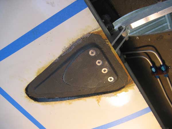
The four bolts are bonded into place with JB Weld, a hard commercial epoxy that fills any voids between the bolt and the gusset. It now remains only to fill up the cavity with foam and skin over it.
Because of the difficulty I experienced in vacuum-bagging the lamination, I am changing the design somewhat. I will attach the second layer of each gusset to the first with the same Click Bond adhesive I used to bond the first to the wing skin, and then lay the two graphite plies over the top of both in lieu of passing one of the plies between them.
[February 13, 2009]
With rain roaring on the hangar roof, I finished digging out the sandwich core on the underside of the left wing and bonded the gusset into place. Sanding while semi-supine under the wing was no fun, but I found that by holding the vacuum cleaner nozzle between my drawn-up knees I was able to intercept most of the falling junk before it fell into my eyes and nose. I used a couple of wood crutches to hold the phenolic gusset in place during cure. Viz:
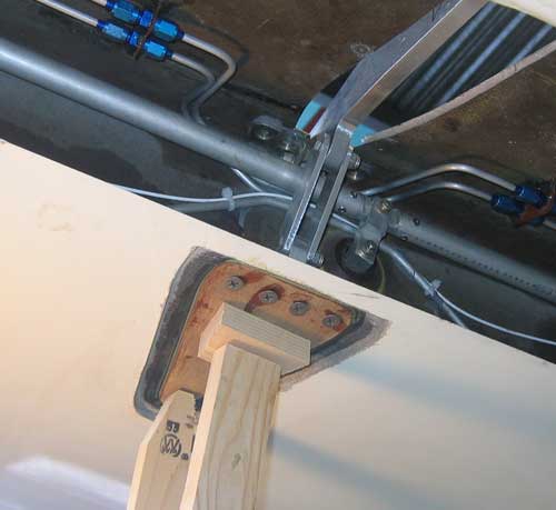
The procedure for this operation, once I overcame my reluctance to destroy the pristine surface of the wing, was first to cut through the outer skin with a very small grinding wheel in a Dremel-like tool, and then to pry the outer fiberglass skin away from the foam core. (This is one of the upper-surface gussets.)
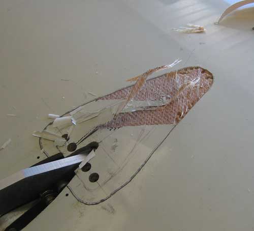
Next, I dug out the foam with a chisel. This brought me down to the layer of epoxy-microballoon paste that forms the interface between the laminate and the core.
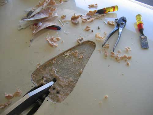
Using coarse sandpaper and a considerable amount of effort, I then sanded away the surprisingly durable microballoon layer. The inner graphite skin, which is the principal wing structure and also the liner of the 71 gallon fuel tank, was now exposed.
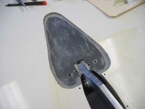
Finally, I bonded the gusset into place.
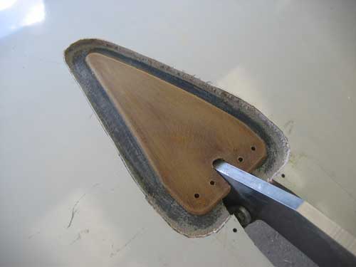
A second, shorter gusset will be added on top of the first one. The final reinforcement will consist of two plies of .100 phenolic with bidirectional carbon cloth between and over them and overlapping the exposed carbon surrounding the gusset. The extra thickness is needed not for compressive strength, but to handle the bearing loads on the four 1/4-inch bolts that join the gussets to the aluminum fittings within the flap cove. (The four holes are now 3/16 in diameter; they will be drilled and reamed when the complete gusset is in place.)
Finally, the outer skin surrounding the hole will be sanded to form a shallow scarf joint, the hole will be filled with foam and microballon paste, and a couple of plies of bidirectional glass cloth will be laid up over the top, dressed, and then, if past experience is any indication, clumsily painted. The whole procedure is repeated four times
[February 12, 2009]
A slight bump in the road. After bonding the upper-surface gusset to the right wing -- the acrylate goop cured much more rapidly today, no doubt because it was warmer than yesterday -- I began prepping the lower surface of the left wing. No sooner had I scraped away some of the foam core than gasoline began to seep out. Evidently the inner skin is somewhat porous, and it is the closed-cell foam core that is providing the final barrier to fuel leakage. There was no discoloration in the foam core, nor any apparent deterioration, so at least the fuel is not devouring the foam or migrating through it. (Auto fuel, with its aromatics, might be a different story.) I learned only after closing my wings that it is customary to coat the inside of integral composite tanks with a layer of pure epoxy. That would have involved a weight penalty of about six pounds, since the wing is entirely wet. In any case, draining 27 gallons of fuel from the wing into a collection of borrowed containers took me the rest of the afternoon. Tomorrow I should be able to bond the gusset on the underside of the left wing. I had intended to do each step of this operation at all four locations before going on to the next step, but evidently I will have to complete the repair to the left wing before draining fuel from the right wing and moving it to the left, which is my only remaining container.
[February 11, 2009]
Removing the wedge of outer skin and foam core from the wing proved to be remarkably difficult. This was gratifying; the sandwich is extremely tough and well-bonded. The outer skin, which consists of two plies of unidirectional material at right angles stitched together, 45/45 to the wing axis, had to be removed with pliers, and came off not as a sheet, as I expected, but in narrow, ragged strips, one layer at a time. The inner skin, the graphite one, is also hard as rock; I expected a little flexing, but detected none. Today I bonded the first gusset into place with the Click Bond stuff, which turned out to be easy to use. It's an acrylate adhesive, like Super Glue, but with a creamy consistency and a comparatively slow cure. You squish two components out of the envelope (I used three envelopes to be safe; I could probaly have gotten away with just two) and mix them up. They start off white, then turn yellowish as the reaction begins. By the time the goop has stiffened up, after 20-30 minutes, it is a dull green color. I was worried that I might end up permanently bonding into place the four clecos that I used to hold down one end of the gusset, so I kept taking them out, one at a time, and wiping them off. They seemed not to stick. Tomorrow I should be able to bond the second upper-surface gusset into place and get one, perhaps both, of the bottom surface holes prepared. I'm beginning to feel quite excited about the prospect of using the flaps.
[February 9, 2009]
The flaps and the middle track fairings are now installed. Apart from some minor seeps, the hydraulic actuation system is working properly. Many of the leaks involve the nylon hydraulic hose fittings, whose pipe threads are slightly smaller than those on AN fittings. After assembling a lot of the components, I found that several winds of teflon thread tape (which I first thought would be unnecessary because the fittings themselves are plastic) seem to prevent seepage, but I have not yet gone back through all the fittings to add the tape. The flaps still aren't ready to be used in flight, however. I have made the phenolic gussets that will be added, in a belt-and-suspenders sort of way, to the wing structure at the middle track attachments. All of my structural epoxy is quite out of date, and on Mike Melvill's advice I ordered a bunch of packets of Click Bond adhesive to attach the gussets. This is an adhesive used for nutplates, surface-mounted studs, and things of that sort, and Mike says it is exceptionally strong. These bonds don't actually have to be especially strong, because the load is spread out over a large area. Super glue would probably do fine. But if the stuff is really bulletproof, so much the better.
Installing the gussets will require removing a triangular patch of the outer skin, sanding down to the carbon inner skin, bonding the gussets to it, and then re-filling the hole and applying a new outer ply with a scarf joint to the existiing skin around its perimeter. The wing skin sandwich consists of a non-structure fiberglass outer ply, a foam (Divinycel) core about a quarter-inch thick, and a structural carbon inner skin. Hence the need to attach the gussets to the inner skin -- it is the one that carries most of the wing loads. This procedure should be quite easy on the upper surfaces, but difficult on the undersides of the wing, where I will have to work lying on my back with sanding grit falling in my face.
[January 28, 2009]
I took the flaps off the airplane in order to do the final laminations, attach the middle track fairings, etc. I won't get them back on until next week. Here is the middle flap track attachment. When the picture was taken the bolts were just slipped temporarily into place, but as of yesterday all of this is permanently assembled.
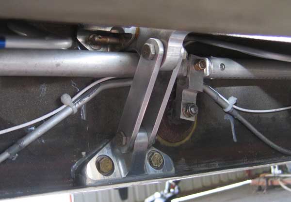
As I originally designed it, the upper and lower attachment fillings were a single piece; but I belatedly realized that in the event of the tension bolts at the bottom tearing out, the aileron pushrod would be jammed and the airplane would become uncontrollable -- which, indeed, it might be anyway if one flap went adrift. This attachment is at BL75.00, that is, 75 inches out from the airplane centerline; the flap extends from BL25.00 to BL140.00. The clevis-like object in the background is an idler supporting the aileron pushrod; there are a couple of these on each pushrod. They reduce the length of unsupported segments of the 3/4-inch diameter pushrod, which otherwise would not be able to take compressive loads without buckling. The 1/4-inch aluminum tube with the wire tied to it is the pitot line; the pitot head is located near the tip of the left wing.
[January 20, 2009]
Discedit frutex, ubi patriam ulterius lacerare non potest.
[January 17, 2009]
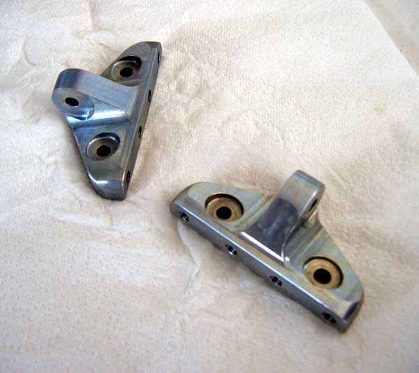
Here are the lower attachment fitting for the center flap tracks, ready to install. Photoshop provided the annual-report-style coloring; they are really just alodined aluminum, not nickel-plated unattainium. They are 3.5 inches wide; all the holes are 1/4-inch. They nest at the bottom of the flap cove, against the rear spar, with two bolts going through the spar into bathtub fittings inside the wing (which is an integral fuel tank), and four bolts threaded into the fittings through gusset plates embedded in the bottom skin. The skin sandwich is a little more than 1/4 inch thick, so the gusset and its bolts will disappear below the surface. The gusset is an elongated triangle, about six inches long, that will be bonded to the carbon-fiber inner skin of the sandwich along an internal rib.
A load of about 2,400 pounds (limit) is applied to the center lug by the fully-extended flap. It resolves itself into a 1,200-pound tensile component, which the gusset carries into the wing skin, and a 1,800-pound vertical component, reacted by a similar downward force from the upper fittings through a 1/4-inch-thick carbon-fiber reinforcing plate embedded in the rear spar. It is customary to apply a fitting factor of 2.0 for critical attachments like these (the standard factor of safety for most primary structure is 1.5), but these fittings are still more massive than is strictly necessary. It was necessary to provide sufficient material around the holes, and I wanted to be sure that the fittings would not distort to any significant degree under load.
I will install these on Monday and cut the shallow notches in the flap leading edges that will be required for clearance when the flaps are retracted.
[January 13, 2009]
Things are finally getting back to normal. I got the upper attachment fittings bolted and bonded into the wings yesterday. I hoped to get the bottom fittings ready to install today, but my mill vise seized up and I had to stop working to fix it. It was interesting to take it apart and see how it's made; there is a lot of inherited ingenuity hidden in these little everyday bits of mechanical engineering. The problem was a crushed ball in a thrust bearing; I removed the fragments and put the thing back together temporarily, while I locate a repacement bearing. I need to drill and tap four 1/4-28 holes in each fitting and make a tool that will enable me to locate the holes from underneath the wing when the fittings are in place. The next step will be to make the four links, two to a side, that go between the tracks and the bottom attachments. Once that is done, the remaining task, before the flaps can be used, is to add top and bottom surface gussets to distribute the center flap track forces into the wing skins. That sounds as if it should take a week, so it may be done by the end of February.
I have noticed, while taxiing with the flaps down, that they vibrate quite a bit, and I am somewhat concerned that they will produce a disconcerting clatter against the middle tracks, which are simply ramps designed to support an upward load only. The rollers may need to have tires. Tires -- that is, bits of hard rubber hose pushed onto an aluminum core -- might have another advantage, namely that of compensating for the misalignment between the rollers and the track surface. The track surface is parallel to the bottom of the wing, but the flap, because it is tapered, describes a sort of distorted cone as it extends, and so the roller as often as not rides on one edge of the track or the other rather than perfectly flush with its surface.
[December 27, 2008]
Having eaten and drunk sufficient over Christmas to make a little famine seem like a good thing, I finally got back to the airport yesterday and spent a couple of hours renewing my acquaintance with the airplane. I drilled the blind bolt holes in the bottom attachment for the left wing's center flap track, and, thanks to my generally virtuous life hitherto, they aligned properly with the ones in the wing.
I've been curious about whether I could begin testing the flaps at partial extension even before I get the surface gussets for the center tracks added. I ran a Cmarc analysis of the flaps in the takeoff position and found that the air load on each one is around 210 pounds, as opposed to about 360 pounds in the landing position. (The moment arm is also a couple of inches shorter.) It was interesting to see that with the flap in the takeoff position, at 1,200 in/sec (68 mph) the lift is 700 pounds greater than it would be at the same geometric angle of attack with flaps retracted; but only 420 pounds of this is applied to the flaps themselves. The rest is owing to increased circulation (that is, more upper-surface suction) caused by the flap, but acting on the wing.
[December 20, 2008]
My prediction (12/8) that I would finishing the various laminating tasks by the 19th was of course incorrect. They always are. The reason was partly that preparation for some of the tasks took longer than expected, and partly that Los Angeles has had a cold snap, at least by our standards, and between the early nightfall (the hangar has no lights to speak of) and the Arctic conditions (daytime temperatures in the low 50s) my working hours have been shortened and the cure cycle of epoxy has been lengthened. Unfortunately, I now won't get back to the airplane until the day after Christmas, because of various holiday activities. I spent most of yesterday's hangar time trying to determine where to drill the holes in the lower track attachment fittings to match, within a few thousandths of an inch, the existing holes in the rear spar. It's a matter of cutting and fitting without being able to see what you're doing, and of course you can't back-drill because the other side of the rear spar is the inside of a fuel tank.
[December 13, 2008]
My week of laminating began with splicing the tops and bottoms of the "canoe" fairings for the middle flap tracks. These are the same fairings as I used on the outboard tracks, and I had made up the half-shells some time ago. To join them, I fastened the top and bottom molds together, slipped the shells inside, and laid up a tape along the seam. This was a little tricky, since the tape is on the inside and I could barely get my hand in. I had to make a special vacuum bag that resembled a sock turned partially inside-out. The inner portion slid inside the shell; coaxing it into place provided a sensation similar, I imagine, to that of artificially inseminating a cow. Both fairings turned out nicely. Here one is before and after the splicing. In the picture on the right the two halves of the mold are lying beside the fairing; if you squint, the upper half looks like a spent Jovian thunderbolt or, as we call them today, a belemnite guard.
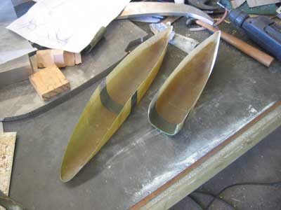
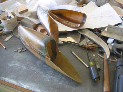
This will be the end result:
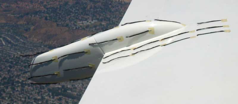
Next week I'll bond these fairings to the flaps, align the nose fairings and provide them with attachment flanges, and notch the leading edges of the flaps to clear the lower attachment fittings.
[December 8, 2008]
Yesterday I flew up to Palo Alto to attend a lecture on electric airplanes by Morton Grosser, a onetime associate of Paul MacCready. Leaving LA I encountered headwinds of 40 knots, and then found the San Joaquin Valley completely socked in with dense fog. I dropped down to 6,500 feet and bent my course westward in order to stay in sight of land while performing thought-experiments about how best to make a dead-stick landing in zero-zero conditions. The headwind slackened progressively as I flew northward, and I got to PAO in 2.1 hours. I was surprised to see at least two TwinStars parked there; maybe the airplane is a fave with Silicon Valley types. I like the airport, but I wish they'd put up a few more signs to help you get back to it. There's nothing on the 101, which goes right past it, to tell you it's there, and even if you know to take the Embarcadero/Oregon Expressway exit there's still no sign on the off ramp to tell you which branch to choose. And even if you manage to stumble on the one well-hidden sign in which the city has seen fit to invest, there are no further signs to help you get your bearings as you get closer to the airport. It's really ridiculous for a place that presumably attracts a certain number of out-of-towners.
I made the return trip in two segments, stopping for a few hours at Paso Robles. I observed 139 kias at 8.4 gph on the first leg, and the same indicated airspeed at 8.9 on the second. Both were at 11,500 feet, but the MP/RPM settings were a little different. Even the 8.4 reading fell short of what should be possible if my F is what I said it is a while ago -- 2.25 sq. ft; that's more like 2.4. There are various possible explanations, including instrument error, mixture setting (since fuel flow is a surrogate for power), and added drag from somethng like a sagging gear door. Since I have so much else to deal with now, I guess I won't find out the answer for a while. The wind had kicked up when I got back to Whiteman, and it was blowing 18 knots at 70 degrees to the runway. The tower instructed me to make left traffic for 30 -- an unusual maneuver -- so that I would be flying my base leg with a headwind rather than a tailwind. A good idea; I'd never thought of it. The approach was bumpy with lots of crab angle, but the landing was smooth -- demonstrating once again that greasers are chance events.
Last Friday I added air to the nosewheel strut, as I do every winter when the temperaures drop. I felt today that the strut was too full, but I noticed that the airplane seemed to track better during takeoff and landing. I don't understand why that would be, but I noticed how much of the nose strut of a Bonanza is exposed, and wondered whether I have been wrong to keep mine with only a couple of inches of piston showing.
[December 3, 2008]
Then along came Thanksgiving, with its interruption, sometime welcome and sometimes not, of the routine of airplane work. During the few hours that I spent at the hangar between then and now, I made another brief dip into the slough of stupidity, inadvertently installing (temporarily) the upper flap attachment brackets and then, observing the misalignment of several degrees in the resulting track position, shaved some material off the bottom of the corresponding lower bracket to match the error in the upper ones. It seemed incredible to me at the time that my extremely careful measurements had yielded such a grossly faulty result, but there it was. Or rather, as I finally discovered, there it wasn't, because once I had installed the correct fittings it turned out that the angles were nearly perfect, and now I had to re-machine the lower bracket to correct my first correction. Fortunately, small amounts of material were involved, and the part, which is still only roughly shaped, remains perfectly usable.
Before I begin actually installing the tracks, I have to do several laminations involving the fairings or "canoes" that will cover the tracks. Trying to be realistic about time for once, I wrote up a schedule, and found that these small operations, which don't sound like much work at all, will probably take seven days. I'm currently staying with friends in the mountains near Fresno, and am going up to Palo Alto next Monday and to Paso Robles on Tuesday; so I probably won't get the laminations done until around the 19th. Just in time for the next Holiday Hiatus. But I suppose there is still a fair chance that I will get the brackets and tracks (but not the surface gussets, which were really the point of this whole exercise) installed by the first of the year. I could then begin flight testing the flaps through the first half or so of their travel.
[November 25, 2008]
This seems to be the stupid season. It finally dawned on me a couple of days ago that the design of the bottom flap attachment fitting would be much simplified if I cut a notch into the leading edge of the flap rather than distort the fitting so as to preserve the flap profile. For a long time I have been thinking about this fitting and how best to make it, without its ever dawning on me that since this portion of the flap is inside a fairing anyway, it's not going to produce any lift to speak of and so the shape of its leading edge is of no consequence. I have now made all of the upper fittings, am nearly done with the first of the two lower ones, and have partially made one flap track. On the other hand, I haven't flown in a month. There must be something wrong with my priorities.
[November 16, 2008]
After cutting away some chunks of glass and foam, I was able to get at the fittings that I had stupidly buried, and to sponge up quite a lot of hydraulic fluid that had pooled in the dead space between the rear spar and the bottom skin. It appears -- I'm not absolutely certain yet -- that the leak was in fact in the line that I first suspected, showing that one can sometimes jump to a conclusion with no evidence and still be right. Good news for prosecutors. I was never able to figure out why the line leaked -- it continued to leak even after I tightened all the fittings mercilessly -- and so I made a new piece of line and used a different flare fitting, and the problem seemed to go away. I now have the upper track attachments fitted to both the left and right wings, and will start on the lower attachments next week.
[November 11, 2008]
I've noticed lately that the hydraulic system seemed to be losing fluid. Since I didn't see any big pools of the stuff on the floor -- either the airplane's or the hangar's -- I speculated that some interaction between the flaps, landing gear, and airbrake, all of which are hydraulically operated, was causing fluid to be dumped overboard from the reservoir. Yesterday, however, I found a pretty big pool of fluid on the left front corner of the airplane floor under the back seats. I put folded paper towels under the nearby connections, expecting to find the leak that way. Today there was no fluid on the towels but a new puddle in the corner. I then realized that the fluid was coming from a closed-off dead space between the bottom of the rear wing spar and the inside of the fuselage bottom skin sandwich. Six hydraulic lines related to the flaps pass through this cavity. Unfortunately -- this was very stupid -- there are connections inside the cavity, but the places where the lines enter and leave the cavity are potted with epoxy -- not so completely potted, however, that fluid could not find a way to leak out. Evidently, at least one connection was not tight. At first I jumped to the conclusion that the line nearest the leak was the responsible one, and I dug it out. I then discovered that there was quite a lot of hydraulic fluid inside the cavity, and I left it to drain overnight. As I was driving home I realized that there was no reason to think that the line alongside which the fluid was escaping from the cavity was the leaky one; it could have been any of the six, and the fluid could be flowing from one side of the airplane to the other before leaking out. The reason I had ill-advisedly potted all these connections into place was to isolate the wheel wells from the cabin; now I think I will have to open up a tunnel on each side so that the lines are accessible, and just pack it with Play-Doh or something to keep the wind from blowing in.
In the meantime, I've been fitting the middle flap track attachments to the left wing. This is fairly tricky, since the top fittings go into a very small and cluttered space, and they need to be drilled to match existing holes that I can't get at. So far, I've had pretty good luck. The underside of the track also needs to match the trajectory of the roller. I'm using a dummy track -- just the front end of a track -- to locate the front limit of the roller travel. Here's the dummy track in place in the left wing's flap cove, seen from below and above:
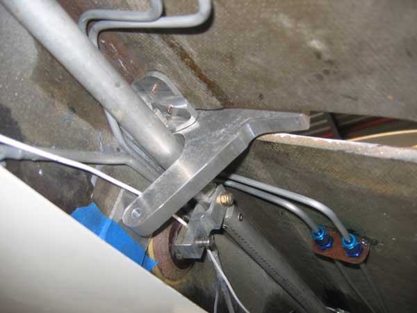
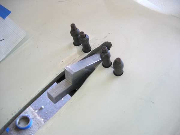
The tube is the aileron pushrod; it is supported by an idler every four feet. The two lines running under the top skin go to the outboard actuator; the lower line is for the pitot tube, which is located at the left wingtip. The clecos will be replaced by 1/4" bolts, and a gusset will spread compressive loads into the inner skin of the sandwich. Only the inner surface of the sandwich is stressed; it is made of carbon, while the outer skin is glass.
Here is the same dummy track lying on a drawing of the complete track. The track is not a slot; it is a ramp, and a single roller on the top of the flap travels along it.
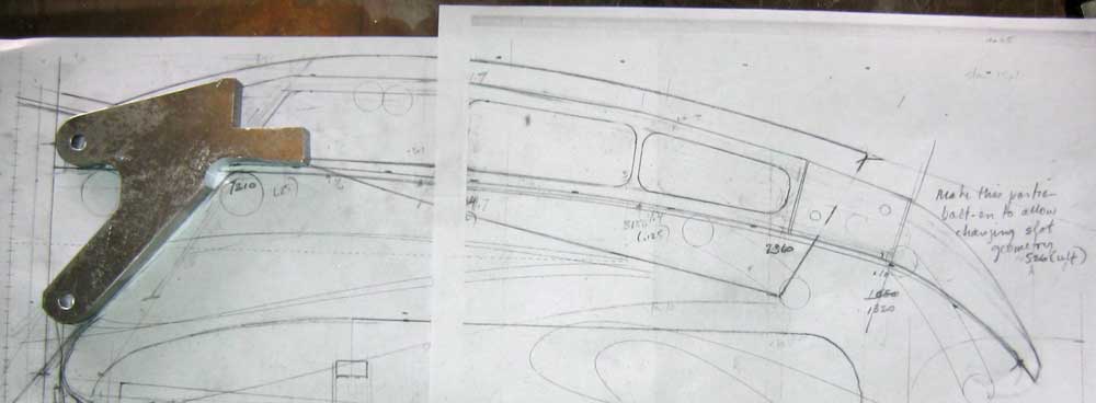
I had a mechanical drawing class in high school, but I seem to have forgotten everything I learned about neatness and clarity. My drawings are all palimpsests -- masses of erasures, pentimenti, multiple views and even different objects occupying the same space on the page.
[November 7, 2008]
In the past couple of weeks I've received innumerable emails concerning the YouTube video that seems to show an exhibition acrobatic airplane losing its right wing in the course of a vertical snap roll, recovering in knife-edge flight, and rolling level just in time to land safely. Non-pilots, who in this case proved more sensible than their license-toting counterparts, generally wrote to ask whether this were really possible. Amazingly, however, a lot of pilots and engineers who should have known better accepted it as the real thing, even though it's pretty obvious -- particularly when the airplane touches down, bounces once, and immediately stops, just like a model -- that it's not. It seems that the tape is actually a clever piece of viral advertising for a clothing line. I'm not sure how you get to the clothing pitch; it must have something to do with an interview with the pilot to which you're supposed to find your way. Anyway, as far as the plausibility is concerned, and apart from the visibly inappropriate dynamics of the landing, I don't believe that any full-size airplane is sufficiently light and powerful to climb vertically on propeller thrust alone, as we see the airplane doing; and a vertical snap roll is a relatively low-stress maneuver that would not be likely to break a competition acrobatic airplane. In fact, it would probably not even bend a Cessna.
I spent the week making aluminum fittings for attaching the middle flap tracks to the wings.
[November 5, 2008]
The oranges are juicier today, the juice sweeter. Ex africa semper aliquid novi.
[November 4, 2008]
I mocked up the left middle flap track, using miscellaneous bits and pieces that I made years ago and then decided to discard. Surprisingly, it all fits together pretty well, although I had to re-route the pitot line around the flap attachment. I machined a sample upper attachment fitting out of maple; today I'll buy some 2024 plate and some new bandsaw blades and start making the real pieces.
First, however, to vote.
[October 22, 2008]
I did a short flight to test the behavior of the trim tab link, whose effect is to double the trim tab area. Nothing surprising. The trim authority at low speed was certainly not doubled, but I think that is because what limits it is not tab area but rather separation, and once the flow on the tab separates it doesn't matter that much whether you have one or two of them. This may turn out to be a problem when the flaps are down, but then again they may increase the downwash angle at the tail sufficiently to limit the amount of trim they require. I didn't test the nose-down trim authority with aft CG, but since that involves high speeds and small tab deflections, there is no separation issue and I'm pretty sure there will be no difficulty.
On the time-honored principle that one should always have two projects going at the same time, I am going to begin work on moving the aileron hinge lines aft to increase their aerodynamic balance and reduce the stick forces in roll, which have always been too high. I have hesitated over this project for a long time because of uncertainty about how best to contour the overhung nose of the aileron. An elliptical, well-streamlined nose makes a larger gap; the gap can be narrowed by making the nose of the aileron more blunt, but that leads to separation at large deflections, reducing the aileron authority. Hoerner reports a 20% increase in section drag due to an aileron slot; applied to 20 square feet of wing area, this represents an equivalent flat plate increment of 0.04 sq. ft. At 60% power, that represents .07 gph, or, at current prices, less than 40 cents an hour, so maybe I shouldn't be concerned. Hoerner does show that the drag increment can be almost entirely eliminated by thinning the airfoil section by 15% just ahead of the aileron. I could do that. There is also the option, seen on may sailplanes, of plastic gap seals that slide on the aileron surface like wipers and flex as the aileron nose rises above the wing surface -- another possibility.
[October 17, 2008]
The flaps now operate so routinely that the process of forgetting the past four weeks of fiddling with them is well underway.
I mentioned on October 10 that I was going to shorten the actuators, but a reader, Ken Phillips (of Cincinnati, I believe), suggested that it might be simpler and less pontincendiary just to add aluminum spacers sliding on the piston shafts to limit the actuator travel. I did so. The left cylinder now reaches its full extension just as the flap reaches its full retraction -- the inboard actuators are installed shaft-forward, so that they extend to retract the flap -- but the right one still wants to go a little too far. I'm going to shorten both piston shafts just a little, by 1/4 inch or less, so that the rod ends that screw into them are not bottomed. That way I'll have some adjustment available in case things move around with use, as they have a mysterious way of doing.
This matter of the travel limits of the inboard actuators involves two variables, the actuator travel and the location of the actuator anchor point on the airframe, relative to the retracted position of the flap. If I had planned things a little better I might not have had any problems, but one of the bad things about composite structures is that you can't drill out rivets or remove bolts and reposition anchor points. Once an anchor is drilled and bonded, there it is. It happens that I unwittingly placed my anchors in such a way that only by restricting the actuator travel to precisely the required amount, with the rod ends screwed all the way into the shafts, could I avoid applying hydraulic pressure to the stopped flap, with undesirable effect (see September 27 below). But then no further adjustment was available. No harm will be done by shortening the shafts a little, however, and that will allow fine-tuning of the retracted flap position.
To celebrate the apparent capitulation of the flap hydraulics, I started working on the linkage joining the two trim tabs, a simple job that I hoped to finish today, but didn't.
[October 13, 2008]
A visitor asked that I post a schematic of the flap hydraulics.
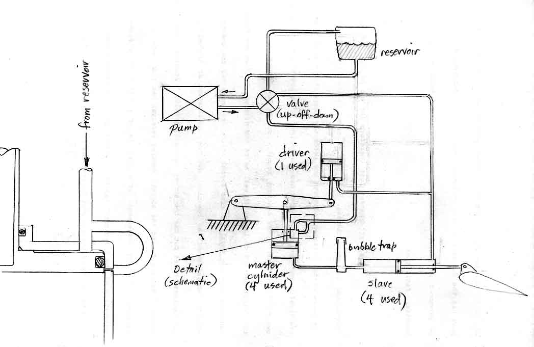
This sketch is simplified; it shows only one master/slave circuit, whereas there are four, and the single walking beam shown is really a bellcrank with five arms, four for the master cylinders and one for the "driver." See January 17, 2008 and January 8, 2005.
The only part that may be a little difficult to grasp is the equalizing function which is indicated in the detail on the left. A very small passage in the wall of the master cylinder allows fluid to pass from the pressure to the vent side when the piston is up against the flaps-retracted stop. As soon as the piston moves slightly (1-2 mm) on the extension cycle, this passage is blocked by the O-ring. The purpose of the passage is to allow the flap to retract fully even if some of the captive fluid has leaked out of the lines between the master cylinders and the flap actuators. The purpose of the single-acting "driver" cylinder is to drive the walking beam and the attached master cylinders to their limits.
[October 10, 2008]
The flaps seem to be working now without any significant leaks, but there is still a problem with the length of the inboard actuators. The best solution I see, since it is not practical to move the points where the actuators are attached to the fuselage, is to reduce the length of both cylinders by about 0.6 inch in order to ensure that they reach their end stops before the flaps do, or at least no later. (This was the cause of the bent shaft I described on September 27. I thought I had fixed the problem, but I was wrong.) I should be able to get that taken care of on Monday. The one synchronizer cylinder that was leaking is now sealed. A small scar from the lathe chuck happened to fall right under an O-ring; it was easily removed with emery paper.
It will be a relief to work, for a change, on some system that does not involve hydraulic fluid.
My statement in the previous entry that all-flying tails automatically compensate for changes in the wing downwash angle was false. I was not thinking clearly when I wrote that. It must be that the immediate, transitory pitching effect of a flap is mainly influenced by the position of the horizontal tail with respect to the wing wake. The long-term effect of putting flaps down, however, is always a more nose-down pitch attitude, if speed is unchanged.
[October 5, 2008]
A longtime correspondent, Dan Fritz, challenged my opinion that deploying flaps would make the airplane pitch down. After reflecting on it, I think he's right: more likely, it will pitch up. What had made me think it would pitch down was my experience with Melmoth 1, and also with my friend Russ Hardwick's Cherokee Arrow, which I flew quite a bit while I was between Melmoths. But both of those airplanes had stabilators, which automatically compensate <<Author's note: This statement is incorrect; see above.>> for the change in effective decalage (the difference in incidence between the wing and the horizontal tail) that the flaps produce. Melmoth 2 has a fixed stabilizer, and it will almost certainly respond to a change in decalage by initially pitching up. Of course, to maintain speed it will ultimately have to settle into a new attitude with the nose lower than before; but it will be necessary to add nose-down trim to get it there.
I spent several hours today wrestling with leaks in both ends of the left outboard flap actuator. It was looking pretty good when I left the hangar, but I'm still not certain that it's fixed.
[October 3, 2008]
I believe that the struggle between me and the flap hydraulics is finally tilting in my favor. The right flap now behaves properly, and the inboard end of the left one keeps pace with it. The outboard end of the left flap is not cooperating, but it has an evident leak, and I have come to suspect that leaks, not trapped air bubbles, were responsible for the initially crazy behavior of the system. I have been gradually eliminating minor leaks all week, and it was after I fixed a pretty significant one -- due to a damaged O-ring -- in the right inboard actuator that the right flap suddenly began working properly. I suspect that fixing the drip in the left outboard actuator will have a similar effect there. Surprisingly, the only cylinder that was completely leak-free from the outset was the one whose shaft got bent and had to be straightened. No doubt there is a moral in that, somewhere.
By luck -- I did not have much leeway in the sizing of the actuating cylinders -- the flap speed appears to be about what you'd want: not exasperatingly slow, but slow enough to allow the pilot to make trim adjustments and to stop the flap if something asymmetrical begins to happen. I am curious to see how the flaps and the airbrake interact -- operationally, that is, not aerodynamically. The airbrake produces a strong pitch up, whereas I believe that the flaps will cause the airplane to pitch down. I imagine that the landing sequence will be to open the airbrake in order to slow the airplane to gear speed (100 knots), then lower the gear, then extend the flap to the takeoff setting, which involves about 10 inches of aft travel and a wing area increase of about 16 square feet, but almost no angular deflection of the flap. Landing flap -- 30 degrees deflection -- would be used only for the final portion of the approach. I hope for a reduction in approach speed (at, say, 2,000 pounds) from 85 to 75 knots. It will be some time before the flaps can be used in flight, however, because I still have to make and install the center flap tracks, which will bear about half of the total flap load.
[September 27, 2008]
This was an exciting week, at least on the scale of what goes on in my hangar. After cycling the synchronizer cylinders alone last week, I installed the actuator cylinders and plumbed them. The inboard ones, which are inside the fuselage and readily accessible, were easy, but the outboard ones are crammed into a small cove in the trailing edge of the wing along with a lot of other stuff like aileron actuators, and I had to learn a particular installation sequence in order to get them in at all. Here's what the little cove looks like with the cylinders and their plumbing in place; for scale, the piston (the slender steel cylinder at right) is 3/8" in diameter.
The pushrod running across the upper half of the picture is 3/4" in diameter and actuates the left aileron. The curvy aluminum thing at right is the outboard flap track. The coiled up wires near the center of the picture are for the outboard fuel quantity indicator, which is not yet in service. The flap actuating cylinder is mounted in a yoke; the cylinder itself is not clearly visible, but it resides in a tunnel in the fuel tank.
With the actuator in place, I more or less charged the lines between the synchronizer cylinders and the actuator with fluid, and tried running the system. The first thing I found out was that I had crossed the lines going to the right outboard actuator, and it was trying to retract the flap while the other three actuators were extending. I fixed that. The flap then operated, albeit haltingly and unevenly, an indication that I had not successfully bled the system. Then disaster struck. After fully retracting the flap, I discovered that the piston shaft of the left inboard actuator was bent like a pretzel. Well, maybe not a pretzel, but at least some non-straight thing. Viz, after removal:

It didn't take long to understand what had happened. Either I once figured this out and then forgot about it, or I never figured it out at all, but the inboard actuators, which are extremely long and slender and are installed backwards, so that they pull the flap down and push it up, have to be adjusted so that they reach their internal stop before the flap reaches its up stop; otherwise the full system pressure is applied to the extremely skinny actuator, and it buckles. At first I wasn't sure I would even be able to get the actuator out of the plane, because they have to be at least partially retracted in order to be removed; but I was able to partially retract the piston despite its elegant hyperbolic arc, and it did come out fairly easily. More surprisingly, I was also able to straighten the piston. My time ran out on Friday before I had a chance to test it again; maybe on Monday I will finally emerge from these woods. Then I can start cleaning up; the airplane and hangar are littered with hydraulic-fluid-soaked paper towels, and look like one of those scenes in ER when the patient is bleeding out.
[September 19, 2008]
Today marked some sort of milestone. I began to bleed the flap hydraulics by running fluid through them from the pump. In order to do this I first re-plumbed the system, bypassing the flap actuator lines, so that the synchronizer module was connected directly to the hydraulic pumpand reservoir. At first nothing happened. Then I became aware that because the lines were more or less empty, the pump was sending fluid from the reservoir to the synchronizers, but returning mostly air to the reservoir. I kept replenishing the reservoir, and gradually got more and more action out of the synchronizers. I also began to discover leaks, however -- that was expected -- and so I didn't completed the bleeding; I'll continue with it on Monday.
Like the gear and airbrake circuits, the flap circuit uses a two-way valve with a closed center. To actuate any of these services, you hold the handle up or down until the action is completed, and then return it to the center. The hydraulic pump runs whenever the handle is not in the center detent. (Actually, there is one exception: the motor does not run when the airbrake handle is moved to the "retract" position; springs retract the brake.) Closed-center valves are necessary because open-center valves would let hydraulic fluid flow freely throughout the system, and no pressure would ever develop. But they are also necessary to hold the flaps and airbrake in any extended position. The landing gear has overcenter up and down locks, but the closed-center valve, which traps fluid in the lines, also provides a backup to the downlocks which proved useful on one occasion (January 28, 2005). I have become aware, however, that hydraulic fluid expands considerably when heated -- 3% increase in volume between 60 and 140 deg F -- and that when the flaps are finally working I should not park in the sun for long periods with the flap fully extended. It is only when the flaps are extended that there is no way for the system to take up the expansion due to heating.
[September 17, 2008]
For the first time, I changed the oil wthout getting the engine hot first. The reason for hot oil changes is, I suppose, to thin the oil and speed its draining. Instead, I removed the plug on Friday and let the engine drain over the weekend. I suppose that one could argue that since running the engine before an oil change gets a lot of the oil up into the passages in the engine, from which it takes a while to drain down, and also spreads it over the engine's internal surfaces, a cold oil change has the advantage of having already allowed some of the oil "up in the engine" to find its way back to the sump. In any case, it was the cleanest oil change I've ever done, because it was so easy to remove the plug without having to avoid all that hot metal. I didn't spill a drop.
After examining the cabin air inlets, I'm puzzled about how water got into the back seat area. I don't see how it could have gotten in through the air inlet, but I can't see any other source for it either. The front is a different story; it's obvious that water could come in there, and would immediately leak down to the floor. I need, at the very least, to make a plug for that inlet. I pulled the rear seat carpets, which had had baggage piled on them for days while they were wet, and laundered them. Most of the mildew smell went away. I was disappointed to find, however, that the Velcro that held the carpet in place had a much greater affinity for itself than for either the floor or the carpet. I need to find a really bulletproof adhesive to stick the Velcro to the floor, and should probably get an upholstery shop to sew the other half of the Velcro to the carpets.
I hope now, with no more travel planned for the forseeable future, to finally get the flaps working.
[September 12, 2008]
We got back yesterday at about noon after spending three days -- parts of four days, actually -- crossing the country. The unexpectedly long return included many hours spent in FBOs' lounges waiting for clouds to lift. I had promised Nancy that we would conduct this entire trip VFR -- several unnerving experiences in Melmoth 1 apparently made her phobic about IFR flying -- and this proved to be a troublesome commitment, although necessary, since without it she would not have consented to make the trip at all. I suppose this no-IFR rule is my belated punishment for the bold go/no go decisions of my youth. She finally did consent to what turned out to be a five-minute climb through clouds to VFR on top when confronted with the threat of being weathered in for four days in Bartlesville, Oklahoma.
I learned on this trip that there are some liberals in Indiana, and that inner America is a culinary disaster area. The plane performed well, with no mechanical problems and cruising speeds in the 160-170 ktas range on an average of 8.4 gph. Despite the engine's habit of oozing oil from many pores, the result of its having been stored for 20 years while I built the plane, it actually consumed comparatively little oil -- a quart every ten hours or so. You don't fly a homebuilt for 37 hours without discovering some problem, however, and I discovered after a few downpours -- while the airplane was parked, not flying -- that rainwater gets into the cabin, apparently through the NACA inlets on the right side and the hinge line at the top of the baggage door. The carpets got soaked at Taunton, and we never had a chance to dry them out before piling tons of luggage on them. They now have a mildewy smell.
[August 27, 2008]
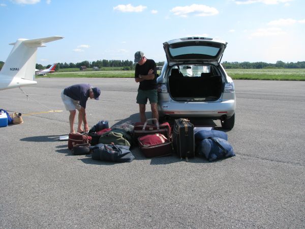
After we collected our daughter from Williamstown, where she had spent the summer as an acting apprentice at the theater festival, we had an unbelievable amount of baggage to contend with. It barely fit in Dave Noland's SUV -- crossover, actually -- and just about filled M2, behind the front seats, to eye level. The thing next to my right foot is a bathroom scale that I brought along from LA, anticipating something like this. Actually, the stuff added up to less than 250 pounds, so the weight was not a problem so much as the bulk. Lily remained in New York, so at least we didn't have to shoehorn her in along with everything else. We landed at Taunton, MA, an airport with the most paranoid and inconvenient security arrangements I've ever seen, and, apart from a sightseeing trip out along Cape Cod, M2 will remain there until we return to California in a couple of weeks.
I used to skydive at Taunton when I was in college, and once came within five seconds of augering in when I somehow failed to locate the D-ring on my ripcord. I landed off the airport in a clearing among trees in somebody's yard, feeling like one of those soldiers who hoped that the Normandy farmyard into which they descended did not belong to a flintlock-toting pétainiste.
[August 17, 2008]
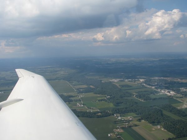
Not surprisingly, we left later on Wednesday than we had planned. We stopped for the night at Gallup instead of somewhere in Kansas, flew to eastern Indiana the next day, and arrived at Orange County (Montgomery, NY) at noon on Friday. Block performance did not match the spot numbers observed during local flights. In theory the plane gets 21 nmpg at 170 knots. In theory, you pick up an average 10 knots or so eastbound from the prevailing wind. But throw in a wind that perversely blew much of the time from the northeast and convective activity that had us at 2,000 agl a lot of the time, and we averaged 145 knots and 17.4 npmg. But the midwest is quite a bit more interesting from 2,000 feet than from 12,000, and the time passed quickly. Used one quart of oil and something like 127 gallons of fuel. The only thing, besides the wind, that didn't work perfectly was my David Clark headset, which began soaking my neck with silicone breast-implant goo somewhere in Nebraska.
[August 11, 2008]
We're leaving Wednesday for the east coast, and so today I was giving the plane a once-over that included draining the sumps. This is something I seldom do, because in almost six years I have never found any water or anything else in them, and the quick-drains have tiny O-rings that drip when little bits of dirt get stuck under them. Sure enough, the left one started to drip after I drained the sump -- nothing in it, as usual. Normally I can get it to stop dripping by letting a rapid stream of fuel flow through it -- I collect the precious stuff in a jar and pour it back into the tank -- but this time that didn't work, and so I had to remove the drain assembly from the airplane to clean the O-ring. This is a difficult and messy job that inevitably includes spilling a pint or so of fuel on the ground by way of my armpits. Eventually I got the drain out, however, and cleaned it. In the duct above it I discovered a little mass of trapped tank scum. On close examination it proved to include quite a variety of mysterious substances and, tragically, the corpses of several ants. Viz:
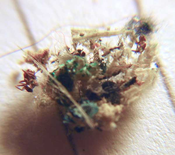
[August 9, 2008]
I was at Santa Rosa, north of San Francisco, yesterday and Thursday, being a judge in a contest run by the CAFE foundation as a part of a multi-year NASA-sponsored effort to improve the technology of general aviation airplanes. NASA is offering substantial cash prizes for the achievement of various goals. The ultimate target is a PAV -- personal aerial vehicle -- that is quiet, efficient, and capable of largely autonomous flight, including automatic navigation and landing. Originally this year's field was to consist of five competitors, but only three ended up participating: a Slovenian-born Pipistrel Virus (34-foot span version), an Urban Air Lambada, and a Flight Design CT, both of the latter built in the Czech Republic. All three are two-seat LSAs with Rotax engines, although the Virus had forfeited its LSA status by installing a variable-pitch propeller. The Lambada is a motorglider with a long, complicated wing; the Virus and CT are polliwog-shaped high-wing designs. The Virus is the more gracile of the two. The Lambada is an old-fashioned airplane, well-behaved in flight and gadget-free. It has the most unmistakeable aerodynamic buffet prior to the stall that I have ever seen; the entire airplane shakes violently, and the engine jumps up and down visibly in its mounts. The Pipistrel is loaded with high-tech equipment, including various electronic displays and an autopilot with altitude hold. It has camber-changing flaps and sailplane-type airbrakes, and a correspondingly varied set of cockpit controls. The CT is most like a conventional small trainer, with the expected controls and round instruments in the expected places. In the picture below, the airplanes (not counting the deceased Douglas in the background) are, left to right, the CT, the Pipistrel, and the Lambada, whose outer wing panels have been removed. The Lambada, which was still involved in some inflight data collection when the photo was taken, is carrying two temporary CAFE pitot-static booms under its wings.
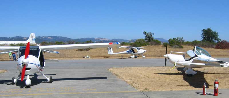
I found the CT to be the least pleasant of the three in flight. I was surprised, in fact, that an airplane with its handling qualities could even come to market. It is directionally unstable; if you floor a rudder pedal the ball goes over the the edge of the inclinometer and just stays there; if you roll without rudder the effect is the same. I thought those flying qualities went out with the Fokker Triplane. It was also much slower, both climbing and cruising, than the Virus, which achieved a top speed of 163 mph in last year's competition; the CT's owner blamed its lethargy on an unhappy choice of a propeller for this contest.
[Note added December 20, 2008. It has come to my attention that I was wrong to say that the CT is directionally unstable. It is stable, since when disturbed by a rudder or aileron pulse it comes to rest flying somewhat sideways, and does not diverge from that position. I should have said that its handling suffers from a lack of directional centering, or, more broadly, that of more than 200 types in my logbooks since 1961, it has some of the most unpleasant handlng qualities I have encountered, combined with entirely lackluster performance. This may not be true of all CTs, however; I gather that there have been some changes from the factory.]
I had a long conversation with Pipistrel's 24-year-old chief designer, who expounded some aerodynamic concepts I had never heard of. It struck me that in different cultures, different ideas are taken for granted, so that, for instance, all sorts of physical disorders are attributed in France to the liver, an organ that goes almost unnoticed in the US, except among drunks.
[August 2, 2008]
I completed the neutral-point hunt yesterday with a flight with 200 pounds of ballast, CG at 40%. The flight was unremarkable and the resulting data set fell nicely into line with previous ones. The stick-fixed NP is evidently at FS130, which is 60% of MAC, just as DWT said. I am setting the aft limit of the CG envelope at FS125, or 45% of MAC. I did discover that there is insufficient trim authority for fast cruise with aft CG. I am currently using only one of two trim tabs, and I expect that hooking up the other one will solve this problem.
[August 1, 2008]
On Tuesday I added another 50 pounds of ballast and did another stick force sweep, which confirmed the neutral point location finding from the first two. I plan to do one more today, with the CG at 40%. This is equivalent to four 170-pound occupants, 40 gallons of fuel and 50 pounds of baggage, and is the design aft limit. It provides a 7-inch static margin, which is pretty ample. In order to go farther aft, I would need to get more sand.
During Tuesday's flight the angle of attack indicator hung in the middle of the gauge. It turned out that the plastic face plate under the needle had cracked and sprung out sufficiently to interfere with the needle. I made a new face plate out of aluminum. It is somewhat crudely painted -- I never have the patience to do things like that well -- but it will serve. A remarkable thing was that when I called Safe Flight, the New York manufacturer of the device, to get some guidance about dismantling it, I talked with Joe Inserro, the same person I talked with when I first got the instrument 35 years ago.
[July 28, 2008]
I was looking through some old documents relating to the design of Melmoth 2 and I was surprised to find that some very early estimates of weight and drag were not too far from the truth. For example, a 1983 weight buildup arrived at an empty weight of 1,375 pounds. The actual weight at the first flight was 1,397. Since then quite a bit has been added, so I don't know how self-congratulatory I should be about the first estimate, but an undated, handwritten document that I think also dates from the 1980s has "Assuming We [ie empty weight] = 1600 lbs," which is not too far from the present value of 1,585. I also did a drag breakdown (handwritten, undated) that came up with an F of 2.5 square feet, which was almost exactly right if you made (as I did) the most pessimistic assumptions about laminar flow on the wings. The current estimate is about 2.3 sq ft.
A dot-matrix printout from an old longitudinal stability program I wrote puts the power-off neutral point at FS 124.11. That seems too far forward; Digital Wind Tunnel puts it at 129.97 or about .60 mac. Today I did a couple of flights to measure static longitudinal stability as a function of CG location. I first flew with a forward CG (113.43; .25 mac is 117.86, and mac is 35.26). I then loaded 100 pounds of sand (in bags) into the baggage compartment, which moved the CG to 118.40. (Actually, I added 10 gallons of fuel as well, but that has a relatively small effect on the CG location.) On both flights, I trimmed for 120 knots, then, without retrimming, accelerated to 160 and then slowed to 90, recording the stick forces required to maintain speeds at intervals of 10 or 20 knots. On the ground, I plotted the results and eyeballed a straight line through each series. Now, in principle I am measuring pounds of stick force per knot, but not having calibrated the Futek I'm just calling it millivolts (mV) per knot. The forward CG line has a slope of .27 mV/knot; the more aft one .19. I just about gasped when I extrapolated to the CG location at which the stick force slope would be zero, that is, the neutral point: 130.2. Given the many approximations involved in the test, that result is for all practical purposes identical to the one computed by Digital Wind Tunnel. It was interesting to see that although the airplane was obviously less stable with the ballast, it didn't feel subjectively worse; it still had good speed stability on final approach and felt normal throughout the speed range. Tomorrow I will add another 50 pounds and repeat the test.
[July 25, 2008]
I intended to make the first flight test with the stick force sensor, which I installed yesterday. But I got involved in plumbing the bubble catcher, and used up all my time on that. Here's the stick force thing:
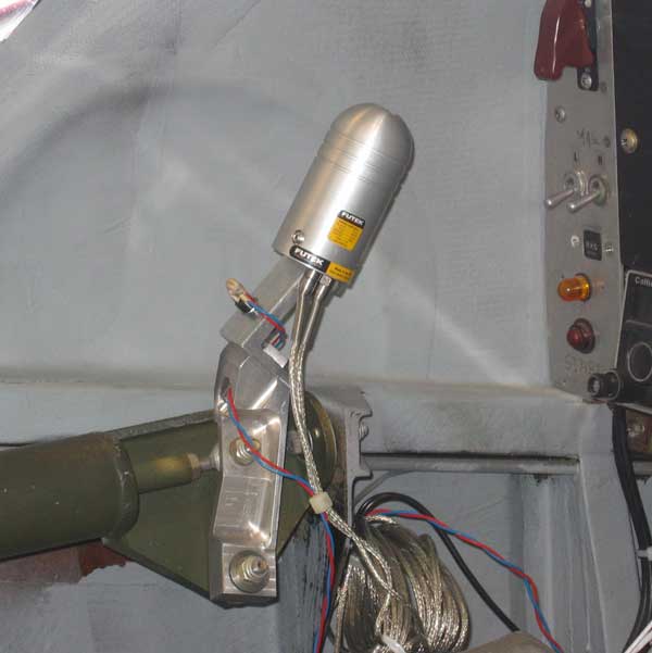
I had to make the L-shaped adaptor between the bullet-shaped sensor, hereinafter "the Futek," and the sidestick mount. The red and blue wires coming out of it are for a press-to-talk switch. The two shielded conductors coming out of the Futek carry both the incoming excitation voltage, which I'm taking from the airplane's 12-volt bus (the airplane electrical system is 28 volt, but the Futek is limited to a maximum of 20 volts), and the output voltages, which are on the order of a few millivolts. One group is for the lateral axis, the other for the longitudinal. I tested it by lifting the weight of the elevator with the stick; it registered around 8 mv, and was quite well damped, so I think it should be possible to get good readings in flight. I have it hooked up to a $15 digital voltmeter that reads in increments of .1 mv, and I'm looking at the X axis, that is, pitch, only. Javier Arango, who will be the ultimate user of all this stuff, is ordering a data logger that will store continuous stick force information in two axes, as well as about ten other channels of data which we have yet to dream up (stick position would be an obvious candidate). Flight path and three-axis rate and acceleration information will be recorded by the Appareo gadget.
Today's progress, such as it was, consisted of beginning to connect the lines between the synchronizer, the bubble catcher, and the hydraulic actuators for the flaps:
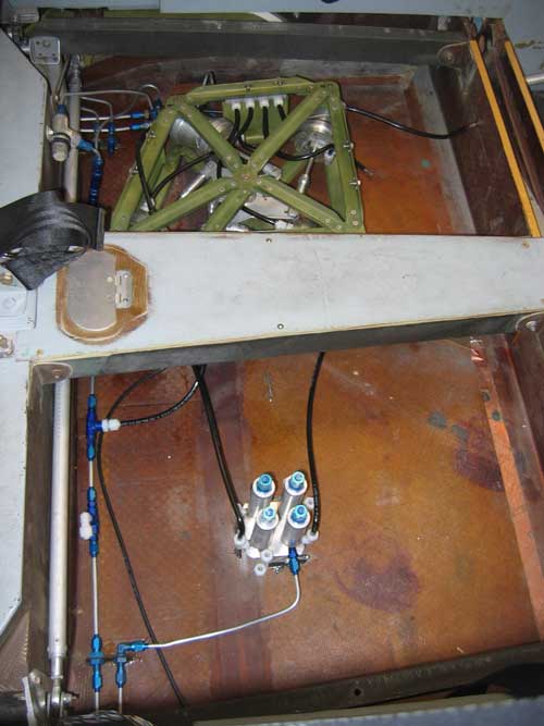
What you're seeing is the compartment beneath the back seats. The front of the airplane is to the left. The floor panels and the seats are supported by four carbon-fiber rails. Each aft-facing rear seat is located by several pins and locked down by a single bolt. The aluminum door in the middle of the floor will eventually have the oxygen outlets under it. The structure along the left side of the picture is the rear spar and main landing gear well; on the right edge are the tracks for the retractable boarding steps. About a third of the synchronizer plumbing is in place.
[July 17, 2008]
We got back from Cape Cod last night at midnight.
I flew a bit today, and thought a bit about what I need to do between now and a month from now when, if all goes according to plan, we will return to Cape Cod, this time in Melmoth 2. One big item is the leak in the right wing tank, which will require removing the wing. That's not a particularly difficult job, or at least it shouldn't be -- it's been on and off many times -- but I don't exactly look forward to doing it. It will pay some dividends, however, such as an opportunity to weigh a wing in its more or less completed form. That in turn will tell me the weight of the fuselage, and allow me to recalculate the actual factor of safety of the wings. It was 10 (ultimate) with two aboard when I designed the plane, but I underestimated the fuselage weight then. The reason for wanting to fix the wing tank leak now, rather than continue to let it go, is that it is located fairly high up in the tank and isn't a problem when there is less than 25 gallons (that is, 50 total) in it. That's fine for local flying, but for a cross-country trip I like to be able to carry 60 or 70 gallons (the total capacity is 142).
Another thing I want to get out of the way is the experimental determination of the neutral point. I described the procedure on June 14. Knowing the neutral point would help to determine the weight limit for rear seat passengers, among other things.
[June 18, 2008]
I finally got the bubble catchers assembled. Temperatures at the airport are forecast to be in the 97-109 range tomorrow and the next day, so I may not get this installed. Still in shock over the Lakers' total capitulation to the Celtics, I am going to Cape Cod to recuperate for three weeks -- plus my son is getting married there on July 12 -- and won't get the flaps moving on their own power until the latter part of July. Here's what the bubble machine looks like. Each tower is an inch in diameter and four inches tall.
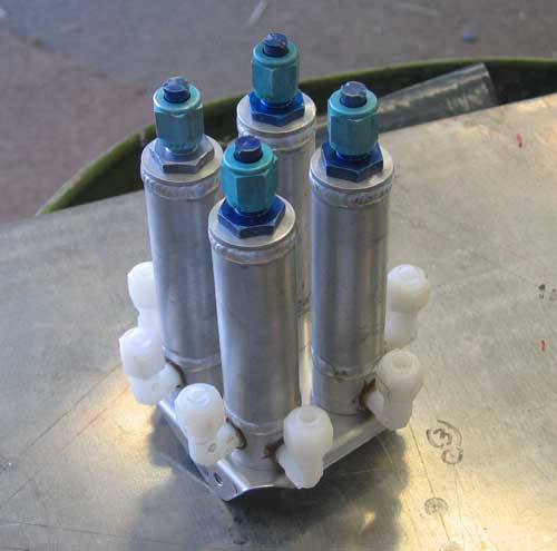
[June 14, 2008]
As part of Javier Arango's project of collecting flight test data on his WWI airplanes, I ran some tests in my airplane with an Appareo GAU1000 flight data recorder which Javier had acquired. This is a little self-contained gadget about the size of a Rubik's cube. It costs $2,000, and performs what would have been considered miracles a decade or two ago, but are now merely routine digital tricks. Using GPS and solid-state gyros and accelerometers, it records location, speed, altitude, acceleration in three axes, pitch and roll rate, and so on. Display software allows you to replay your flight, a la Flight Simulator, but I find that aspect less interesting than the ability to measure a lot of variables like pitch attitude, roll rate, takeoff acceleration, and so on. One puzzling thing, however, is that the reported rates of climb are on the low side, not just in terms of my expectations but also in terms of the altitude changes and times recorded by the instrument itself. I suspect a programming error, but I have e-mailed the manufacturer to try to clear this up. The sevice samples its various parameters ten times a second, then smoothes and stores them at quarter-second intervals. Data can be downloded to Excel for futher manipulation. I expect to have a lot of fun with this (until Javier takes it back).
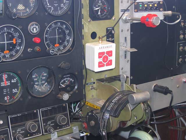
Another gadget Javier got, and which I am going to test first, is a stick force gauge. You can locate the neutral point with this thing by observing the stick force necessary to hold a speed 20 knots, say, below the trimmed speed, and then putting a couple of hundred pounds of sandbags in the baggage compartment and repeating the experiment. With an aft CG the stick force will be less, and a straight-line extrapolation through these two values to a stick force of zero gives you the CG location for zero longitudinal stability. Of course the thing that really matters is pilot comfort, and so the decision about how far forward of that point to put the aft limit of the CG range is a subjective one; but it will be interesting to compare the measured value with the one calculated by Digital Wind Tunnel. Likewise the phugoid period, which can be conveniently measured by the Appareo.
On Friday I picked up the bubble catchers from Flyte-Weld, and will start installing them on Monday, by which time I expect to have recovered from the depression and paralysis brought on by the collapse of the Lakers on Thursday.
[June 4, 2008]
Nancy and I went away for a week to stay with friends near Fort Bragg, on the Northern California coast. Their house overlooks the ocean and a rare (for the area) sandy beach, and we spent hours each day playing "beach boccie," which is a ballistic form of boccie ranging over both dry sand and smooth, wet -- but deceivingly undulant -- tidal flats. It was a lovely time, marred only by our having to drive ten hours each way because Los Angeles chose the day of our departure to undergo a freakish weather phenomenon preclusive of flight (at least for Nancy and me). It was interesting however, that the seats of my 12-year-old Geo Prizm were fidget-free for both long drives. I'm using those seats as models for my pilot's seat, but probably in vain because what matters is no doubt the depth and elasticity in a seat, not just its superficial shape, and those I cannot duplicate.
Today I finished making the parts for the bubble-catchers and took them down to Flyte-Weld, the welder near Burbank Airport whose work I was so pleased with a couple of years ago when I started this seemingly endless flap-actuation project. Chris Mogenson, the Hephaestos of this sooty forge, said he'd do the welding himself -- it's really a job shop whose welders do things by the hundreds, not four at a time -- but that it wouldn't be ready til late next week. I guess I need to find something else to occupy me in the meantime.
I've been having a hard time with the nylon tubing and fittings that I'm using. The description in the Aircraft Spruce catalog of how to assemble the stuff is pretty sketchy. To complicate matters, the 1/8-inch NPT threads on the nylon fittings are smaller than AN standard -- that is, they correspond to a portion of the tapered tap closer to its tip -- and they are really too small for a snug fit in holes that were tapped for AN pipe threads. Conversely, if you size a hole for the nylon fittings, you can't even start an AN fitting in it. I don't know whether an assembly lubricant should be used on the hose connections, or whether a thread sealing material, like teflon tape, or compound, like Tite-Seal, would be appropriate for the pipe threads. I have found nothing online. Of course, I'll figure it out eventually for myself, like most other things; but it's annoying to be so ignorant about such a commonplace product.
[May 20, 2008]
After trying to fill the synchronizer cylinders and lines without introducing any bubbles, I finally concluded that I need a bleeder in each of the four lines from the master cylinders to the actuators. Filling them is just too difficult and uncertain otherwise. These bleeders are actually air traps: vertical cylinders about 4 inches tall with a pressure-tight cap on the top. They're something like an inverted gascolator. Fluid enters and leaves at the bottom, but remains in the cylinder long enough for bubbles to collect at the top. I had one of these in Melmoth 1 and it worked fine. But this will delay the operation of the flaps for another couple of weeks, because I'm going to be away the week of May 23-30. Actually, even when the flap are operating they won't be working, because until I add the middle tracks they can't be used in flight.
[May 10, 2008]
The electrical connections for the flap are done. They were very simple, but some head-scratching was required to figure out how the flap and airbrake were wired, since I did not have a wiring dirgram for them. (Much of the plane has been built impromptu, without drawings, and although I always tell myself how important it is to document everything, I seldom get around to doing so.) I spent a while trying to puzzle out whether I had the flap valve rotating the right way; there was a 50-50 chance that I had it backward, and that the flap would go up when the handle went down. That would be easy to correct by simply swapping the cables at their connection points, but as far as I can tell from comparing the flap valve to the gear valve, I happened to get it right the first time.
I have worried quite a bit about the difficulty of bleeding the lines between the synchronizer and the flap actuators, but it occurred to me this morning that it is actually easy to purge air from the cylinders themselves, and the only bubbles that would be likely to be present would be in the lines. Since the internal cross-section of the smallest cylinder is some 30 times larger than that of the line, and since air does not compress to zero volume, even a four-inch-long void in a line would produce a shift of less than 1/8 of an inch in the position of the flap.
[May 7, 2008]
I had my first hydraulic flood today. The first of many, I'm sure. I was installing the flap actuating handle, and in the course of setting it up I cycled the flap control valve several times. The hydraulic pump wasn't running, but fluid ran from the reservoir to an open connection under the back seats, where the synchronizer is. By the time I noticed what had happened, the reservoir was practically empty, but the well under the seats wasn't.
The flap handle is now in place and working, except for the electrical connection, which I will do tomorrow. Like the gear and airbrake handles, the flap handle rotates a pulley which drives a two-way, center-closed valve, located under the passenger's seat, by means of a cable loop and a second pulley on the valve stem. The cable, which is about eight feet long, runs through flexible conduits. Those for the gear and airbrake are teflon-lined bicycle-brake cable housings; for the flaps I tried 3/16" nylon tubing, which is lighter and seems to work equally well. On the handle there is a cam that actuates the hydraulic pump by means of a single microswitch. The normal position of the handle is centered; to raise or lower the flaps, gear or brake you move the appropriate handle in the appropriate direction and hold it until the action is completed -- a matter of four or five seconds for the landing gear. You then return the handle to the central, valve-closed position. The hydraulic pump runs whenever the handle is out of center. I used this system because the more conventional one in Melmoth 1, which was also hydraulic but with electric rather than manual control, required a bunch of solenoid valves and microswitches and and quite a lot of plumbing and wiring. This one has no solenoid valves, three microswitches, and little plumbing or wiring.
The pictures below give some idea of how the system looks. The first one, below left, shows the flap handle mechanism not yet installed. The pulley, handle, and microswitch are visible, as are the cable, its nylon housings, and the barrel-and-set screw thing that keeps the cable from slipping on the pulley. The next picture shows the handle in place in the panel; the NACA 4415-shaped grip is removable so that the handle can pass through the slot. When it is in its center, neutral position, the handle rests in a detent. The handle, which slides in and out about 1/4-inch with respect to the pulley, is spring-loaded forward and must be pulled slightly aft to clear the detent before being raised or lowered.
The last picture shows the other end of the cable loop. This is the hydraulic jungle under the right front seat (it is also visible, viewed from below, in the entry for January 31, 2007). The gray thing, lower left, is the hydraulic pump, which came from a T-33. The flap valve is the thing with the large, thin hexagonal nut holding it to a green aluminum mount. The cable and its barrel lock are just visible to the left of the check valve with the stamped assembly date of 1966. I hope I can remain functional for as long.
[April 30, 2008]
Last week I got 15 feet of high pressure nylon tubing from Aircraft Spruce, but it turned out that I needed 16 feet. While waiting for the additional tubing to arrive, I took the partially-built flap handle out of the panel in order to complete it. The first problem was to figure out what I had had in mind when I made it, some time back in the 1980s. It gradually became apparent that there was supposed to be a limit sensor that would shut off the hydraulic pump when the flap was fully retracted. This is a feature that the other hydraulic services on the airplane -- landing gear retraction and air brake -- do not have. You just hold the handle in the up or down position until the cycle is complete -- you can tell by a change in the sound of the hydraulic pump -- and then restore it to its neutral center position. When I originally built this thing I didn't anticipate the self-bleeding feature of the hydraulic synchronizer, which requires that the pump continue to run briefly even after the flaps reach their fully retracted position. So I discarded some ingenious-looking little levers and springs and was able to carve away some portions of the handle structure -- saving, I'm sure, a number of grams -- and added a cam and microswitch to turn the motor on at any time the flap handle is not in the neutral position.
During periods of mental idleness I've been trying to figure out how best to fill all the flap-related lines and cylinders with hydraulic fluid without admitting too many bubbles and also without making a huge mess. It's not going to be easy.
[April 16, 2008]
Having fixed the leaky cylinder -- a pipe-thread problem, as usual, solvable with Tite-Seal -- and hooked up the correct end of one actuating cylinder to a master, I confirmed that the travel ratio was precisely what I had calculated that it should be -- not surprisingly, the value of pi having been known with sufficient precision since at least the time of Archimedes. Next, I had to make internal stops to limit the travel of the master cylinders. I machined these today, and the cylinder travels are now within .003 or less of the intended values. So far, so good. Tomorrow I will epoxy the stops into the cylinders, reassemble them once and for all, and install them in the frame.
I had occasion to look at some old photographs of tuft tests of Melmoth 1's double-slotted flap. The quality of the flow attachment was astonishingly good. Here is a shot, taken some time in the 1970's with a camera mounted on the tail, just as I was about to touch down -- in other words, at close to the maximum lift coefficient.
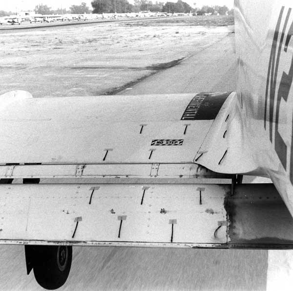
[April 14, 2008]
Today for the first time I connected one of the master cylinders to some of the flap actuation cylinders (the purpose of the master-slave arrangement is to synchronize the four actuating cylinders). Hydraulic fluid is messy at first, like a baby. I found that one actuator cylinder leaked; I sprayed fluid all over the place when a hose connection that I hadn't sufficiently tightened popped off; and I attached the wrong side of the inboard actuator to the master cylinder -- I didn't realize this til I was driving home -- and so the travel measurements I took didn't mean anything. Tomorrow I'll repeat today's experiments, I hope with better results and less splatter.
[March 31, 2008]
I have been derelict. Our son and his fiancee visited from New York, Easter came and went, and there were various household and work duties to discharge -- in short, I have not progressed much. But I have at least installed a good deal of the under-floor plumbing for the flaps. For the first couple of days that I worked on that, I made no progress at all; mostly I just sat in the back of the plane staring at the empty space, shifting the synchronizer and the not-yet-installed oxygen bottle around to see how they would best fit, and trying to decide how to route tubing and locate connections so as to ensure accessibility and minimize the number of expensive fittings needed. It's somewhat like a jigsaw puzzle -- slow at first, but gradually gaining speed as more and more pieces fall into place.
Yesterday I had an e-mail exchange with George Braly of GAMI (the manufacturer of, among other things, injectors whose orifice diameters are tuned to each cylinder in order to ensure even mixture distribution) about the specific fuel consumption of my engine. The question arose because I was asked to repeat some of the windmilling glide tests I did a while ago and wrote about in Flying, and in order to draw conclusions from these tests it is necessary to know two basic parameters that govern the drag of the airplane. One is CDo, the parasite drag coefficient, and the other is e, the span efficiency factor, which is a correction applied to the geometric aspect ratio in calculating induced drag. I obtain e, which is 0.86, from computer analysis using Cmarc; CDo, which is harder to ascertain, comes from comparing measured performance with calculated performance. Performance calculations involve two semi-unknowns, propeller efficiency and specific fuel consumption. My performance calculation program, in Loftsman, uses mathematical models to approximate these parameters, which vary with speed, power, and various other conditions. I had obtained performance charts for my Hartzell propeller which indicated that its efficiency was higher than I thought -- I had assumed a peak of .86, but Hartzell claimed .89 -- and the question now was whether I could pin down sfc with equal precision (and credibility). The program was saying .44 to .45 lb/hp-hr at 55% power, and Braly thought that .44 was a plausible number. But in the course of the discussion he mentioned that the EGT at which best sfc is achieved gets closer to peak as power diminishes. In other words, one should run 75 degrees Fahrenheit LOP (that is, on the lean side of peak EGT) at 70 or 75% of power, but only 25 LOP at 55%. This was interesting to learn, though the actual impact of the information on fuel consumption is probably very slight. Braly also alluded to the well-known general principle that best efficiency is achieved at the lowest rpm and highest manifold pressure consistent with engine limitations; but the applicability of that rule is influenced by the propeller, which may become less efficient, not more, at a given true airspeed, as rpm drops. The loss of prop efficiency with diminishing rpm is very gradual, however, and so it may not really be a significant factor at all.
Unfortunately, the more optimistic view of the efficiency of the propeller, while in no way affecting the performance of the airplane, has obliged me to revise my estimate of its CDo from 0.0214 to 0.0222. How humiliating!
[March 11, 2008]
I finished riveting the flap synchronizer frames today -- my rivet gun couldn't manage the 3/16-inch AD rivets, but my 12-ton hydraulic press upset them nicely -- and was able to mock the thing up to better visualize the plumbing. It looks kind of cool, if you don't realize how stupid it is.
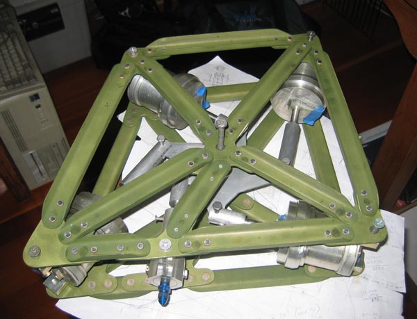
[March 9, 2008]
Although I can't operate my flaps yet, I can analyze them with CFD. Here are a couple of images of streamlines that I found very interesting. The first view, from above, shows the large amount of spanwise flow associated with the deflected flap, and particularly the vorticity generated at the flap root. The second view -- same streamlines -- is just to clarify the relationships in the first. Streamline colors correspond to pressure, and therefore inversely to velocity, with the red end of the spectrum being low pressure/high velocity, green neutral, and blue high pressure/low velocity. The green color of the model is arbitrary.
[March 7, 2008]
In the last three days I've flown twice to Mojave to look in on Ray Henning and his T-18, and once to Apple Valley to touch bases with John Roncz. Roncz had unexpectedly gone to Tehachapi, so I missed him, but the air was very smooth and so I was able to perform the test of cooling drag described on February 16. At 8,500 feet and my customary cruising fuel flow of 8 gph, which is about 55% power, opening the cowl flaps seemed to reduce indicated airspeed from 139 knots to 137. The two-knot difference corresponds to 0.1 sq. ft. of equivalent flat plate area, or about 5% of the total parasite drag.
I chased the T-18 for a while yesterday while Mike Melvill and Ray flew in the T-18. It climbs very well -- 1,500 fpm up to 8,000 feet at Mojave (field elevation 2,538) -- and the airspeed indicator matched mine, which is accurate, perfectly. Ray had earlier mentioned a high cruise of 168 mph indicated at 10,000 feet, which works out to over 200 mph. And he has not yet put the wheel pants on. He has the odd-looking Thorp pants, which cover only the inner half of the wheel; the stock joke about them is that they only slow the airplane down a little. Here's how it looked through my optically imperfect rear window; the dry lake is on Edwards AFB, and the snow-covered peak is 10,000-foot Mt. Baldy in the San Gabriels:
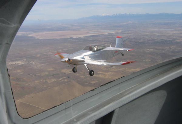
I'm getting close to assembling the flap synchronizer frames. They involve a great many parts that took forever to fit and drill, but I hope to rivet them Monday if I manage to alodine them over the weekend.
[February 24, 2008]
While I grimly revisit the Gestalt of metal airplane construction by drilling holes in what will be the frame supporting the flap synchronizer, others are more interestingly occupied. Last Tuesday Ray Henning trailered his blinding T-18 to Mojave, where Mike Melvill, never one to waste any time, helped put it together and then took it out for a test. The wind was gusting to 29 knots by the time he was on the runway, and besides the tailwheel steering was unacceptably sensitive, so he confined himself to a short lift-off. Yesterday, after replacing the tailwheel springs, Mike made a flight that was cut short after 15 minutes by the non-operation of the alternator and consequent loss of radio communication. Apart from the electrical problem, everything was good, including -- always importantly -- the stall.
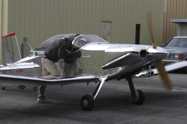
I feel a bit envious, like someone who has college-age kids and whose friend has a new baby. Ray, I suspect, must be greatly relieved and impatient to fly the plane himself. He will have to be careful to avoid any heading that places the sun in a position in which it reflects into the cockpit from a wing. The joke going around Mojave is that the airplane took four years to build and 12 to polish.
[February 16, 2008]
Back home, and flew for a little while. I was looking for smooth air in which to perform a simple test. I was curious whether opening and closing the cowl flaps affects overall drag enough to have a noticeable effect on speed. I've never detected any, but I thought that perhaps a more sensitive test than indicated airspeed would be vertical speed. If I trimmed for level flight with the cowl flaps closed and then opened them, the plane would begin to descend if the drag increased. After repeating this test a few times, I ought to begin to get a consistent impression. Unfortunately, today was not the day. It was bumpy at all altitudes.
Costa Rica hands with birdwatching proclivities will marvel to learn that I took this picture within 12 hours of arriving in the country:

[February 6, 2008]
I'm going to Costa Rica fora weeka. M2 is staying here. No exciting updates til I return.
[January 29, 2008]
During a break in the rain late last week I flew seven touch-and-gos. I've never flown touch-and-gos in Melmoth 2 before, and they turned out to be instructive. I realized that because I usually approach the airport on a long straight-in from the northwest, I had grown accustomed to flying the VASI glide path from a couple of miles out. That was a mistake; it's way too shallow for my airplane or, I suspect, any light airplane. Besides, Whiteman has a telephone pole sticking up right at the end of runway 12, and even though I probably clear it by 30 feet I always feel as though it's about to gouge a hole in the underside of my wing. If you're on the VASI glideslope and miss the pole by a good margin, you have to drop down rapidly to land on the numbers and make the midfield turnoff -- which I seldom managed to do. Flying a series of circuits I realized that a steeper approach felt more comfortable, made for a more natural flare, and allowed me to touch down on the numbers.
For about a week I've been working up the courage to ask one of the local shops if I could use their shear and brake to make the channel elements for the flap synchronizer. A lot of shops, and individuals, don't like to let visitors use their equipment. Today I finally got up the courage to ask. I hadn't even finished the sentence when the mechanic said, "Sure, come on over, they're right there." I had all the parts made inside of an hour.
[January 22, 2008]
Today I found, in a nondescript metal building on San Fernando Road, just east of the old home of Industrial Metal Supply (where, between 1968 and 1973, I bought most of the metal for Melmoth 1), a sheet of .050 2024-T3, which I need for the synchronizer frame. It's become quite difficult to find aircraft alloys in small quanities -- "remnants", as they're called. Industrial, in a new and grander location a mile away, now carries only 6061-T6 and 5052. 5052 is too weak and soft to be of much use, but 6061-T6 is suitable for some applications and is weldable, unlike the stronger aircraft alloys 2024 and 7075. Burbank Metal Supply resembles the old Industrial in miniature, with stacks of miscellaneous materials, aluminum and stainless steel, some pristine, some scuffed and scratched, leaning against walls and stacked in racks. Irv Kaye, who walks very fast and has a somewhat scholarly air, was friendly and helpful, digging through piles of sheet until he found the one, two by three feet, that I needed. It cost $25 -- about eight times what it would have cost when I was building the first Melmoth.
Now I must find someone equally cooperative who will let me use a shear and brake to cut and bend the parts.
I should explain again what this synchronizer does. The flaps are hydraulically operated and are tapered, so the outboard actuators travel a shorter distance than the inboard ones. The job of the synchronizer is to apportion the flow of hydraulic fluid to the actuating cylinders in such a way as to keep the tips and roots in the proper relation to one another and to make sure the flaps move simultaneously. The four cylinders in the synchronizer do this by moving different amounts, kept in step with one another by the single bellcrank to which they are all attached.
Burt Rutan has repeatedly said that I don't need flaps -- his Catbird, an airplane similar to mine, doesn't have them -- and it's true that I have been flying for five years now without them and without missing them. But when I said a few days ago that this was a case of art for art's sake, I could have been speaking of any number of aspects of my airplane that are not really necessary -- or for that matter of the airplane itself.
[January 17, 2008]
Having assembled the cylinders and begun to mock up the flap synchronizer on a piece of tooling plate, I am beginning to feel that this is a case of art for art's sake, unjustifiable by any rational calculus balancing effort and reward. To say nothing of weight. But now that I am this far down the road, I may as well continue.
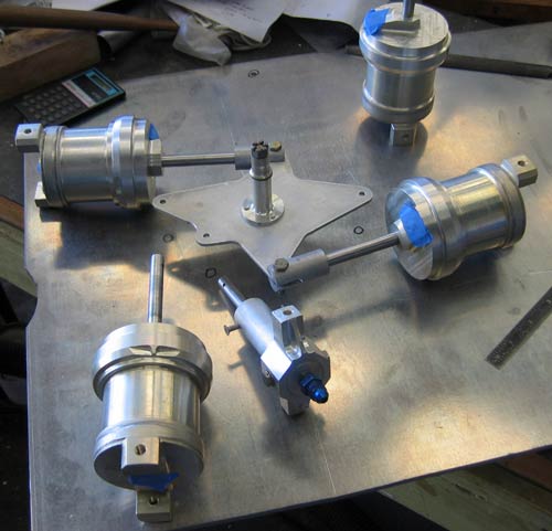
[January 5, 2008]
Yesterday I spent a couple of hours machining a few final pieces for the flap synchronizing system. One of the things I did was take a little material off each of four end caps for the cylinders. These are 3 inches in diameter, and I took away material to a depth of .140 in. over a width of about .6 in. It disappeared into a mess of chips and didn't look like much, but if you calculate the volume removed it turns out to be about a quarter-pound of aluminum. I guess that was worth 20 minutes. As someone in rehab from Christmas, I can testify that machining is faster than dieting. So those parts are at last done, and this afternoon I degreased, acid-etched, and alodined them in the kitchen sink.
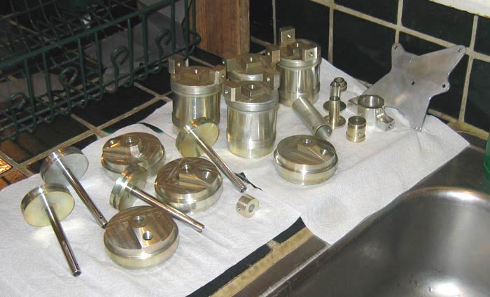
[January 1, 2008]
Well, that's over.
Yesterday was the first time in a week that I've gotten out to the airport and either flown or worked on the plane. I did a little of each.
Nobody has ever asked what the Latin quotations on the home page and on the "Cooling" essay mean. But I'll explain anyway. The one on the home page, "album mutor in alitem..." is from an ode of Horace (Quintus Horatius Flaccus, 65 BC - 8 BC), in which he somewhat grotesquely imagines himself transformed by the fame of his poems into a far-flying bird; literally, it means "I am miraculously changed into a white bird, and light feathers sprout from my fingers and shoulders..." It gets weirder when his legs develop crusty chicken skin; but enough. On the "Cooling" page, the phrase is from the Transformations (usually called "Metamorphoses") of Ovid (Publius Ovidius Naso, 45 BC - 17 AD, a sexy old goat). Telling of the schemes of Dedalus for escaping from imprisonment on Crete, he wrote that the mythical tinkerer "sent out his mind into unknown arts," namely, flight -- sort of like me fumbling around with engine cooling, an art not called "baffling" for nothing.
It never ceases to amaze me that these 2,000-year-old texts come down to us intact.
[December 20, 2007]
Having leaned toward using composites for the supporting framework for the flap master cylinders, I leaned back toward aluminum after reflecting about just how, in detail, I would achieve the desired bearing strength at the cylinder pivots and compressive strength between them. It seemed as though it would be a comparatively complicated layup (two of them, in fact, since the apparatus is sandwiched between two frames, mirror images of one another), with very little weight saving, if any, over an aluminum trusswork of simple bent-up channels riveted to corner gussets of 1/8-inch plate. The corner gussets will be the bearers for the cylinder pivots and the central bellcrank (the "starwheel") to which they are all connected.
It was not until this afternoon, actually, that I ran through all the numbers to ascertain exactly what the stresses are. I am apparently of the "Build first, analyze later" school of design, like the people who did that bridge in Minneapolis. Actually, there were no surprises, since I had a good approximate idea of the forces involved just from mental calculations which I perform, in a fanciful effort to stave off Alzheimers, while falling asleep at night. The main piece of enlightenment that came out of today's more formal calculation was that it is not necessary to regulate the hydraulic pressure in the master cylinders to a lower level than that in the bleeder cylinder; all can run at 500 psi without inflicting excessive loads on the structure. I still need to machine five clevis fittings to join the the hydraulic cylinders to the starwheel, and then I believe it'll be O-ring and hydraulic fluid time.
My hangar neighbor Ray Henning, who has finally finished his T-18 (I think it's been about 30 years in the making), gave me some nylon tubing which will be an excellent, and economical, alternative to the many Aeroquip hoses I had stupidly intended to use.
It will be truly disheartening if this elaborate apparatus does not work as planned.
[December 9, 2007]
Yesterday Captain Tom Huff, the CO of the Naval Test Pilot School at Patuxent River, Maryland, stopped by on his way to the Air Force Test Pilot School graduation at Edwards, and we flew to Camarillo for lunch. I had him fly the plane on the way there, hoping for his assessment of it. Of course if he had thought it stank he probably would have been too polite to say so, but I got the impression that he liked it pretty well. For me, it was a pleasure to watch a skillful and precise professional pilot -- Huff is an F-18 guy, mainly, but he also flies a 210 -- fly my plane, after watching myself fly it for so long. I imagine that playwrights and composers seeing their work performed get a similar pleasure; another person brings something fresh to your perception of the familiar thing. Huff made a nice landing at Camarillo, and I made a rotten one at Whiteman, just to round out the experience.
I've been working steadily on the flap retraction system; the main thing that remains to be made, apart from the center tracks, is the frame that holds the four synchronising cylinders in the proper relation to one another. Originally I was planning to make it of .080 aluminum plate, but at some point it dawned on me that the loads between mounting pivots of the cylinders and that of the starwheel that keeps them in step with one another are compressive, and therefore need something with better column properties than thin plate to keep them in place. I kicked around various options and am currently planning on composite; it seems like the least expensive option, and the simplest to tool.
[November 28, 2007]
On September 17 I wrote about removing the fuel filter and finding in it a great deal of debris consisting, mostly, of bits of carbon fiber and light-colored grit that I think must be epoxy particles released by sanding. I discovered today, to my very great surprise, that by simply holding my Canon PowerShot A80 against the eyepiece of my microscope I can take a pretty good photomicrograph. Here are three shots, the first of the (almost) clean side of the filter, the second of the dirty side, and the third of some of the powder that I scraped off the filter surface. The carbon fragments are on average a couple of thousandths of an inch long.
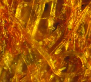


[November 13, 2007]
I flew up to Paso Robles again, this time to talk with a machinist, Richard Galli, who is creating 10 reproduction LeRhone rotaries for Javier Arango. Everything on these engines is machined from huge hunks of solid steel billet -- no castings -- and Galli seems to me a genius with a mill and a lathe. I have no idea how he manages to make some of these parts -- which were originally made, however, in 1915, with machines much inferior to his but, he says, with no less precision in the final results.
The flights up and back -- about an hour each way -- were very smooth, with visibility unlimited and cloudless skies and an OAT of 9 degrees C at 12,000 feet. The autopilot and GPS tracker are working again; now I need to learn the millions of features of my old but highly serviceable Lowrance. So far, like, I suspect, many pilots, I have pretty much confined myself to the "GOTO" command. The other day I could have used the "runway extension" feature, which draws a line several miles out from the runway centerline. It was so murky in Los Angeles that I couldn't see Whiteman's VASI lights until I was inside two miles.
The plane seems to me to have slowed down a bit; I need to put it up on jacks and see whether the landing gear doors have gone out of adjustment. Then again, maybe the overall coating of dust and ash is disturbing the laminar flow.
[November 6, 2007]
I changed my oil today. It took three hours. Every time I do it I promise myself that I will come up with some kind of quick-drain to replace the stock drain plug; but I never get around to it. The problem is that there is very little room between the drain plug and the nose strut in its extended, and even less in its retracted, position. Getting at the plug to remove it is difficult, and made more so by the fact that the engine and the oil are hot. There are various kinds of quick-drains on the market, but even the "low profile" one in the Spruce catalog looks to me as if it takes up too much space. I need a drain that protrudes no more than 1/4 inch below the boss on the sump. I have an idea of how to make one, but as the misery of the oil change recedes in memory I will probably lose the impulse to do it, just as I have on every previous occasion.
[October 31, 2007]
Just got back from almost three weeks on the east coast, where, among more ordinary activities, I logged .7 in a Black Hawk at Pax River. Having been relieved of most of its military equipment, it climbed 3,000 fpm straight up.
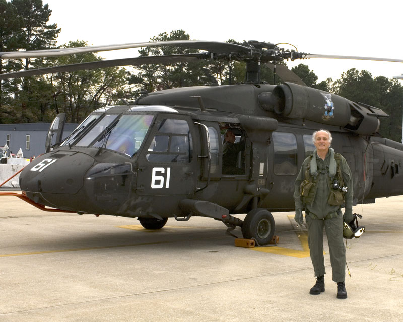
By the way, the Peter Garrison who flew a Seneca into a building in Vancouver on October 19 was not I. I am not sure which of us was the real Peter Garrison, but in any case I am now the remaining Peter Garrison.
[October 5, 2007]
On Tuesday Russ Hardwick and I flew up to Paso Robles for lunch at Michael's, an airport restaurant of the better sort or, better, a restaurant of the better sort that happens to be located at an airport. We parked in front of the restaurant, alongside a handsome Lancair 360. After lunch we got into a conversation with the owner of the Lancair, who had bought it from someone who had had it built by a professional builder. "There are the people who like to build," the pilot declared, "and then there are the people who like to fly." Obviously, he preferred to fly and assumed that I preferred to build.
On the return, while descending into Whiteman, I throttled the engine back to idle and compared rates of descent with fine and coarse pitch. (The subject was on my mind because I had written in a couple of recent Aftermath columns that glide can be extended by putting the prop in coarse pitch.) Fine pitch, which causes the engine to turn at higher rpm and therefore absorbs more energy, yielded 1,200 fpm, against 1,000 fpm for coarse pitch. Now I am curious to know the zero-thrust sink rate; theoretically, it should be around 750 fpm under the same conditions. This figure, which emerges from my computer simulation, implies that the engine is absorbing about 15 horsepower when the propeller is in coarse pitch. I have a 1972 Lycoming report, Peformance Characteristics of the Continental IO-360-D Model Engine, which includes a plot of friction horsepower against rpm; it shows a nearly straight-line variation between 12 hp at 2,000 rpm and 28 hp at 2,800 rpm. (A close fit, if anyone cares, is 5.16x^2 - 4.27x.) I'm not sure whether this includes pumping losses, which could be at least partly eliminated on the test stand by plugging up the intakes and exhausts. I'm also not sure whether it's better to have the throttle open or closed in a power-off glide, or whether it even makes an appreciable difference. A vacuum cleaner runs faster with its intake plugged, but it's not a positive-displacement pump and so the analogy may not be a useful one.
To measure zero-thrust sink rates, I would have to put a microswitch on the engine block behind the propeller flange and detect the point at which the crankshaft, which has measurable end play, shifts from thrust to drag. Knowing the zero-thrust sink rate is one way to measure drag; the rate of sink represents the release of potential energy at a known rate, and can be translated into horsepower at least as reliably as fuel flow can.
Speaking of sink, I tried a lean climb on the trip to Paso. Rather than climb at 1,000 fpm at 28/2500 and 12 gph with a rich mixture, I set up 27/2400 and 8.4 gph at about 50 deg. F lean of peak, which gave 500 fpm. I later ran the math and found that the lean climb saves 0.2 gallons or, at current prices, about 90 cents; on the other hand, it takes about three minutes longer to cover the first 40 miles of the trip. Is my time worth 30 cents a minute? Depends whom you ask.
On Wednesday and Friday I worked at Homer Knapp's machine shop -- he is a motorcycle machinist and pilot whom I first met in the early 1970s in John Thorp's circle -- on the flap synchronization cylinders. They are now honed and the barrels and caps are threaded. There is still some machine work to do on the caps, but the honing and threading operations have loomed before me for years now and I'm glad to have them finally taken care of. Homer did the first three barrels and had me do the fourth, which I only slightly messed up. I did the inside threads on all four caps without ruining any of them -- a minor miracle.
On Thursday I bit the bullet and took my autopilot over to Mid-Continent Instrument at Van Nuys airport for repair; I also removed my quaint eight-day wind-up clock, which would run for barely eight minutes on a full winding. I thought it needed cleaning, and took it to the local watch repair place in Echo Park only to learn that the elderly horlogier had "passed." For the past two days, however, the clock has been ticking away merrily on my drafting table, evidently more at home there than in the airplane. Perhaps, like many people, it prefers lying on its back.
I got a message this afternoon that the autopilot is fixed and the bill is $185. Not bad for an airplane part. I can amortize it with 200 lean climbs.
[September 20, 2007]
I flew around for half an hour just to remind myself of where the buttons and knobs were. I was somewhere north of the San Fernando Valley, climbing through 6,000, scanning the sky like mad because this is the area through which flights inbound to Van Nuys and Burbank pass, when I briefly looked at the instruments and then looked out again to see a King Air passing in front of me a few hundred feet away. It was incredible that I could have failed to notice it moments earlier, since I was being quite conscientious about looking for traffic. It's difficult, after an experience like this, to have a lot of faith in "see and avoid." It also makes it seem particularly strange that Cessna's new light sport airplane, the 162, which is featured on the cover of Flying this month in a picture so murky that the airplane can barely be distinguished from the background, is a perfect clone of the 150, an airplane so notoriously difficult to see out of that its mere existence demonstrated the value of pure chance in avoiding midair collisions. Evidently the designers at Cessna, who should know, feel that visibility plays a relatively minor role in air safety.
[September 18, 2007]
I found the filter element at Kal Nelson's, or rather at K&P International, which has replaced Nelson's, the disappearance of latter enterprise being, as an employee of the new one said to me with a mysterious smirk, "a long story." After installing the new filter element, I cut the old one apart. It consists of 27 square inches of resin-coated paper. Under the microscope it is revealed to be a dense tangle of glossy orange fibers whose diameters are on the order of a few ten-thousandths of an inch. I found that the dirty side was loaded with a lot of debris but far from clogged. None of the long glass or carbon fibers had found their way to the clean side, but a few particles of amorphous whitish stuff resembling salt had, together with some very small fragments of carbon. Some of these, however, may have been transferred to the clean side by my less than professional handling of the sample. The filter seems on the whole to have been very effective. Possibly, however, it would be a hazard in freezing conditions if there were any water in the fuel. If the filter, which has no bypass, managed to become clogged with frost, it could shut down the engine. It would perhaps have been better to put it in the engine compartment, where it could have been kept warmer and would, besides, have been easier to get at.
The pictures below show the compartment that is below the pilot's thighs. The airbrake has been propped open to allow access to the compartment. The black object with the groove down the middle that runs across the top of both picures is the main spar. The filter housing is the bright aluminum thing on the left. Immediately to its right is the fuel shutoff, whose handle is on the other side of the bulkhead; to the right of that is the gascolator -- a genuine antique. Then comes a shaft that is part of the backup manual gear-lowering mechanism, and then, vanishing from the edge of the picture, is the electric boost pump. The next picture takes up where the first leaves off, with the electric boost pump (the red and maroon thing with the yellow label on the bottom); the two aluminum valves are fuel tank selectors, one controlling feed and the other return. They may be operated manually or electrically; the motor is the tan cylinder above the valves. The two springs are return springs for the airbrake, which is the black surface at the bottom of the picture; the cylinder that operates the airbrake is just above the springs. The back end of the hydraulic pump is at the extreme right.
There are some photographs of the other end of this action-packed compartment at January 31, 2007.
[September 17, 2007]
I have been making the fairings for the middle flap tracks at a relaxed pace, one a day. Today, having finished the fourth of six pieces, I thought I would go flying, but then decided first to drain the sumps and gascolator and check the fuel filter. The fuel tank sump drains disgorged, as usual, a few largeish grains of this or that -- you can never tell what the stuff is -- and no water whatever. They have never shown any water, although the tanks are never close to full; I suppose this is my reward for living in a dry climate. Often one or the other of them begins a slow drip after being drained, and it becomes a big production to get rid of whatever bit of smut is sticking to the tiny O-ring. This time that didn't happen, and I proceeded to the gascolator, which is located above the airbrake in the wing centersection. It always drains very slowly, yielding a deep blue liquid -- the dye in the avgas seems to collect here -- and a small amount of finely divided black grit that almost looks like some sort of melanoprotozoa when random turbulence -- or Brownian motion -- stirs it up. The gascolator, too, was kind enough to re-seal without starting to drip.
I then opened up the fuel filter, which, just between us, I have not looked into since 2002. The filter uses a pleated paper element, and there was quite a lot of scum in it; in fact, when I had mined most of the stuff out of the pleats it amounted to perhaps half a cubic centimeter of what appeared, once dry, to be a fine gray powder. Under a microscope, however, it revealed its true identity: a pick-up-sticks-like maze of black and transparent shafts of graphite and glass, mixed with clumps of shapeless light-tan debris which I take to be epoxy dust. Using as a gauge one of Nancy's hairs, which, by the way, was astonishingly clean and regular in shape, resembling an acrylic extrusion, and which I mic'd at .0017 inch, I estimate that the fibers are about two or three ten-thousandths of an inch in diameter. Most are three or four thousandths long, but a few are as long as .010 inch. I'm awfully glad I put in the filter; most airplanes don't have extremely fine fuel filters like this, but the debris the filter caught could have caused no end of trouble in the injectors.
I imagine that the filter element must be pretty well riddled with this gunk, and that I need to replace it rather than attempt to clean it. (It is customary, in any case, to replace paper filters and not to re-use them.) The element is a Purolator part, AN6237-1. I thought I had a couple of spares, but I could not locate them in the hangar. (Actually, it would have been miraculous if I had.) The local parts shop, Vista, didn't have one, but said they could get one by tomorrow. I decided instead to try my luck at Norton Sales, which has incredible amounts of incredible stuff, but, incredibly, didn't have this. I then thought I might find it online; all of the places offering it for sale, however, are electronics parts suppliers, so I'm afraid that if I order one I'll end up with a capacitor or something instead. Nothing at Aircraft Spruce. I'll try Luky's tomorrow -- the somewhat diminished avatar of the once magnificent Joe Factor Sales -- and then Kal Nelson; if those fail I'll be back at Vista, where I hope it doesn't turn out that they can't get them after all.
[September 8, 2007]
I revisited the stress analysis of my flaps more than three years ago (see March 11, 2004), and found that the loads that I assumed when I built them in the first place, some time well back in the twentieth century (why didn't I make my programs print the date on everything?), coincided closely with the new calculations -- showing, for one thing, that the old methods worked as well as the new ones, at least for this sort of rough analysis. But I have no records of what calculations I used to size the attachment points for the middle flap track. There are receptacles in the rear spar for four 1/4-inch bolts, two top and two bottom. The bolts are certainly adequate; but what provisions I made in the surrounding structure to spread the tensile and compressive loads, equal to the weight of a small car, into the skins and ribs, I don't know. I must have assumed, since I was completely absorbed in the design at the time, that I would never forget its details. Now, 15 years later, I have. I have lots of photographs of the wings under construction, but none of them shows how the lower attachment, the one in tension and the more critical of the two, connects to the ribs and skin, or what local reinforcements I may have added to the sandwich core, or whether I locally doubled or tripled the skins (as I should have). There are a few shots of the upper attachment, and I assume the lower ones were similar. In any case, they no longer seem to me adequate. This is a critical area, because a failure here would threaten the integrity of the aileron pushrods, and so I am having to redesign the attachments from scratch, more or less as though the original hard points did not exist. This should never have been necessary; one should document everything, either with drawings or photographs, no matter how unforgettable it seems.
My ancillary interest in Latin has drifted away from Vergil and, because my daughter will be reading Ulysses later this year and I am revisiting it after an absence of 45 years, alit upon a bit of ecclesiastical hocus-pocus to be intoned over the dying: liliata rutilantium te confessorum turma circumdet. This seems to me to mean "May a lily-bearing throng of blushing spirit-guides surround you." Perhaps some pilot-priest, if such there be, could set me straight about these inexplicably rosy-cheeked confessors. It is interesting to note, by the way, that the wish that follows this one is "iubilantium te virginum chorus excipiat" which means "May a chorus of rejoicing virgins receive you." Evidently, Muslims are not the only ones who expect to be greeted by virgins at the pearly gates. Seriously, however, it's quite obvious that the virgins here are symbols of angelic purity, and we may as well assume that their Islamic counterparts are as well, and not the frolicking lapdancers that many people seem to suppose.
[September 6, 2007]
Through good luck, it turns out that the fairings for the outboard flap tracks (see October 26 or December 4, 2006) will also work for the middle ones, and so I can re-use the original molds. This is the opposite of what usually happens, which is that I plan a part to serve several purposes and then find that it really won't serve any. Each fairing consists of three parts. It always feels as if it should be possible to make several at once, but today I managed just one. No hurry.
I have been thinking a lot lately about how to translate the famous line of Vergil, sunt lacrimae rerum et mentem mortalia tangunt. Taken in isolation it seems very beautiful and poignant and has a Japanese pity-of-things flavor, hardly the sort of thing you expect from pius Aeneas. In context I think the effect is much more mudane. But this matter is probably more suitable for some other website.
[August 29, 2007]
On the 22nd I had lunch with Mike and Sally Melvill at Mojave. In an effort to prevent the inside of the cockpit reaching the boiling point of plastic while the airplane was parked -- 20-knot winds made it impossible simply to leave the windows open -- I spread a white sheet over the seats and most of the floor. This seemed to help, although the Safe Flight angle of attack meter was still frozen when I took off -- heat has that effect on it -- and didn't begin indicating until ten minutes into the flight. It seems as though the cover ought to be on the outside, although it is awfully inconvenient to have to stretch a big canopy cover over the airplane in a stiff wind. I wonder how I dealt with this problem in the first Melmoth; I don't remember it being a big concern, other than the one time I burned my hands on the seatbelt buckle after parking in 114-degree temperatures at Palm Springs.
In the week since then I have not flown; I have been making a few final additions to the left flap, and next week will do the same to the right.
[August 16, 2007]
On the 14th I flew up to Oakland for lunch and returned in the afternoon. Southbound a little north of Gorman I had to get an IFR clearance to penetrate the smoke from a fire -- it is called the Zaca fire, I have since learned -- that I had somehow remained unaware of until that day, but that has been burning for a month in the mountains north of Santa Barbara and has consumed 84,000 acres. Just before I entered the opaque smoke, there was an extraordinary view to the west of a wedge of turquoise sky between layers of russet; unfortunately, I didn't have a camera with me to capture it.
During the flight I observed the continuous slight -- two or three amp -- charging of the battery that I have come to recognize as the sign of low battery water; I checked it yesterday and it was indeed low. This unexpected charging was a great and seemingly alarming puzzle a couple of years ago; now it's just a piece of routine service.
My progressive shaping of the seat back cushion is paying off; it seemed quite comfortable (but the flight, admittedly, was short -- less than two hours). Now I feel as if the seat bottom needs a deeper hollow for the buttocks, which will result in more thigh support. I'm taking off just a little at a time; I don't want to go too far.
[August 14, 2007]
Yesterday I had an opportunity to re-weigh the airplane. It has gained 180 pounds since its first flight, lord knows where, and now weighs about 1,575 empty. I have to say "about" because there was around 53 gallons of fuel aboard, and I have to say "around." The empty CG has also moved aft by more than an inch. The news from scales is seldom good. I was trying to comfort myself when I happened upon the specifications of a Cozy Mk IV, which supposedly weighs 1,000 pounds empty and cruises at 220 mph on a 180 hp Lycoming. That made me feel even worse.
[July 24, 2007]
While preflighting the plane on Friday I noticed what appeared to be a nut lying in one of the small drain holes that are supposed to let rainwater out of the cowling. Opening the side of the cowl, I discovered that the object was actually the head of a bolt. The nut was lying nearby. They had previously secured the turbocharger to a brace that is intended to keep it from vibrating fore and aft. I had just read a few days earlier that one should not use self-locking nuts in the engine compartment, and this seemed to bear out that rule. I replaced the bolt, whose threads were peened flat, with a new one of the drilled variety, and I replaced the self-locking nut with a castle nut and cotter pin.
I learned yesterday that Hans Georg Schmid had died in the crash of the Express 2000 in which he had intended to make two circumnavigations of the globe via meridians. He had just taken off from the airport at Basel, Switzerland, bound for Oshkosh, a 5,000-mile nonstop -- he loved long flights, and had circumnavigated the Earth before in a VariEze (or Long-EZ, I'm not sure which) -- when he either encountered downdrafts or could not develop full power, and struck the roof of a building a couple of miles from the runway.
I felt some connection to this project because my friend Hans Kandlbauer had been its chief engineer and aerodynamicist; I had also helped design the tip tanks. Although the airplane was very fully equipped (glass cockpit, etc) and loaded with 450 gallons of fuel, it had a 315-hp Lycoming and should have had a pretty reasonable rate of climb. For reasons that are not yet clear, Schmid, a retired Swiss Air Lines pilot with 16,000 hours, had elected to take off southward, with a light wind behind him and rising terrain and buildings ahead, whereas if he had taken off northward he would have been flying over flat and unpopulated terrain. The airplane was relatively unproven; it had just emerged from its 25-hour initial flight restriction, and this was, I believe, the first time it had flown with a full fuel load. Below, the airplane on its first flight, June 13, and Hans Georg in the shop in December, 2005.
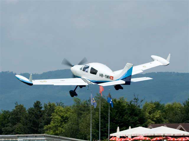
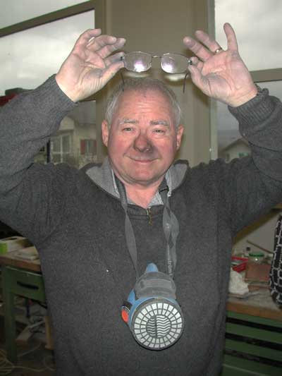
[July 12, 2007]
It is often the case that, once the answer to a question is known, one is tempted to see whether one could have arrived at it analytically.
Theory of Wing Sections (p. 195) gives a CL increment of 0.6 for a 20-degree-deflected plain flap. Assuming that because of the dropoff in the spanwise lift distribution near the tip the effective CL is only a third of the theoretical value, that gives 0.2 * 1.2 * 205 * .87 * q for the maximum rolling moment, where 0.2 is the CL increment, 1.2 is the area of the flapped portion of the tip, 205 is the distance in inches from the centroid of lift of the tip to the CG, .87 is the cosine of the dihedral angle, and q is the dynamic pressure, which is roughly 16 lb/sq ft at 70 kias (rotation speed) and 64 lb/sq ft at 140 kias (typical cruising speed). The rolling moments from a fully-deflected trimmer run roughly from 700 lb-in at the lower speed to 2700 lb-in at the higher.
The next question is: How do those values compare in magnitude with possible fuel imbalances? Using Loftsman's tank analyzing routine, I obtained the weights and spanwise centroids of fuel loads from empty to full and made the following graph, which shows the incremental effect of each unbalanced gallon of fuel:
Each wing can hold about 70 gallons of fuel. As fuel is added the CG of the fuel moves outward, and the space occupied by added fuel moves outward as well. Consequently, the moment contributed by each additional gallon increases much more rapidly when the tanks are nearly full. At cruising speed and full tanks, the trimmer can neutralize an imbalance of 2700/1200 or around 2.3 gallons; with a more typical fuel load of 40 gallons, however, the figure is nearly 7 gallons.
Analysis by Cmarc, using the inviscid option (which is somewhat unconservative, that is, optimistic) and fully-deflected ailerons, gives a rolling moment at 70 kias (close to the flaps-up stalling speed) of about 45,000 lb-in -- obviously sufficient to counteract any probable fuel imbalance. But it is also obvious that the effect of the roll trimmer is very small compared with that of the ailerons, and that an aileron trim tab would have been a more powerful roll trimming device. Duh.
[July 11, 2007]
I finally test flew the roll trim flap. The good news is that there is no noticeable adverse yaw or side force from full deflection; the bad news is that there is not much rolling moment either. At approach speed you can barely tell whether the flap is deflected or not. At 140 kias the effect is much more marked, but by the time you've reached altitude and accelerated to cruising speed the fuel imbalance that the trim is supposed to compensate for will probably have burned off anyway.
The flap travel is about +-20 degrees. I was interested to see that with the flap going downward, separation occurs at or slightly before half travel. The rolling moment continues to increase, but probably at a lower rate that it would if the flow remained attached. The hinge is in the upper surface; the lower surface has a well-faired radius at the joint, and it is possible that the flow over it remains attached up to a larger deflection; but I can't see that side from the cockpit.
It remains only to paint the flap and forget about it.
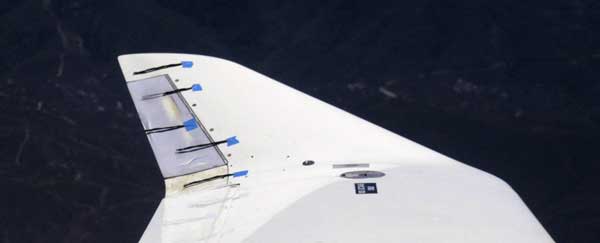
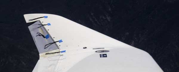
[June 29, 2007]
A correspondent (Frank Shoemaker) inquired about the kind of analysis needed for a modification like the addition of the trim flap. Another (Paul Lipps) wrote to point out that a spring trim on the stick works just as well, and is simpler than an electrically operated flap. I concede Lipps' point without debate.
How much analysis I would do would depend on the type of movable surface I was adding. In this case, it is a trailing-edge flap attached to a MAC servo. The servo is a linear jackscrew, and so the flap is locked in position at all times and is not susceptible to flutter. (Even if it came loose from the servo, I think that it is too small and light, and the wing is too massive and stiff, for mutual excitation to occur. That is just an intuitive judgment, however. The flap might buzz, or even tear itself off the wing.)
As far as stress analysis is concerned, I never did any stress analysis of the upturned tips in the first place. I considered it self-evident, based on experience with foam-cored structures, that they would be strong enough. They have a spanwise ply of unidirectional carbon in both upper and lower surfaces as well as the two-ply 45-degree glass torsion box. I also figured that even if one failed it would not be a safety of flight issue. After building them I tried to bend one and found it to be sufficiently stiff that in my opinion air loads would not break it at up to 200 knots (Vne).
One can, however, do a back-of-an-envelope stress analysis. Dynamic pressure at 200 knots is 132 lb/sq ft. CFD analysis of the spanwise lift distribution suggests that the tips achieve only about 60% of the CLmax of the wing at their root (BL 200), tapering to zero at the tip. With the trim flap set 20 degrees down I would very conservatively assume an average CL of 1.0 for the tip, which has an area of 1.6 sq. ft. Because the tip tapers from a root chord of 21 inches to a tip chord of only six, I would put the spanwise centroid of pressure 5 inches from the inboard end of the tip. This works out to a compressive load in the skin at the root of 1.6 * 132 * 5 / 3 (3 is the section depth in inches), or around 330 pounds. This root moment can be simulated with a 20-pound force applied (by hand) to the tip of the structure. Of course the moment curve is different; a concentrated load at the tip puts an unrealistically large bending moment at mid-span. But in any case this is a limit-load test, not ultimate.
The flap itself, which is piano-hinged along its entire leading edge, undergoes only torsional loads, for which it is manifestly adequate. I added a strong rib to the inboard end, with a nutplate where the actuator attachment goes, and bagged a two-ply layup over it to ensure shear continuity between the end rib and the skin. There is no rib at the outboard end.
In the process of adding the trim mechanism, I hollowed out some of the foam core at the root of the left tip; also, making the trailing edge into a movable flap interrupted the torque box. To remedy these defects, I closed out the cove, added a glass shear web where the foam now ends, closed the nose of the flap, and placed a four-ply reinforcement in the unsupported portion of the upper skin, which, as a thin curved compression member, is the most critical element in bending. The reinforcement also serves as an anchoring surface for the servo motor. Most of these modifications are in the aft portion of the tip, however, whereas the principal load is carried by the fore portion, which remained unchanged.
When putting a flap on a swept panel, you always have to choose between aligning the end gaps with the airstream and making them more or less normal to the trailing edge. The latter option avoids interferences, but I find it aesthetically unacceptable, and so I opted for the former, with the result that the end gaps have to be larger than I would like.
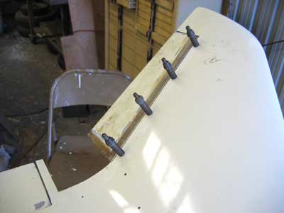
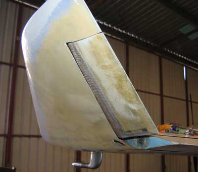
[June 24, 2007]
Having hacked up the left winglet in pursuit of the nonexistent pitot leak, I decided that I may as well put in the roll trimmer. This involved cutting up the winglet even more, but by now I was hardened to it. I have a little trim motor that I bought in 1987, and have been storing since then in a cool dry place, for this very purpose. The trimming surface is a flap on the winglet. Because the winglet has a 30-degree dihedral angle, the trim surface will actually produce some lateral force that will have to be neutralized by the rudder. Probably it will be too small to notice, and in any case the point of the trimmer is just to reduce the stick force due to a temporary fuel imbalance at the beginning of a flight. Imbalances occur mainly when the plane has been parked for a long time on a slanted surface, or one main gear strut is less fully inflated than the other. It's just been a minor and occasional annoyance up to now, but I can imagine that with more fuel that I usually take on, and the center of gravity of the fuel consequently farther outboard, it could be quite a nuisance. On the other hand, when I get around to moving the aileron hinges aft in order to provide more aerodynamic balance and reduce their hinge moments, an asymmetrical fuel load may not be such a problem.
[June 14, 2007]
I finally got the pitot-static sign-off today. Adjusting the transponder was not excessively expensive. The funny thing was that when we repeated the pitot test the pressure still bled down. Then it finally occurred to me to ask the technician to remove his test attachment from my pitot tube and put his thumb over the end of it and repeat the test. It still bled down. So the leak was in their equipment, not in my system.
[June 12, 2007]
Wrong. That was not the leak. Today, at first, I concluded that the leak must be in the pitot head itself. I extracted it from the wing with some difficulty and submerged it in water while pressurizing it with my dental gadget. A stream of bubbles rose from what turned out to be a drain hole that was clogged with something or other. I cleared the hole, and then when I covered it the pitot head held pressure. But it now seems as if the whole system is holding pressure, so something I did at some point in the last two days, I don't know what, must have sealed the mysterious tiny leak, wherever it was.
The radio shop, of course, has not yet even looked at my transponder.
[June 11, 2007]
It was surprisingly difficult to locate the leak. I tried pressurizing the system and painting all the joints with soapy water, to no avail. I broke the plumbing down into segments and tested them one by one, using a dental syringe (quite a handy thing, actually; you're supposed to squirt between your teeth with it, I suppose, but it just happens to generate 200 knots in the ASI when fully compressed) and an inches-of-water gauge that I had forgotten I had, but found in a cabinet while looking for a second ASI. I sawed out a chunk of the trailing edge of the left tip and dug out the blue foam stuffing to uncover the short length of vinyl hose that runs from the pitot tube to the 3/16-inch aluminum tube that connects the wingtip to the instrument panel. I finally concluded that the slow leak was where the vinyl tube slipped over the copper tube sticking out of the pitot, which is the standard heated type. I hope I'm right; if it's not there, I have no idea where else it could be.
[June 10, 2007]
I took the plane to the local radio shop for the biennial pitot/static certification, which is required even for VFR flying here because Whiteman is within 30 nm of LAX. The first problem that arose was a leak -- slow, but not slow enough -- in the pitot plumbing; the second was that the transponder's pulse timing had drifted off and was outside the tolerances for the test (the end result being that it transmitted inaccurate altitudes, even though the encoder was generating accurate ones). The radio guy who I hope will be able to fix the transponder was away for the week, and so we borrowed an AT50A from another airplane and completed the altimeter and encoder checks, which were fine. I'll find out Tuesday about the transponder -- I have a bad feeling the guy is going to say, "Can't fix it, you'll have to buy a new one, but here, we have a great deal for you." Meanwhile, I've been trying to track down the pitot leak. I have a feeling that it's where the tip extensions attach to the wing, which is bad, because I was uncharacteristically reckless there and made no provision for getting access to the pitot tube. Now I'm going to have to cut some holes in the tip to get at the thing, but I guess I can view this as a divine nudge toward installing roll trim, which an airplane with full-span fuel tanks needs.
[June 3, 2007]
I made round trips to Mendocino and to Paso Robles in the past week. Nancy was with me on the Mendocino trip, and she didn't find her seat, which used to be the pilot's seat, overly comfortable. I didn't love the new pilot's seat either. I decided that one problem was that the seat back was not sufficiently concave (about an axis parallel to my backbone), and so support was mainly being provided to the center of my back. I ground some more concavity into the seat back after that trip. It felt better on the hangar floor, but on the next trip, an hour-long flight to PRB, I felt that my back was getting sore again. By this time I was starting to wonder whether the whole business was not just my imagination, but I tried putting a lumbar support, which I unzipped from a little seat-cushion-plus-lumbar thingum that I had from Oregon Aero, behind me. That immediately felt a great deal better, and seemed pretty comfortable for the return trip -- or at least it allowed me to feel that the locus of dissatisfaction was now the seat bottom rather than the back.
I used to get a sore back (and shoulders) playing the piano. I wonder whether it's really that certain activities, among them flying and piano playing (for me, at least, and possibly for those who heard me play), produce muscle tension that is absent when, say, I am sitting in a movie theater or in an easy chair reading a book. Or, more likely, I am simply getting older, and more prone to aches and pains. I don't remember the seat being a major source of concern when Nancy and I flew for 15 hours from Alaska to Japan in 1976; and Melmoth 1's seats were much cruder than Melmoth 2's.
The trip to PRB was for Chuck Wentworth's annual barbecue at Antique Aero. A whole slew of interesting airplanes showed up, including, among the military types, a Zero, a couple of P-40s, a Sea Fury, and the expected herd of Mustangs. Most of these were extremely spiffily painted and polished, but the one I liked best looked somewhat war-weary, its aluminum dull and its paint chipped. It looked like the real thing.
[May 23, 2007]
Russ Hardwick and I flew to Page, AZ on the 21st to visit a couple of slot canyons. I had been working for the past week on the duct that leads air from the flush scoop on the right hand side to the controllable ventilator (from an '89 Camry) for the back seats. The duct is a fairly elaborate thing with a diffuser about a foot and a half long (a diffuser is a gradually expanding duct, intended to reduce the velocity of air flowing through it without allowing the flow to separate from the tunnel walls). At the end of the diffuser is a flow reverser that turns the air about 150 degrees and feeds it into the ventilator, which faces forward because the seats face aft. The reverser even has a turning vane in it; it's all very fancy.
When Russ and I left for Page, I hadn't yet tested the ventilator in flight and I didn't know how much air would come out of it. I did know that there was no way for people in the front seats to adjust the ventilator, but I figured that it was a warm day in LA and it was warm in Page, and so it wouldn't be a problem if it were open.
It was already apparent when we were taxiing that the ventilator was doing a pretty good job. It really went to town after we took off, discharging torrents of air into the cabin. This was not too objectionable at first, but then we climbed higher and higher to stay above the inversion and the turbulence, and the outside air got colder and colder. The ventilator happened to be aimed right between the two front seats. My right shoulder and Russ's left froze until we let down at Page. It's remarkable that a NACA scoop more than ten feet back from the nose of the airplane, where the boundary layer must be pretty thick, and behind the point of maximum fuselage width, can still pull in so much air.
[May 9, 2007]
I flew to Santa Ynez for lunch. The air was extremely calm -- groundspeed exactly matched true airspeed -- and I got a good speed point. Speed takes a very long time to settle down -- several minutes. As I have often mentioned before, I determine drag area (or drag coefficient -- they amount to the same thing) by comparing observed performance with computed performance, using the performance prediction routine in my lofting program, Loftsman. The computer output is one or two decimal points more precise than in-flight observation; for example, when my fuel flow indicator flickers back and forth between 6.9 and 7.0, I call it 6.95, but it could be any number within two or three hundredths of that. Airspeed can be measured within maybe half a knot, assuming zero calibration error. Here is the Loftsman output for a weight of 1,900 pounds, a density altitude of 10,400 feet, and a power setting of 26 in Hg and 2,000 rpm. The collective EGT was about 60 degrees lean of peak. Indicated airspeed was 133 knots.
The items, from left to right, are true and indicated airspeed in knots, drag in pounds, thrust horsepower required (a function of speed and drag), estimated propeller efficiency (based on a highly generalized curve), brake horsepower required (which is thrust horsepower required divided by propeller efficiency), percent of rated power, ratio of parasite to induced drag, engine specific fuel consumption (again based on a generalized curve), fuel flow in gallons per hour, specific range (that is, nautical miles per gallon), and, finally, the "CAFE" product of true airspeed and miles per gallon. The highlighted line corresponds to yesterday's measurement.
The last item, which I call the CAFE product because it was the crux of the scoring formula for the old CAFE efficiency races, is related to the "Carson speed", the speed at which you get the "best" combination of speed and efficiency (as distinct from the L/D or best range speed, at which you get the best efficiency, regardless of speed). The best speed to fly, on this basis, would have been closer to 140 kias.
Cylinder head temperatures, with the cowl flaps closed, were:
1.
175 C.
2. 170
3. 170
4. 170
5. 150
6. 180
On the return trip I used a slightly higher power setting (26.7/2,200, fuel flow 7.8 gph) and saw a somewhat different temperature distribution:
1.
185
2. 160
3. 180
4. 175
5. 150
6. 190
So the general pattern is: #1 and #6 are warmest, #5 (not #2, as I always thought) is coolest, and the others are somewhere in between. The previously observed coolestness of #2 correlated well with its being the first cylinder to reach peak EGT; it was therefore running leaner, and hence cooler, than the others. The present observation does not correlate with anything in particular, but suggests that the earlier pattern was just a coincidence. At this point the cooling is sufficiently well-behaved that I think I will just stop paying attention to it.
[May 8, 2007]
I realized yesterday that for years I have been referring to the left front cylinder as #5. It is #6. I went back and corrected the error all through this narrative (I hope).
What else have I been doing wrong for years?
Cylinders on my engine are numbered from back to front, with odd numbers on the right because the cylinders are staggered with the right side farther aft. (Multiple engines, on the other hand, when they are on the wings, are numbered from left to right, like freeway lanes.) My engine's oil cooler is mounted on the crankcase directly behind the #2 (left rear) cylinder.
The reason the lack of finning on the exhaust port surface is not a problem with downdraft cooling, I think, is that air emerges from the baffle passages at high velocity, and so heated air is continually scavenged from the unfinned surface. When the flow is going in the other direction, however, air converges into the baffle passages from a wide range of angles, and does not pick up a lot of speed until it enters the baffles. The revised baffle provides a converging channel over the exhaust port, and also adds baffling that wraps around the undersides of the cylinder, increasing the velocity of airflow there.
[May 5, 2007]
Success again. I redid the baffles on the right rear cylinder (which modification took three days rather than the expected one) and pulled its temps down by 50 degrees F or so as well.
Yesterday was a peculiar-looking day, with a shelf of dense clouds over the San Fernando Valley but lots of clear areas to the west. I started a 1,000-fpm climb westward once I was out from under Burbank's Class C. The CHTs were running around 150 C with the cowl flaps fully open. I closed down the aft vents to half an inch or so and went up to 10,500 feet without the hottest cylinders getting above 200 C. The target (ie factory recommended) temperature is 370 F or about 185-190 C. Continuing westward, I set up 27/2300, or around 55% (8.2 gph). With the cowl flaps closed as far as they would go (1/4-inch gap at the aft ends) the temps settled at around 150-175 C. (Different cylinders are still at different temperatures.) The oil temperature is still a rather high 97 C.
Incidentally, the reason I keep bouncing back and forth between Celsius and Fahrenheit is that my CHT gauge is calibrated in Celsius, while Continental's documentation is in Fahrenheit.
The #2 cylinder, the one next to the oil cooler, is still the coldest, and #1 and #6 are still the hottest, , but the disparities are much reduced. I guess that further tinkering with the baffling could bring the CHTs still closer to one another, but I'm not sure it would matter.
After pointing westward for a while I checked the GPS groundspeed and found that I was doing 90 knots. So I turned around, and then I was doing 220. Too bad I wasn't going to Arizona.
Success. The revised baffling on left front cylinder brought the temperature down by about 50 deg. F; it is now in line, +-20 degrees, with all the other cylinders save one, the right rear, to which I should be able to apply the same treatment next week. The problem with the cylinder is that it has no finning to speak of in the vicinity of the exhaust port:
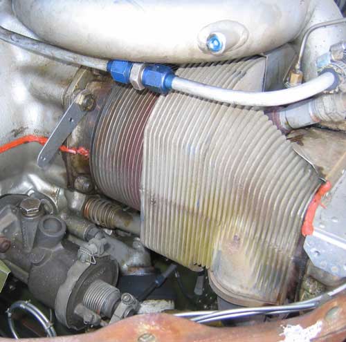
My baffles previously ended even with the centerline of the cylinder; the trouble with that arrangement, as I now see it, was that it did not provde enough air velocity, and therefore heat transport, on the lower half of the cylinder. I modified the baffles by extending them down around the bottom of the barrel and the inboard part of the head, and providing a barrier about 3/4 of an inch away from the finless portion of the casting around the exhaust port. The revised baffle looks like this:
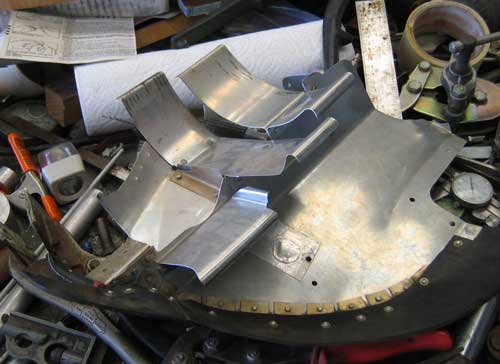
The way in which the baffle, which is lying down on my junkheap of a work table with its lower edge to the right, matches the cylinder should be fairly clear. I'm sure that still more improvement is possible -- the barrier near the exhaust port is pretty crude -- but this went a long way. Here's the way it looks installed:
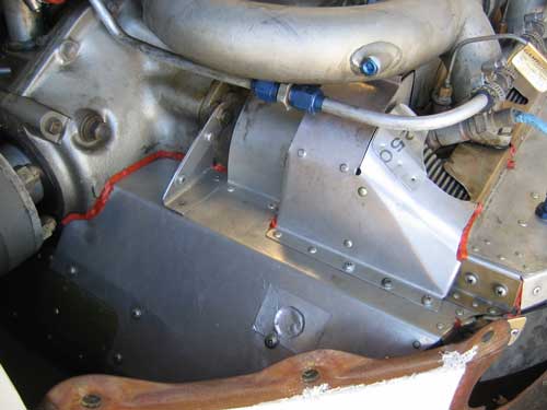
[April 24, 2007]
It finally occurred to me -- showing that if I think about something long enough, even the most obvious fact about it will eventually become apparent -- that what my two hottest cylinders, the left front and right rear, have in common with one another is that their exhaust ports are not next to another cylinder. The suggestion is that whatever flow guidance is provided by a neighboring cylinder for cooling air passing by the exposed side of the port, which has practically no finning, is not being provided by my baffles. This clue at least gives me something to work with.
I should have the flap actuator plumbing finished by the end of this week and be able to resume working on the synchronising cylinders. It's increasingly clear that I won't have the flaps working by Oshkosh -- my somewhat arbitrary target -- unless some phase of the project proves less, rather than more, time-consuming than expected. That would be unprecedented, however. Well, maybe they'll be working -- but only on the ground.
[April 17, 2007]
The NACA scoop for back seat ventilation works nicely. I tufted the inside of the fuselage behind it, and the tufts were straight and steady in flight, indicating a strong flow with little turbulence. What I want to do now is diffuse it over a distance of about two feet and turn it around 180 degrees toward the back seats (which face aft). I sat in the new pilot's seat for this flight; it's not right yet. More foam grinding ahead. Cruised around for half an hour making squiggles on the GPS map. 137 kias at 7,500 ft DA, 7.6 gph -- a bit below par. It's interesting to note that opening the cowl flaps about 1/2 inch pulls CHTs down by 40 deg F, but does not have a measurable effect on speed. Tomorrow I think I'll wash the plane -- it's embarrassingly dusty -- and then get back to the flap hydraulics.
[April 13, 2007]
Two weeks later and I'm still installing hydraulic lines. It's weirdly time-consuming, to say nothing of expensive (AN and Aeroquip fittings are not being given away these days, unfortunately), but I'm getting there. I took a short detour this past week to cut a Concorde-shaped hole in the right side of the fuselage for an air vent for the back seats. I haven't flown yet to see whether any air actually comes in through it. It's one of those flush NASA affairs, and it's hard to understand how it can work very well once the boundary layer has grown to a depth that's comparable to that of the inlet channel. I'll test it on Monday.
I've also been grinding away at the foam on the pilot's seat and then sitting on it for a minute or two to see how it feels. It's hard to judge; even park benches feel comfortable at first.
[March 31, 2007]
Something about me seems to be extremely irritating to upholsterers. On Friday I was shown the door by the second one. I was not heartbroken; he seemed to me to be even less conscientious and competent than the first, who was no great shakes. But at least I ended up with a bunch of foam, glued rather haphazardly to the seat frame, at no charge. It's just as well that he decided to kick me out before he covered the seats, because the way he had shaped the foam was not very comfortable anyway. I'm going to try my hand at it, imitating the seats in my Geo Prism, which seem fairly comfortable.
In the meanwhile I've been adding the plumbing to deliver hydraulic fluid to the outboard flap actuators, and thinking a lot about an alternative cooling air intake configuration that might make it easier to equalize temperature among the cylinders. Just thinking; there are plenty of other things to work on first. But it's something to do while going to sleep.
Here's the environment of the outboard actuator:
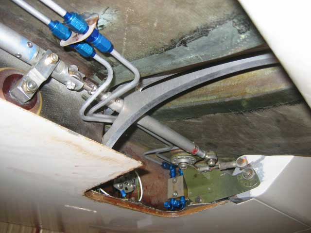
The flap has been lowered to reveal the cove just inboard of the aileron; the latter can be seen, deflected upward, in the lower right corner. The diagonal pushrod is the aileron actuator, supported, in the upper left corner, by one of several idlers. An inspection plate has been removed, revealing the outboard fuel quantity sender (partially in shadow) and an aluminum block (bottom center) with blue fittings protruding from its top and bottom. The purpose of the block is to provide an anchor for the ends of flexible hoses going to the actuator, which will be installed just outboard of the aluminum flap track, between it and the fuel quantity transmitter. The paired lines, which run about ten feet inboard to the fuselage, are what I've been installing; they are 3/16 inch in diameter, and are secured to the upper surface of the cover at 15-inch intervals by tiny phenolic pillow-blocks.
[March 14, 2007]
I flew for half an hour to test the effect of the exhaust pipe insulation on the temperature of the left front (#6) cylinder head. It went up. This was not entirely unexpected; the exhaust pipe is in intimate contact with the cylinder head, and if stays hotter because of the insulation, some of that heat would migrate into the head. It was a question of whether the benefit of not preheating the air approaching the cylinder baffles would outweigh the ill effect of keeping the pipe hotter. It didn't.
A speed point -- density altitude 10,000 ft., weight 1950 lbs, fuel flow 7.5 gph, IAS 138.5 kts -- confirms once again the value of 2.25 sq. ft. for F.
I took my pilot's seat to the tapiceria -- upholstery shop -- across the street from Whiteman for an estimate. The amiable and copiously tatooed owner said it would be around $200 to do the second one -- $150 labor and $45 for the foam. I already have the covering material from my unhappy episode with the uphostery guy on the airport, who wanted half again as much money for the same job and then did it badly.
[March 12, 2007]
It was 90 degrees today, but there was a good breeze at the airport and for some reason the metal hangar does not become unbearable on hot days. Neddy, my large, long-haired and black dog, seemed pretty comfortable sprawled on the asphalt. I did some laminating in the back of the plane and noticed that for the first time this year I had to take care not to drip sweat on the epoxy-soaked glass cloth. The anchorages for the inboard flap actuators are now in place, and I have nearly finished making the hard points that will be secured near the outboard ends of the flaps to anchor the flexible hoses going to the actuators. Once those are in place, I will be able to plumb the hydraulic lines from the fuselage to the outboard actuators, and then get on with the synchronizer. On Friday, tired of fiddling with the flaps, I wrapped the exhaust pipe below the left front cylinder with insulating stuff, but I have not yet flown the plane to determine whether the proximity of the pipe is actually the reason for that cylinder running hotter than its neighbors.
[February 28, 2007]
I spent a jolly hour or two on my knees in the back of the plane, sanding out clearance for the flap actuator, which passes though a couple of bulkheads in a very confined space. At first I tried to do it with files, rasps and sandpaper, and I reminded myself of those patient prisoners who break out by filing their way though steel bars with dental floss dipped in floor dust. I then had the inspiration to saw a slot in a piece of 3/8" aluminum rod and slip the end of a 20-year-old, and hence tightly curled-up, piece of 40-grip Norton abrasive cloth in it. This, chucked in an electric drill, cut through fiberglass and plywood beautifully. At the end of an unusually long afternoon I had the left actuator working without interference though its entire travel. The right one will be easier because now I know what needs to be done, but harder because I'm right handed, and it's on the wrong side for holding a drill motor while hunched up on my knees.
[February 27, 2007]
I
went to get some O-rings at A.C. DePuydt, Inc. I
love that place. It's located in an LA suburb with the arresting name
of Commerce. You go to the Will Call counter with your tiny order for a
dozen rings. They always have what you want, even weird sizes without
AN or MIL numbers, and after they're pulled it from inventory they send
you around to the cashier, who is always charming, and in no time the
invoice has been typed up and you're out the door with a little brown
paper bag in your hand. This time the bill was $5.14. I think they have
a $5 minimum; they give you extra O-rings to fill in the gap. I took
them to the hangar, where a bunch of hydraulic cylinder parts that I'd
made over the past couple of weeks were waiting for them.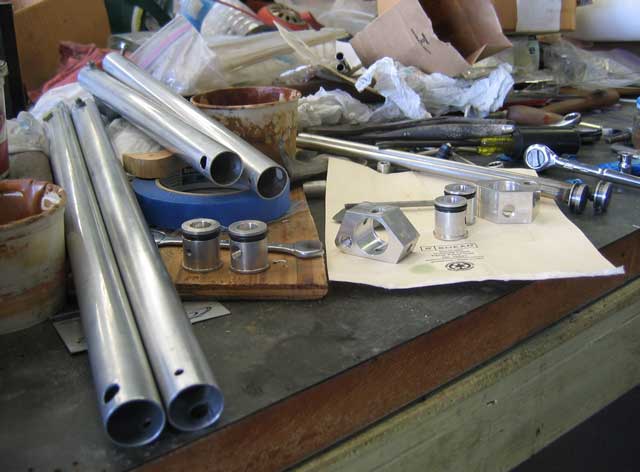
I started to assemble the four hydraulic cylinders that will operate the flaps. I found that the silver-soldered joints between the shafts and the pistons for the outboard cylinders were leaky -- I submerged them in water and applied compressed air to the hollow shafts -- and I'll need to put some epoxy inside. On the inboard cylinders I had threaded the shafts and the pistons and used penetrating threadlocker, on the advice of my machinist friend Homer Knapp. They came out without any leaks. I then tried to assemble the cylinders and found that on one of them the hole in the end plug through which the shaft emerges was too small for the shaft. The shaft, which is a piece of surplus stainless tubing that I picked up at Industrial Metal Supply, mics at .378, and I've been reaming the bores with a .377 reamer. To enlarge the reamer I used another Homer trick, namely sliding a hard steel edge along the front of the flutes, which I suppose must raise a tiny burr. After I had done this several times the shaft finally passed and I was able to assemble the cylinders, one of which see below. The overall length of the cylinder in its retracted position is 20 inches. The next step is to fit them to the airplane, which I will do tomorrow -- or at least start doing tomorrow.
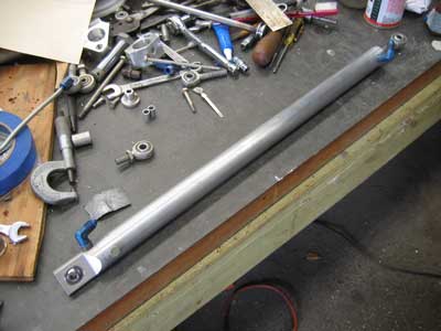
[February 21, 2007]
Machining, machining. The four actuating cylinders for the flaps are almost ready, and the synchronizing cylinders are about halfway there.
In the meantime, about three weeks ago I had delivered the structure for the fourth seat -- which was to be the pilot's seat -- to the upholstery shop on the airport. I took the guy the first seat he had done for me last fall and asked him to duplicate it, except that I wanted the seat cushion to be about an inch thicker and that there be more of a lumbar support at the bottom of the seat back. Several weeks passed, and then he presented me with a seat which was indeed one inch thicker, but only right under the buttocks, so that sitting on it was something like sitting on a watermelon: no thigh support, no lateral support. The lumbar bulge seemed to extend the whole height of the seat back, which was now flat rather than slightly concave as it should be. After one flight to see what it felt like, I took it back to him and pointed out that the first seat he had made was comfortable and well-formed -- so he obviously knew how to make a seat, which is, after all, what he does for a living -- but the new one wasn't. First he explained to me that this was my fault, because I hadn't had him make both seats at once -- although if I had, I would then have had two seats that were too low and lacked lumbar support, rather than just one. After some more discussion, he said, "All right, come back in an hour." I couldn't do that, but I came back the next day only to find that his knickers had evidently gotten into such a knot that he had stripped all the upholstery and padding from the seat frame, and refused to have anything more to do with it.
Well, I never liked the guy much anyway.
[February 10, 2007]
I spent the past week machining parts for hydraulic cylinders, averaging one mistake per three parts, and planning just how this flap system is going to fit in the airplane, how many of which kind of AN fittings it will require, and how the hydraulic connections will be bled. In Melmoth 1, which used two hydraulic flap actuators, one driven by the exhaust of the other, I used a kind of settling tower, consisting of a cylindrical fuel filter bereft of its innards and mounted upside-down, to capture air in the line connecting the two cylinders. I replenished the hydraulic fluid in the trap at fairly regular intervals, but never did know where all the air was coming from. The system for Melmoth 2 would require four such traps, one for each of the lines connecting the master cylinders to the flap actuators. I'll see how it works without them before installing them; the system, without air traps, works beautifully in my imagination.
Early in the week I also overhauled the left main gear strut for the second time. I had done so a few months ago, but it soon resumed leaking hydraulic fluid like mad. It turned out to have a rolled O-ring, due, I think, to an area of corrosion on the bottom of the groove which must have developed during the struts' many years of idleness. I bought the two Cherokee gear struts (whose outer shape was heavily modified for this airplane, but their inner workings are untouched) quite early in the project, back in the early 1980s, and they proceeded to sit around, along with the engine, for twenty years. I was able to clean up the rough area with fine sandpaper and the tip of my pinkie, but until I've made a few landings I won't be sure it's really fixed. The left strut also leaked air for the first year or so after the airplane flew, and then finally sealed itself up; that leak was up top -- as a general principle, air leaks out the top, fluid out the bottom -- and I have no idea what made it go away, other than the mysterious force that seals some leaks over time while it makes others worse. The right main, on the other hand, has been perfect, requiring neither fluid nor air in more than four years of operation.
[January 31, 2007]
The age of miracles is not over. I managed to connect the hydraulic flap control valve to the plumbing leading aft without taking the whole plane apart. I had to grind a 9/16" crow's-foot wrench down to a wisp, but it worked. One of the lines I installed was a remnant from Melmoth 1; I like incorporating little bits and pieces of the old plane in this one.
The two pictures below show the plumbing that is now complete. The upper one is particularly confusing. It is taken from beneath the airplane with the airbrake open and the cover that usually separates this area from the cockpit removed. The top of the picture is forward; the blue corrugated surface in the background is the hangar ceiling.
There are three physically identical valves in the picture (how many monkeys are hiding in the forest?). The one in the center, which controls the landing gears, is closest to the camera and looks larger than the others, but it is the same size and shape as the one in the upper left hand corner (airbrake) and the one at top center in the background (flap). My great accomplishment of the past two days has been to install the two vertical lines that run from the flap valve down to fittings below the main spar, which is the black object running across the bottom of the picture. For scale, the lines are 1/4-inch. Anyone who has done mechanical work will wince at the thought of tightening the nuts on the flap valve.
The valves are operated by cables running through Teflon-lined bicycle-brake-cable housings to the panel. One cable is visible in the groove in the capstan on the landing gear valve in the center foreground. The cylindrical white object just above the main spar is the hydraulic cylinder driving the landing gear. This whole mess is located under the front passenger's seat.
The picture below shows the same area, but viewed from behind the main spar, so that the continuation of the flap plumbing into the right main wheel well can be seen. The two 1/4" lines coming from the airbrake compartment pass below the main spar and are reduced to 3/16". They run above the gear when it is retracted, and down the rear spar. They pass below it to reach the compartment below the rear seats, where the flap synchonization system will be located (along with the oxygen bottle). The white rod is part of the gear retraction system. In addition to the right main gear, it is connected to a bellcrank that rotates a torque tube linking the nose gear to the mains.
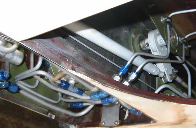
[January 28, 2007]
I'm finally working in earnest on the flaps.
The first step is to provide plumbing from the control valve, which is in place, to the compartment under the back seats where the synchronization system (see January 8, 2005 -- time flies!) will be mounted, and from there to the outboard actuators in the wings. I improvise these things as I go along, and I found myself in a jam with respect to the lines going out along the wings. It happens that the roller tracks embedded in the fuselage sides and the plates to which the rollers and the inboard ends of the flaps are attached combine to eliminate any practical passage, even for two little 3/16" hydraulic lines, from the wing into the fuselage. It now appears that the solution will be to pass the lines forward through the rear spar outboard of the main landing gear, follow the front side of the rear spar to a point inside the fuselage, and then run aft underneath the rear spar -- there's about an inch between the bottom of the spar and the bottom of the fuselage -- into the compartment.
I have already made the mounts for the outboard actuators (see December 4, 2004) and have begun the mounts for the inboard ones. The outboard actuators are ready to install, but I have not yet made all the parts for the inboard ones. Nor have I finished machining the master cylinders. I also need to make new center tracks, and I'm not yet quite firm on their design. There's quite a lot to do.
[January 15, 2007]
I feel irritated with myself for spending time on something as stupid as this exhaust pipe fairing when I should be working on the flaps. The fairing is almost done. Viz:
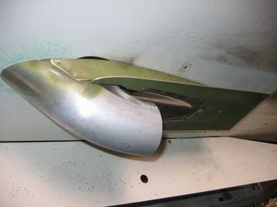
The aluminum cuff will be trimmed for clearance; when the picture was taken it was still untrimmed in order to help with alignment. I'm a little concerned that I haven't left enough clearance for the pipe, which bounces around, mostly sideways, on startup and shutdown. The fairing has some freedom of motion, however, to allow it to accommodate itself to the pipe. When this is done I definitely have to work on the flap and nothing else.
The other day I flew to Reno with Javier Arango in his CJ2. I have a GI bill Learjet rating of ancient vintage, but I seldom get to fly in a jet. It's a different world. Noise-canceling headsets create a tombal silence in an already quiet airplane. Almost everything is done by twiddling knobs; it's something like operating a very complicated elevator. Javier mentioned having installed a new engine in his Bonanza and the throttle linkage coming loose in flight five hours later. The engine went to full throttle (note to self -- put a full-throttle spring on M2) and he landed by modulating power with mixture. Good presence of mind.
A few days after our trip a CJ crashed on takeoff at Van Nuys, killing both pilots aboard.
[January 3, 2007]
After an unaccustomed five days without going to the airport, I finished the structure of the fourth seat yesterday and today. Tomorrow I'll take it to the upholsterer. I installed the mic and phone hookups for the back seats a couple of weeks ago; the only thing missing back there now is ventilation. As long as it's winter, that's not too urgent.
I started work on a fairing for the exhaust pipe, the main purpose of which is to keep the boundary layer more or less intact between the airplane and the exhaust stream.
I happened to stumble on an RV discussion group online, where someone had inquired about the pros and cons of "slapping" a turbocharger onto his engine. Most of the response was negative, predicting all kinds of dire consequences -- overheating, cylinder wear, valve trouble, even flutter (because flutter is a function of true, not indicated, airspeed). I was reminded of the years that I spent worrying about all the terrible things that might happen if I turbocharged my engine. I finally did so, and have never regretted it. For me the turbocharger is not so much a matter of higher cruising speeds at altitude, though that's sometimes nice; it's more about rate of climb. True, I did once have to land on a road when a turbo lubricating oil fitting broke; but that was a bad fitting, not a more general engine problem. I don't run excessively high power settings, cooling is not a problem, fuel consumption on a per mile basis is lower (because I'm going faster and still leaning to between 50 and 75 degrees lean of peak), and I can maintain a steady 1,000-fpm rate of climb up 12,000 feet, where I like to cruise. All this might be different, I admit, if I were trying to cruise at 75% power at 24,000 feet, and that may be what people are dreaming about when they inquire about turbocharging their homebuilts.
[December 20, 2006]
In the current issue of Flying (January, 2007) I mention an interesting paper by a former Naval Academy professor, Bernard H. Carson. A reader kindly sent me an electronic copy of it, which can be downloaded here. It is in the public domain, and may (and should) be distributed and reproduced at will.
[December 16, 2006]
I spent the week working on the structure for the fourth seat. Very dull stuff. Daydreaming while working, I happened upon the nettlesome topic of the airplane's parasite drag coefficient, which hovers at around .021. There are still a few things I can do to reduce drag, but I doubt I will be able to reduce that number by much. How do some airplanes manage to get down to .016? The answer, I realized (again, since I have realized this many times before and then let it slip my mind), in at least some cases, is in the relative sizes of wing and fuselage. The P-51, for example, has a small, slender fuselage compared to its wing. The Bellanca Skyrocket has a conventional, Mooney-, Bonanza- or Comanche-like relationship between wing size and fuselage size. Melmolth 2, however, has a relatively large fuselage and an abnormally small wing -- 104 square feet as against 170-180 for most factory-built four-seaters. Since parasite drag coefficient is referenced to wing area, while the fuselage contributes disproportionately to parasite drag, an airplane proportioned like Melmoth 2 ends up with a higher parasite drag coefficient than its actual cleanness deserves. Or at least that is what I would like to think.
[December 4, 2006]
Went up to Reno to talk with Richard Tracy about the Aerion, a supersonic (Mach 1.6) business jet that's under development. It's 140 feet long, seats 6 or 8 in lounge-like comfort, and is supposed to cost $80 million a copy. I don't have a whole lot of sympathy with the need of Fortune 500 executives, who are already far more lavishly rewarded than they could possibly deserve, to shave three hours off a golfing trip to Scotland; but at least the scheme is, as Oppenheimer said of the atomic bomb, "technically sweet," and Tracy is such a nice guy he makes you feel that everything is fine. On the return flight I squeezed back into Whiteman just in time; M2 still has no lights. The moon rose over the southern Sierra as the sun was setting into the Pacific -- one of those transfixing moments that are worth all the work that goes before.
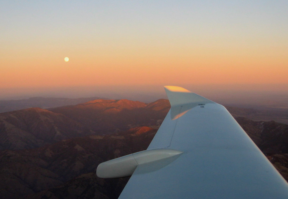
[November 17, 2006]
Flew to Camarillo with two passengers. This was the first flight with a human being -- a woman whose weight I estimate (being, to be sure, no great estimator of women's weights) as 140 lbs -- in the back seat, but since I had carried greater weights back there before, it was not exactly a test flight. CG was around 28% of chord. Anyway, she liked the view.
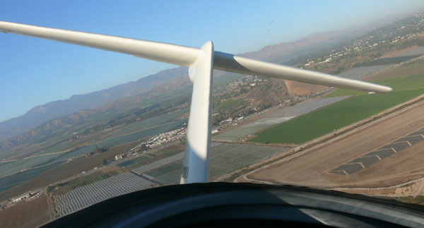
[November 16, 2006]
Flew to Torrance to talk with Bob Archer, antenna guru, about how to improve on my VOR antenna without increasing drag. Archer sells some strangely-shaped antennas that fit into composite wingtips, but my wingtips are too small for them unless, as he suggested, one were to replace the longest element in the antenna, a strip that runs straight backward for about 20 inches, with a screw-in rod that one would remove when the airplane was parked where some hapless pedestrian was likely to bump into a long, inconspicuous protrusion. An alternative was to embed a quarter-wave dipole in the leading edge of the horizontal tail. The spar is carbon, but is far enough from the leading edge to act as a reflector. The result would be an antenna with good sensitivity forward and poor sensitivity to the rear. If you have sufficiently good sensitivity forward you don't really need terrific sensitivity to the rear, but such deficiencies as the horizontal tail antenna may have could be supplied by one in the wingtip.
I put some fuel into the airplane before the flight, and a few minutes after takeoff, and shortly after turning on the automatic fuel tank switcher, I noticed that the tank cap was missing from the right wing. This was the first time in my life that I have taken off with an unsecured fuel cap -- I once left an oil cap off, back in the '70s -- and I was doubly fortunate: that I did not attempt to take off using the right tank, since suction on the filler opening could have interfered with fuel flow after rotation, and that the automatic switcher did not go to that tank while I was flying over Los Angeles. I don't know whether upper-surface suction could have interfered with fuel flow (one could calculate this fairly easily, comparing upper-surface pressure with the head of fuel in the tank), but I would not care to find out the hard way. It's surprising, and instructive, that I could have overlooked the tank cap lying right there on top of the wing -- I retrieved it later from the airport office -- and that I had never before even reflected on the safety issues -- if any -- that an open tank might entail.
[November 15, 2006]
Flew out to Mojave. The not-loud-enough theory was correct. Without the earplugs, the intercom is fine.
I caught a glimpse through a partly open door of parts for the next White Knight being made in Scaled's huge new hangar. The wingspan will be over 150 feet, I believe. SpaceShipTwo will carry six passengers and two crew and go somewhat higher than SpaceShipOne did. I'm still wondering whether suborbital "space tourism" will catch on. I imagine elderly members of the overcompensated classes staggering out of SpaceShipTwo, covered with barf and white as a sheet, and muttering, "That was great!"
[November 7, 2006]
The intercom works fine, at least on the ground, with the radio on. My latest theory is that it just isn't loud enough. I use earplugs underneath my headset, and it's possible that the intercom simply isn't as loud as the radios and the earplugs are blocking it out. In Melmoth 1 I used to use a Plantronics with earplugs that had holes punched in them and slender plastic tubes glued in to conduct sound. That might solve the problem, but in the meantime I'll just try flying without the earplugs. After all, I don't wear suspenders either.
[November 6, 2006]
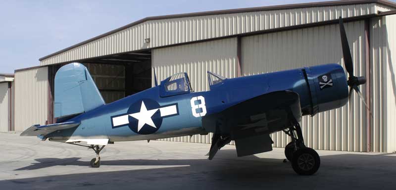
I flew up to Paso Robles today to take a ride in Javier Arango's Corsair. I sat in back and couldn't see the instrument panel, so I don't have a very nuanced sense of what was going on. The acceleration on takeoff was like a jet's -- the airplane is 1,000 pounds lighter than it was with armor, armament, and military radios, and it cranks up 55 inches for takeoff. It climbs rapidly, as befits an airplane with a low wing loading -- not too different from a Bonanza's -- and a very low power loading. Chuck Wentworth, whose restoration business Antique Aero is at PRB and who maintains Javier's fleet of planes, said that there are only about ten Corsairs left that are in flying condition or could be brought to flying condition without major work.
Javier owns an original Sopwith Camel -- they're really rare -- and I sat in it. It fits like a too-tight shoe. The fuel is in a pressurized tank right behind you, the open stacks of the engine are spitting fire about four feet in front of you, and there's barely room to turn your head. Javier thinks that the seat back bulkhead was installed at the wrong station during one of the airplane's many trips to the repair shop; it was used for training, and crashed on takeoff with regularity. I cannot fathom going out to get shot at in such a thing; it's scary just to sit in.
The intercom in Melmoth continues to be a puzzle. It works on the ground, but not in the air. It occurred to me today, while I was driving home, that it could be that turning on the comm radio interferes with it; I'll check that tomorrow.
[October 25, 2006]
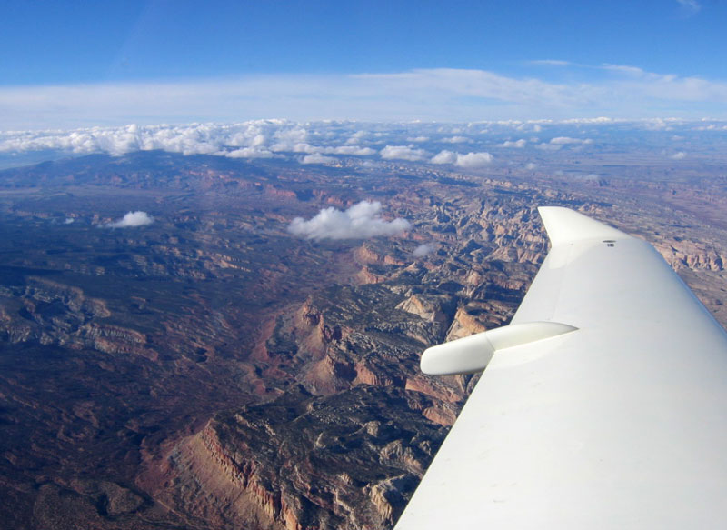
Apparently I didn't do a very good job of checking out the intercom, because it didn't work at all during the trip. My final adjustments must have had the opposite of the intended result, or else that one final wire made one thing work and another not. No matter; I'll fix it. The autopilot and the GPS tracker seemed to work, but from time to time one or the other -- I could never tell which -- would do something goofy; just enough to make you feel nervous when you're reading a map. Actually, the plane isn't bad to hand-fly in smooth air; but with turbulence the high stick forces in roll get tiring.
The trip was actually a failure in one sense, because a couple of weather systems got into complicity against us, and, operating under a VFR-only rule, we ended up leaving the plane in Denver in order to be sure to get to Providence in time for our daughter's college's "Parents' Weekend." But in another sense it was successful, because at its end Nancy did not say, "I never want to ride in this airplane again." Actually, the Airbus from Boston to Denver was worse. Whoever invented row 24 in an A319 should be made to sit in it for all eternity.
The cowl flaps worked very well; it was possible to control cylinder head temperature very delicately, regardless of speed and power. Performance was consistent with my current drag estimates; one point I noted was 180 knots at 9 gph at 14,000 ft d.a.; that's 60% of power. The plane used one quart of oil in 11 hours. On the negative side, the VOR antenna is very inadequate, essentially unusable at more than 40 miles; and the new pilot's seat was just okay, not miraculously comfortable as I had hoped it would be. There's always something to fix or change -- fortunately.
[October 14, 2006]
The intercom was a two-day puzzle, until I consulted the 30-year-old Collins audio panel installation diagram and found that it called for one more wire than the Sigtronics schematic seemed to require. Once I installed that, it worked fine; my first eBay experience is, so far, a happy one. I opened up the turn coodinator/autopilot to find out what the screw can have been touching, and I found nothing; so I wonder now whether the screw was really the problem at all, or just pretending. It seems to be working at the moment, anyway.
Leaving tomorrow for Boston, VFR.
[October 9, 2006]
Having concluded finally that my autopilot, which had been intermittent, was really not working, I took it to a local avionics shop where they bench checked it. It was working fine after all. I had already checked the wire harness for continuity, and so suspicion now fell on the servomotor. The shop lent me an overhauled autopilot (the autopilot circuitry is contained within the turn coodinator), which I plugged in, while holding it in my hand, with the panel opened up and my own unit removed. Everything now worked, including the servo. I then hooked up my own unit and found to my surprise that it ran fine. So I reinstalled it, only to find that once it was screwed into the panel it no longer worked. It took another half hour of swapping and testing to determine that the cause of the trouble was the upper left mounting screw. Although it was well under the 5/8" maximum length specified by a label on the case, it was evidently interfering with something inside. I cut another 1/8" from it, and the autopilot then worked fine. I still need to take the turn coordinator out once again and open it up to find out what the screw was touching.
It's very handy that the panel is hinged at the centerline and swings out for maintenance.
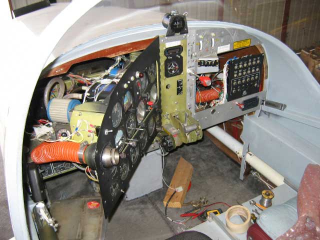
[September 27, 2006]
Today brought both my upholstered pilot's seat and, finally, an under-$80 intercom from eBay. The seat is a little disappointing; the cushion is thicker and softer, as hoped, but there is not enough lumbar support. It may be possible to change this, since the upholstery of the seat back seems to slide on like a slipcover and Velcro shut at the bottom. I also need to revise the brackets that attach the back to the pan, because the padding on the back is so thick that the pan is not so long as I intended it to be.
I was becoming discouraged about the intercoms, having lost several to other bidders, and so I had bids running on four of them at once. I lost one, won the second, and now, as luck may choose to have it, I'll probably end up with the other two as well. In the meantime I creep ever closer to a final decision about the back seat ventilation. A correspondent pointed out that an intake low on the left side would present some risk of ingesting exhaust gases, but I realized today that since my oxygen bottle is going to be under the back seats rather than under the rear seats' footrest, some of the space under the footrest can be used for a duct carrying air from a single right-side inlet over to the left side.
[September 23, 2006]
I still haven't done anything about ventilation for the back seats. I've more or less decided that the best inlet location is on the side, just below the top of the armrest, to minimize the amount of ducting required. But I've also been fiddling with sealing the window frames, which are probably the source of most of the high-frequency noise in the cockpit. They are also the source of ventilation, however, since in order for air to come in, it has to have a place to go out, and the rate of air movement, given a certain set of ducts, is going to be some function of the pressure difference between inlet and outlet. Of all the places where cabin air could leak out, the highest-velocity, lowest-pressure region is that around the front and top edges of the windows.
Contrary to intuition, air does not just naturally come in the front and go out the back; in fact, John Thorp put the ventilation inlet on the T-18 on the back end of the canopy, where the pressure is higher than inside. On the assumption that the best places to exhaust air would be those where the pressure is lowest, I considered two options: the top of the canopy and the side of the fuselage just above the wing. The pressure near the wing, at about 55% of chord, turns out to be more than 50% lower than that at the best point on the canopy top, and that location would be easier to protect against rain and to soundproof as well. At the moment, it's the leading contender.
[September 19, 2006]
The structure of the pilot's seat is at the upholstery shop and the job is supposed to be done by next Monday. Meanwhile I've been trying to make some progress on the flap actuating cylinders. I ruined one of them in a lathe today; fortunately I had made five and need only four. Now I can't permit myself any more mistakes on the cylinders, but I am still free to ruin one piston and one cap.
I've been bidding on intercoms on eBay; so far I haven't snagged one. Trying to figure out how to get a little extra money, I reflected that I could sell my DME and ADF, which I have not installed in the plane, on eBay for a couple of thousand dollars; but then I wondered whether I would regret that if at some future time I wanted to install one or both. With GPS they seem a bit outdated, but they are IFR legal, and my handheld GPS is not. I was thinking about selling my magnesyn remote compass and inverter, too -- genuine World War II equipment, but they took Nancy and me to Europe and Japan -- but then I remembered that the sensor/transmitter, which was mounted in the tail cone, was chewed up by the propeller of the Cessna that destroyed Melmoth 1.
[September 13, 2006]
Sometimes the maintenance gods are kind. The encoder is in and working perfectly, the left main gear strut has new O-rings, and I talked today with an interiors guy about finishing off my new pilot's seat. The problem with the autopilot was just a bad connection at the servo. Not bad for five days, including a weekend.
[September 8, 2006]
Some time has passed. Nancy and I have just returned from a three-week trip to the east coast, where we left our daughter Lily at college. We are planning to go back in October to visit, this time in Melmoth 2. This is noteworthy, because Nancy, although she flew all over the world in Melmoth 1 (see Two Mike Uniform), has never even sat in Melmoth 2, let alone left the ground in it. She was never fond of flying, but I attributed this particular reluctance to a feeling that she needed to be sure that Lily was properly launched before risking her own life again in one of my contraptions.
While vacationing I worked a little on some design ideas. I sketched a controllable wastegate -- I am now using the fixed type, from a Turbo Arrow -- and thought about how best to provide ventilation for back seat passengers. I decided on a couple of NACA scoops low on the sides, because they would keep the internal ducting to a minimum. Before leaving, I hooked up an intercom that I had made from a kit twenty years or so ago, but it didn't work. I'm now scouting eBay for one that does.
I realized back in August that the failure of the cowl flaps to close completely was probably due to deformation of the cowl top under air loads, and would not be fixed by a spring; what it really needs is for the closing limit switch to be touched by the cowl flap itself rather than by the actuator. The oil temperature rises by about ten degrees Celsius when the cowl flaps are closed, so they are doing something. My encoder failed just before we left, and since returning I've been busy installing a new one; it has yet to be tested (a new pitot-static calibration is required, since my airport is within the 30-nm veil of LAX). Various other service obligations loom, including a leaky left main gear strut O-ring. Fortunately the strut drops out of the airplane pretty easily. At some point I also have to remove the right wing to deal with a fuel leak in it. The leak is high in the tank and is not a problem with less than 30 gallons or so in the tank; but for the cross-country trip I may want to be able to carry more than that. There is also the question of upholstery for the new pilot's seat; I will probably end up settling, for the time being, for a few throw pillows. Finally, the wing leveler, after being intermittent for a while, is now seemingly in a vegetative state. It's tedious taking care of all these glitches, because after a lot of time and expense you're just back where you started from. I prefer progress.
[July 25, 2006]
Sitting in the new back seat I realized that one thing I had forgotten was ventilation. Under the bubble canopy, in the present 100-degree weather, you would be grateful for a faceful of blowing air. The question is, where to take the air in. The cowling hot-air exhaust streams diverge around the canopy and follow the shoulder of the fuselage; the apparent options for a cool-air inlet are (1) right behind the canopy on the centerline or (2) somewhat low on the side. I'd like to use a flush inlet, as I did for the front seats. I'm not sure how well one would work in the wake of the canopy, where the boundary layer is fairly thick; on the other hand, the pressure is relatively high there. To avoid doing anything rash, I'm painting the cowl flaps and the surrounding portion of the cowling first.
[July 19, 2006]
Took a friend on a 45-minute low altitude air tour of Los Angeles. What a horrible sight. The new aft limit switch on the cowl flaps worked, but the flaps still would not close tightly; I need to install that spring. This was the first flight with my new pilot's seat, currently upholstered with a slab of foam rubber on the pan and an old Ensolite camping pad on the back. The former pilot's seat is now in the back, facing aft, and the airplane is three-quarters of the way to being the four-seater it was intended to be. At a density altitude of about 4,000 feet, performance on this leisurely tour was 120 kias at 5.7 gph.
[July 10, 2006]
Not yet having fixed the sticking microswitch, I took off for Palo Alto only to find that I could not move the cowl flaps from the fully-open ground position. I flew up to Palo Alto (1:40, 15 gallons) and spent the day at NASA Ames. It was pretty breezy when I got back to the Palo Alto airport, and I didn't want to take the entire cowling off, but I snaked my arm under it and managed after several tries to unstick the microswitch. This allowed me to operate the cowl flaps, as long as I didn't run the jackscrew into the aft (closed) stop.
It's very warm at altitude these days; at 15,000 DA I was getting 170 ktas at 8 gph, but I started getting misses if I climbed much higher. This was a problem on Melmoth 1 until I switched to pressurized Slick mags. The Slick is an inferior mag to the Bendix, or so I'm told, but it does have this one advantage. People say you can run the unpressurized Bendix mags at high altitude without missing (which is caused by spark jumping from one point to another because the insulating effect of the dense air in the cylinder is so much greater than that of the air in the mag), but I can't; maybe my harness is lousy. Anyway, I can't go much higher than 15,000 feet. Eventually, I'll have to put my Slicks back on; I took them off in 2003 because of a coil problem. They're fixed now, but I've never bothered to re-install them.
There are lots of neat things at Ames, including a wind tunnel with an 80 x 120 foot test section, but the one I liked best was a transparent trough of slow-moving water into which filaments of fluorescent dye, in ultraviolet-lit colors as vivid as those of marine tropical fish, are injected to help visualize the flow over models. This would be so much better to have at home than an aquarium...
[June 30, 2006]
The cowl flaps are working routinely, though I have not yet added a spring and so they still do not want to close completely. I now realize that since I have not installed the annunciator light that was supposed to show when the motor is running, I have no way of knowing whether the 1/4-inch gap that persists when I close the flaps is due to the motor being overloaded or just to hysteresis and tolerance buildup in the system. I'll get to that sooner or later. I measured the outlet areas; the aggregate area is 18 sq in closed and 98 open. The inlet area is about 70 sq in. The intermittency problem I noted earlier turns out to be due to a sticking microswitch; it should be easy to fix.
I had lunch at Mojave yesterday with Mike Melvill; we were joined by Dick Rutan, who has been flying a Columbia 400 and had some thoughts to offer on the subject of hypoxia. The gist was that after a certain age, even men of iron turn out to be made of flesh and blood. At one point Bruce Evans, who was the head shop guy on Voyager, stopped by our table with a friend. After introductions, it was apparent that the young man had no idea who Dick was. We all danced around the subject idiotically, and I later regretted not simply saying, "This is the first person ever to fly nonstop around the world; it took him and his companion nine days continuously in the air." I don't know whether our failure to be clear was due to a reluctance to appear boastful or to an in-crowd's desire to make the poor outsider feel foolish. Dick later mentioned that when he returned from that flight and complained to Burt that at one point, in rain, Voyager had gone into an uncontrollable dive -- the result of the canard losing lift because of water droplets disturbing the flow -- Burt's reply was, "Don't fly in rain." Dick mentioned this as an instance of a fratricide narrowly averted, but it was not clear to me whether he meant that Burt had nearly killed him, or that he had felt like killing Burt.
It was over 100 degrees, and under the Mojave sun the controls of the airplane had become so hot that when I left I had to use a spare baseball cap as a potholder in order to touch the sidestick.
[June 26, 2006]
Problems. Flight test indicated that there was insufficient power to fully close the flaps at cruising speed, and at a certain point the whole actuator just seemed to stop working. I assumed I had sheared a roll pin, or worse, but when I took off the top cowling and tested it on the ground it was running again. I wonder whether the motor has a built-in overtemp protection circuit.
Making extremely pessimistic assumptions about pressure distribution, I suppose I could be asking the jackscrew for as much as 75 pounds of force. Now that it seems apparent that the natural inclination of the flaps is to open -- this was not intuitively obvious to me before -- I suppose the next step is to add a spring to alleviate the closing loads.
The day was hot and, for southern California, unusually humid, with temperatures of 95 on the ground and 78 at 7,500 feet. During the climb to 7,500 feet at 100 kias, the temperature of the hottest cylinder did not exceed 410 degrees, and most were quite a bit cooler. Later I cruised for some time at 4,000 feet (7,000 density altitude) at 2,000 rpm, using 5.5 gph, with a true airspeed of 123 knots. This is close to the best range speed. Here is an excerpt from the calculated performance at 2,000 pounds:
[June 23, 2006]
More delay. I was unrealistic, it turns out, to think that I could set up the limit switches the way I did. After several mishaps that proved, at least, that the jackscrew is incredibly strong, I took the whole thing apart and revised the rocker to incorporate a separate part that contacts the limit switches and allows fine adjustment. I hope to get this installed this weekend and to be able to fly again next week. It still seemed rather slow running in the airplane, where the battery was at 24 volts; I don't suppose that raising the voltage to 28 will make a huge difference. If I can't get used to the speed, I can always double it by connecting the jackscrew to the rocker by the same bolt as secures the pushrods.
[June 19, 2006]
I ran the cowl flap actuator today with temporary wiring. Other than going rather slowly -- I believe this is due to my power supply, which consists of two ancient car batteries in series, providing only about 21 volts -- it seems to be fine. Most of the airframe wiring, including the quick-disconnect to the cowl top, is already installed in the airplane. Here is the test lashup:
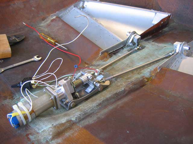
It looks bigger than it is. The motor is about four inches long, and the pushrods going to the cowl flaps are quarter-inch diameter, .016 wall stainless steel tubing. The washers lying nearby (below) are #10. Here is a closer look at the actuator:
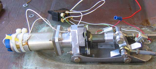
The whole thing rests on a sheet-aluminum shoe that bolts to the cowl top. (You're looking at it upside-down, of course; on the airplane, it hangs from the top surface of the cowling.) From left to right, there's the gearhead motor, an aluminum adapter/support, and a bearing block and jackscrew cannibalized from a Lear Siegler linear actuator. The jackscrew is fully retracted in the picture, and also hidden by the greenish dust cover. An aluminum rod end is pressed and pinned to the end of the jackscrew nut, and inserts in a clevis that projects from the top of a rocker. The rocker pivots around a bolt through the shoe and includes positive motion stops at plus and minus 30 degrees. The pushrods are bolted to the rocker halfway between the jackscrew connection and the pivot bolt, providing a mechanical advantage of 2:1. Two microswitches shut off the motor when the apparatus reaches its travel limits. The DPDT switch visible behind the motor is for testing purposes; the actual switch is a rocker located between the throttle and the trimwheel.
[June 10, 2006]
Nearly all the parts for the cowl flap mechanism are made. I had to recontour the inner skin of the cowl top, shorten the engine lifting lug and re-route the breather tube to accommodate the thing -- nothing is ever quite so simple as it seems when I first visualize it -- but all the parts fit now. I can turn the jackscrew easily with a screwdriver, so the starting and running friction, which I assume will anyway diminish with use, are not excessively high.
The trickiest component to make was a 7075-T6 aluminum bushing that connects the jackscrew to the electric motor. It is keyed to the jackscrew shaft and snugged up against the supporting ball bearing by a thin-walled nut that disappears from sight down inside the bushing. Everything is then locked with a roll pin. I've never cut a keyway before, and I don't have any real broaches or whatever tool is appropriate. I made a sort of stout chisel 3/32" wide by grinding down a 1/4" drill bit, and then scraped the keyway, which is 1/16" deep, using my drill press as an arbor press. Surprisingly enough, it worked. The only component still remaining to make is a bracket to support the two travel-limit microswitches. I will then install the assembly so that I can at least fly the airplane again, and put in the actuating switch, limit switches, monitoring LED, and wiring later. (The LED is to let me know when the motor is running; it goes out when the actuator reaches either end of its travel.)
[May 26, 2006]
Step by tiny step, the setup for actuating the cowl flaps with an electric motor is getting made. I found when I fitted the flaps to the cowling that the small misalignment at the trailing edge of the left flap could be easily eliminated, and they both fit pretty well now -- not that it even matters. Here they are in their fully-open (taxiing, parking with a hot engine) and fully-closed (low-power cruise or descent) positions, and as seen from underneath. The actuator motor will be secured to the top cowling, about a foot behind the flaps.
[May 6, 2006]
I finished the sheet-metal work on the second cowl flap yesterday. It did seem as though breaking the twisted torque box into smaller pieces of metal relieved most of the stress in it, but I won't be sure how good the fit to the cowling is until I've installed the flap hinges.
Back when I was planning to operate the cowl flaps manually, I was concerned about the direction and magnitude of the air loads they would experience, and I made up a little CFD model of the cowl (as a closed plenum with an inlet, a central obstruction representing the engine, and an outlet containing a turning vane). I didn't learn much from it, other than that CMARC can handle streamlines in strangely shaped spaces; but it produced an interesting image. Here it is. As usual, color represents pressure, with the warmer colors indicating lower pressure and higher velocity. It appears that there is a large area of low pressure on the aft portion of the turning vane, suggesting that its natural tendency will be to open rather than close.

[April 29, 2006]
As I hoped, progress on the second cowl flap has been faster than on the first, now that the kind and arrangement of all the pieces is established. I am making one small design change, however, because the first flap, although I assembled and riveted it in a rigid jig, once removed from the jig popped slightly out of shape. Its twisted shape is not one that comes naturally to sheet metal, and so, after you have forced the pieces into alignment and riveted them, when you remove the assembly from the jig it naturally seeks the position that minimizes stored stress. The distortion is slight -- about 1/16th of an inch at the trailing edge, which in theory was supposed to lie perfectly flush with the top of the cowling with the flap closed. Fortunately, the flaps would be closed only for descent, or possibly for low-power cruise in Arctic conditions, but never on the ground; and the trailing edge of the flap is not visible from the cockpit when it is in the closed position anyway. So, as people around here always say when rationalizing a blemish, "You'll never see it from Burbank."
I considered a couple of approaches to preventing this problem in the second cowl flap. One would be to forestall it by building a bit of excess twist into the jig, so that springback would bring the part to the desired shape. This would involve some guesswork, since the right flap, which I'm making now, is not of quite the same size or shape as the left. Another approach was to subdivide the inner skin of the torque box into three panels, each of which would incur a minimum of internal stress. I decided to go with the subdivision method.
In the meantime, I was thinking about how to wire the motor, which drives a jackscrew with a limit switch at each end of its travel. This is a very common kind of circuit, but since I always manage to come up with the most complicated way of doing things I asked a couple of friends to suggest how they thought it should be done. In the meantime I designed my own circuit. My two helpers submitted the same design, which requires one dpdt momentary-contact switch (or rocker) and two single-pole microswitches. My version was basically similar, but I managed to cram in a couple of dpdt relays as well. Industry is probably full of people like me; that's why there are so many stupid designs on the market.
[April 24, 2006]
Today I flew up to Paso Robles, about 140 nm northwest of here, on Javier Arango's invitation to fly with him in his Sopwith Strutter. The airplane's nickname refers not to a proud way of walking, but to the arrangement of struts between the fuselage and the upper wing; the rather ungainly full version is "one and a half strutter." It took a VOR approach to minimums to get into PRB, but the clouds broke by midmorning. Flying in the Strutter was fun; it's not exactly a responsive airplane, but it's an honest and very flyable one. It can barely break 100 mph in a dive, but it has a great rate of climb with its 160-hp rotary engine and 100-inch prop. Phil Makanna, who has a great book out about WWI airplanes, took this picture as we blew by. The lump in back is me.
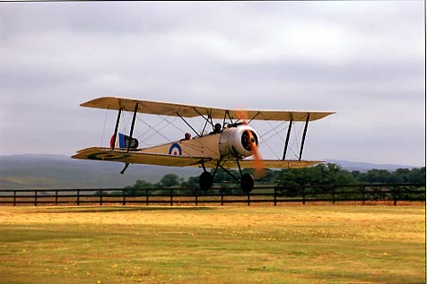
Melmoth's autopilot and GPS tracker worked fine, contrary to expectation, and its speed and fuel consumption were still consistent with an equivalent flat plate area of 2.3 square feet and a parasite drag coefficient of .022. I've begun leaning early in my climb -- may as well cool the engine with air, which is free, as with fuel, which is now $4 a gallon -- but this is a tactic that can be used only with airplanes that climb adequately at low power settings, and by pilots who don't mind taking it easy. Northbound I cruised at 10,500 ft and 163 ktas, burning 7.5 gph. Returning, I flew at 11,500 and 8 gph, trueing 169 knots. Those power settings are 51% and 55% of power, respectively.
I have one of the adjustable cowl flaps finished, and will begin the other tomorrow; I hope that now that I know some mistakes to avoid, it will go more quickly than the first, which took ten days to make.
[April 8, 2006]
I flew around for a while on the 6th. There was a scattered layer of small cumulus at around 5,000 feet and glassy air above. The mountains along the north edge of town are all snow-capped and their lower flanks are green from recent rains. Terrific visibility. I collected some speed-power data that seemed to confirm that F is now around 2.3 sq ft. One indication, besides correlations between the airplane and the performance prediction program, is that a line through several speed-power points has a shallower slope than it used to; I take this to imply a smaller parasite drag component.
The autopilot, which I thought I had repaired (broken wire), is still not working.
Bored with the new seat, I spent several days modifying the old cowl flaps so that they would rotate as intended without bumping into anything inside the cowling. I think I've got that part down now, and today I made templates for the edge ribs. I've decided to use the electric motor initially and to test how much engine power I would be able to use, and for how long, without overheating, if the cowl flaps were to fail in the closed position. That will give me a basis for deciding whether to use an electric or a manual actuation system.
One of the advantages of the moveable cowl flaps will be a super-open position that will drain hot air from the cowling much more effectively on the ground. Although placing the injection manifold in the air inlet nearly eliminated the fuel-heating problems that use to plague me, the injectors are still on the hot-air side of the engine and long idling or taxiing eventually brings about some roughness.
[March 23, 2006]
I have been working on a new seat and, at the same time, on making the cowl flaps adjustable. Today I went to a local surplus store, Apex, where I promptly found a little 24-volt gearhead motor of exactly the same type as I use for switching fuel tanks automatically. It would be ideal for operating the cowl flaps, using the same type of 6-pitch double-lead jackscrew as I used for the revised pitch trim. But I'm vacillating about whether it would be preferable to operate them electrically or manually. Electrically is a little more convenient both in construction and in use, but there is a possibility of the system failing with the cowl flaps closed. A manual system has fewer failure modes and is more likely to give warning of impending failure. A combination, similar to electric trim in being basically a manual system with an electric motor to drive it, would be rather complicated. One of these days I'll make up my mind. In the meantime I'm making a new pair of cowl flaps to replace the scuzzy temporary ones at whose picture you may scoff in the entry for September 23, 2005.
[March 11, 2006]
The past month has been devoted to rear seats, or rather to providing the necessary seat and seatbelt anchors for seats that will be installed at some future time. I intend to make a new pair of front seats, applying lessons learned from several years of flying with the present ones, and to put the present seats in the back, where they will face aft. Getting into the rear seats is far from easy, and will require that the backs of both the front and the rear seats be able to fold down flat. Once you get seated, however, it's perfectly comfortable back there, with full legroom, more than 48 inches of shoulder width, and a splendid view. Each rear seat is held in place with three pins and a single screw, and rests on two graphite rails that underpin the floor. The flap master cylinders and the oxygen system will both be located in the subfloor space below the rear seats.
The lessons learned from the first pair of seats were three. First, and this seems rather obvious now, instead of making the supporting surfaces for the pan and back match the desired seat angles and contours and then adding padding on top, I should have made the supports as thin and as close to the outside envelope of the seats as possible, and provided all the tilt and contour with the padding. The new seats will be able to have twice the cushion depth of the original ones.
Second, the seat pans should be longer than I made them (copying a VW Jetta seat); they will be 18 or 19 inches long rather than 16, and will extend to within a couple of inches of the crook of the knee.
Finally, in M2 the seats are mounted on a flat floor with very little space beneath them. With the present seats, whose pans are tilted, the gap between seat and floor tapers from maybe an inch deep at the front to zero at the rear. It makes a great trap for pencils, film cassette canisters full of earplugs, and so on. If there is a space under a seat, it should either be deep enough to allow storing things (like charts) and reaching in to retrieve them, or else so shallow (and perhaps equipped with a seal of weatherstripping around its perimeter) that it can't swallow up debris and valuables.
There's more to aeronautical engineering than meets the eye.
[February 13, 2006]
The drag of a blind cavity -- one with no leaks other than its opening in the airplane surface -- is difficult to predict. Hoerner gives a drag coefficient of 0.01 based on the area of the opening, assuming that the entire break in the skin lies parallel to the flow direction and does not present a hole facing into the free stream. The reason the value is so small is that air generally blows right past the opening, while friction with the passing air merely causes the small mass of air inside the cavity to rotate at a comparatively low velocity. If the two air masses remain generally separate, they exchange little energy. I suppose, however, that if the geometry of the cavity is such that passing air enters it in one place and leaves at another, or if passing air is drawn into the cavity and then separates at its aft edge when rejoining the free stream, the drag may be greater.
My nosewheel well opening is 40 inches long, and is 10 inches wide for most of its length; the area of the opening is about 375 sq. in., or 2.6 sq. ft. At my usual cruising speed (around 135-140 kias) a change in indicated airspeed of one knot corresponds to about .1 gph in fuel flow and about .1 sq ft. in equivalent flat plate area. The apparent speed gain of 2-3 knots from adding the doors implies a drag coefficient ten times larger than Hoerner's. I conclude that either the higher speed is the result of wishful thinking on my part, or else there must have been some exchange of energy between the air inside the well and the air passing by. If the latter is the case, I attribute it to the location of the well very close to the front of the airplane and immediately behind the propeller, where the boundary layer is still quite thin, and perhaps also to the complicated collection of stuff inside the well with the gear retracted, which would have disturbed the circulation of air within the well.
[February 7, 2006]
I did a couple of speed checks with the new nosewheel well doors and was pleasantly astonished to find an increase of several knots. This remains to be verified over a number of flights, but my equivalent flat plate area seems to have dropped from 2.5 to 2.25 square feet.
Here is the door mechanism:
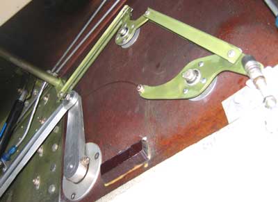
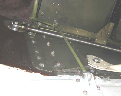
The first picture shows the right side of the well; forward is to the left. The gear is down; the green part of the well is the aluminum engine bearer cum nosewheel compartment; the reddish-brown area is part of the composite fuselage structure. On retraction, the large aluminum arm swings 90 degrees aft (that is, to the right), coming to rest against the stop block. On the way down it contacts a roller (hidden from view) on the end of the S-shaped bellcrank and pushes it downward. The other end of that bellcrank raises the right door by means of the short link just visible, and very overexposed, at lower right. At the same time, the motion of the bellcrank is conveyed through an idler to a torque tube running across the top of the well -- the green thing angling toward the upper left. In the other picture, which shows the left side of the well -- the front is now to the right -- the arm on the torque tube is connected by the slender green tube to the left door. The large stainless steel tube running from left to right is a nosewheel steering actuator.
As far as the payoff is concerned, my method of assessing performance changes is to correlate observed speeds and fuel flows with my performance calculation program, which does a fairly good job of keeping track of all the variables. I collect speed/fuel flow data at random, set up the program parameters to match the altitude and weight, and vary flat plate area until the observed performance matches the calculated. The program takes care of the induced-drag component, I hope accurately. In any case, here are some observed performance points, reduced to density altitude, fuel flow and indicated airspeed, with true airspeed added in parentheses. The final value is the calculated equivalent flat plate area. EGT is always about 60 degrees lean of peak (by TIT). Incidentally, to convert the equivalent flat plate area to a parasite drag coefficient (CDo), divide by the wing area, 106 square feet.
8/30/05: 14,000 ft, 8.6-8.7 gph, 138 kias (171 ktas); 2.6
9/2/05: 14,500 ft, 8.6 gph, 139 kias (173 ktas); 2.5
1/2/06: 13,500 ft, 8.2 gph, 139 kias (170 ktas); 2.4
1/14/06: 12,200 ft, 8.7-8.8 gph, 143 kias (172 ktas); 2.5
2/8/06: 12,000 ft, 7.7 gph, 140 kias (167 ktas); 2.25
2/8/06: 10,000 ft; 7.4 gph; 137 kias (160 ktas); 2.25
The change in equivalent flat plate area, evidently due to the nosewheel doors, is clear. Based on the present value, the maximum cruising speed at 150 hp, assuming a critical altitude of 17,000 feet, would be around 200 knots using 10.4 gph.
[February 4, 2006]
So it's true: everything takes two months. I finished the nosewheel doors today. My estimate of two or three weeks to do the left door -- I've have the right one working for a month -- was as usual optimistic, though not so much as it seems, since I made two three-day trips in the past month. I have not yet gathered any speed data yet; I'll do that next week.
[January 4, 2006]
As was the case last year, the year's-end holidays entailed so much cooking and cleaning up -- we entertain a lot -- that I scarcely got out to the airport at all. Today I finally finished up the right nosewheel door and did a short test flight. Everything worked as hoped. Now I have to mount the left door and install the linkage, consisting of two bellcranks, three pushrods and a torque tube, that connects the left door to the right. This should not be very complicated, and I hope to get it done in two or three weeks rather than the month the right door took. The flap actuation system has been pretty much on hold for this, as have the cowl flaps and the back seats.
[December 18, 2005]
I've been working for the past couple of weeks on the nosewheel doors. In the course of testing the actuation system, I found that in three years of operation the connection between the main and the nose actuators -- all three struts' retractors are mechanically interlinked -- had developed some play. The bellcrank that was supposed to be holding the nose strut up and locked by going overcenter was not, in fact, going all the way overcenter at all. Trapped hydraulic fluid holds the nose strut up anyway, but the full overcenter motion of that bellcrank was needed for closing the doors. After some floundering around and several false starts I realized that the best way to correct the problem was to adjust the lengths of some push-pull rods in the wing centersection. When I did this I was rewarded not only by proper actuation of the right-side door -- I have still to build the linkage for the left one -- but also, unexpectedly, by the right main gear doors' closing more snugly than they had ever done before.
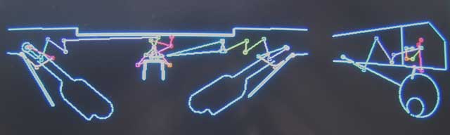 The
system by which
the three gears are linked to one another is pretty simple, but the
system by which the inboard main gear doors open to let the wheels go
by and then close again is a bit trickier. There are no cams or lost
motion devices; everything is bellcranks and links. I spent a lot of
time, years ago, perfecting the kinematics, and even more time writing
a computer program that displayed the motions of all the parts and
analyzed the stresses in them. Unfortunately, the program, originally
written for DOS, now seems to display all of its text in Armenian --
the result, no doubt, of some kind of dirty tricks by Microsoft. But
the animated gear action can still be seen. The actuation system for
the nosewheel doors, I confess, violates the no-lost-motion rule; using
only bellcranks and links, it's very difficult to get the doors fully
open quickly enough to clear the tire as it begins to drop out of the
well.
The
system by which
the three gears are linked to one another is pretty simple, but the
system by which the inboard main gear doors open to let the wheels go
by and then close again is a bit trickier. There are no cams or lost
motion devices; everything is bellcranks and links. I spent a lot of
time, years ago, perfecting the kinematics, and even more time writing
a computer program that displayed the motions of all the parts and
analyzed the stresses in them. Unfortunately, the program, originally
written for DOS, now seems to display all of its text in Armenian --
the result, no doubt, of some kind of dirty tricks by Microsoft. But
the animated gear action can still be seen. The actuation system for
the nosewheel doors, I confess, violates the no-lost-motion rule; using
only bellcranks and links, it's very difficult to get the doors fully
open quickly enough to clear the tire as it begins to drop out of the
well.
Revisiting the whole system I now feel that, given the short moment arms available for some bellcranks and the relatively high forces involved, I was too ready to use small hardware and bearings. Their strength is sufficient, but I now think that sometimes it's better to use more massive components with lower surface loadings; they wear more slowly, remain in adjustment longer, and are more resistant to damage and overload. Perhaps this is why, though I got away with a single 3/8-inch bolt in a spherical bearing at each end of the main gear trunnions in Melmoth 1, Piper selected a thick-walled steel cup an inch or more in diameter for the same purpose in the Arrow.
At the same time, I have also been machining components for the flap master cylinders and preparing to install adjustable cowl flaps. After worrying for a long time about how best to actuate the cowl flaps electrically, I decided that they could equally well be manual -- a great simplification, and relief as well.
[November 30, 2005]
Yesterday I flew up to Paso Robles, where Javier Arango has a beautiful collection of very exact WW1 aircraft replicas. Most are flying with the original engines, and because there is a shortage of 110-hp Le Rhone rotaries in the world Javier is having a set of ten made to order by a first-rate machinist. The crankcases are machined from a 605-lb steel cylinder, and weigh 37 pounds when finished. Lots of chips. The French and British turned out something like 30,000 of these things between 1917 and 1919. Anyway, it was a beautiful day for flying, but a high and a low side by side were squirting the wind southwestward at a pretty good rate. I flew up at 10,500 feet to stay above the turbulence, and my ground speed was 115 knots. The return trip a few hours later made up for it, though; at 13,500, using 8.3 gph, the groundspeed was 220 to 230 knots, and I briefly saw 254 when I started to descend.
[November 21, 2005]
I flew to Santa Maria today to visit Paul Lipps, an exponent, like me, of the "piece of shit" school of craftsmanship. Nevertheless, he cares about neatness where it counts. When I was getting ready to leave he cast a disapproving eye on my wings, which have not been washed since before Oshkosh 2004. He wetted a towel and handed me a dry one, instructing me to follow along behind him. He cleaned off a year's worth of dead bugs and I wiped away the water drops and dusted off the top of the wing. It happened that I had collected some performance points on the flight up, and I collected more on the flight down. It appeared that about a tenth of a square foot had been shaved off my equivalent flat plate area. This is not so surprising as it sounds, since the difference between "standard roughness" and full laminar flow is about 60 "counts," that is, .006 square foot of equivalent flat plate per square foot of exposed wing area. My exposed wing area -- this is planform area, not wetted area -- is about 85 square feet, and so the difference in drag between the absolutely worst surface condition and the absolutely best would be half a square foot of equivalent flat plate. Of course my wing was neither the worst nor the best, but it's possible that there was enough crud on it to eliminate a good deal of laminar flow.
Paul reported losing several knots when the nosewheel door actuator on his Lancair 235 (which cruises 173 knots on 5.6 gph, running rich) broke and the door failed to close; that gave me hope that I may see some benefit from closing up that vast trench on my airplane.
It was a magnificent day for flying, especially in the late afternoon, with air of an aquarium-like limpidity, infinite visibility, and some ragged clouds to filter the light of a lowering sun. Although the trip takes only 45 minutes, I climbed to 11,500 feet and was glad I had. Los Angeles is not a city noted for its beauty, but on an afternoon like this "Earth has not anything to show more fair."
[November 12, 2005]
The trim system has been working well. I will not know whether it has sufficient authority for the full CG range, however, until I have the flaps working. I did replace the old pushrod with a straight half-inch-diameter hollow pushrod, which unclutters the area a bit more. The trim system changes removed about 10 ounces. That's how it always is: remove ounces from one tail, add pounds in another.
I modified the mount for the GPS coupler to angle it toward the pilot; it was hard to see the LEDs. I may eventually move it to the top of the panel directly in front of me, but for the time being it is to the right of the panel centerline. I don't like the way the mounting bracket protrudes from the panel; it seems to violate basic crash safety principles.
I finally began working on the master cylinders for the flap actuation system. I had to ask around to find a welder; they come and go, and I haven't used one in a long time. Flyte-Weld, near Burbank Airport, did a beautiful job joining the cylinders to their bases, and didn't charge much. As usual, I am designing the things as I go along, and making an extra one in case I screw up.
I am also finally fitting the nosewheel doors. I laminated the doors themselves probably a decade or so ago, attached hinges to them nearly a year ago, and am now putting the mating hinges in place on the edges of the wheel well. The operating mechanism for the right door is quite straightforward; the left one is a bit more complex, since the motivation comes from the right side of the well and has to find its way over the top of the retracted gear strut to reach the left side. I'm very curious to see whether any speed gain comes from closing up the well. You'd think a 10-inch-wide, 30-inch-long sharp-edged cavity in an airplane's surface would produce some drag, but Hoerner gives a CD of .01 referred to the area of the hole. That would be 3 square inches of equivalent flat plate, an improvement of 0.82% -- not enough to measure.
[October 19, 2005]
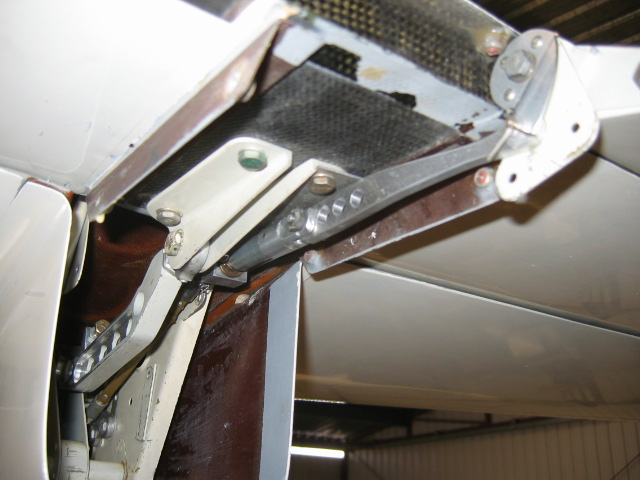 I
finished the new pitch trim mechanism yesterday and test flew it today.
It works. A chain rotates a sprocket (hidden from view in the picture)
that is connected, via a universal joint, to a telescoping shaft of two
nested thin-walled square brass tubes. The shaft has to telescope
because its length changes by a couple of inches as the elevator moves
up and down. It connects, through a second universal joint, to a
6-pitch double-lead jackscrew that is mounted on the bottom of the
elevator, supported by the squarish aluminum bearing block. The fore
and aft movement of the jackscrew nut positions the trim tab through a
short link (upper center, with the three lightening holes in it). I
made the mistake of greasing the brass tubes, which actually increases
their resistance in cold environments; but it will be easy to clean
them.
I
finished the new pitch trim mechanism yesterday and test flew it today.
It works. A chain rotates a sprocket (hidden from view in the picture)
that is connected, via a universal joint, to a telescoping shaft of two
nested thin-walled square brass tubes. The shaft has to telescope
because its length changes by a couple of inches as the elevator moves
up and down. It connects, through a second universal joint, to a
6-pitch double-lead jackscrew that is mounted on the bottom of the
elevator, supported by the squarish aluminum bearing block. The fore
and aft movement of the jackscrew nut positions the trim tab through a
short link (upper center, with the three lightening holes in it). I
made the mistake of greasing the brass tubes, which actually increases
their resistance in cold environments; but it will be easy to clean
them.
The old system, pictures of which can be found in the "Pictures" neighborhood of this website, was much more complex because the trim tabs acted as servo tabs as well, intended to reduce pitch forces. It turned out, however, that pitch forces didn't need to be reduced, and there was insufficient trim authority to maintain cruising speed with a heavy load in the back seats or, for that matter, to trim to 1.3 Vs for landing approach with a forward CG. Whereas the old system provided only five degrees of tab travel for trim, this one provides 27. Since it uses only one of the two tabs, however, and lacks the moment-reducing servo effect, it is not five times more effective than the old system but perhaps only two times. It's also about half a pound lighter.
[October 1, 2005]
I dug up some old pictures. Construction of the airplane began in a hangar at Whiteman Airport, but soon moved to my house in Echo Park. Here is the fuselage in the garage, where it remained for about ten years:
 The
garage was ten feet wide, the airplane eight, and the workbench two.
The place eventually became so crowded that I had to get down on my
hands and knees to move from one part of the airplane to another.
The
garage was ten feet wide, the airplane eight, and the workbench two.
The place eventually became so crowded that I had to get down on my
hands and knees to move from one part of the airplane to another.
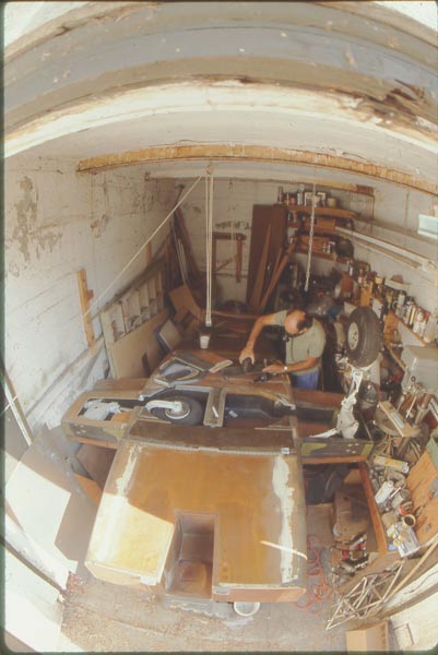
Mitzi Trumbo took this picture with a fisheye lens from atop a ladder just outside the garage door. The length of the fuselage and of each wing panel (at this point the wings were stored in the basement of the house) was determined by the length of the garage, which had been built in the era of the Model A Ford. Eventually further progress became impossible, and I moved back to a hangar at the airport.
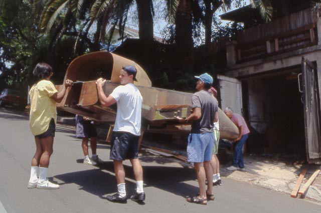
A bunch of friends helped carry the plane out of the garage. This was early in the 1990s. The dramatis personae are, left to right, Tom Shima,Carl Byker (legs only), Matt Damon (then available for odd jobs), myself, Aaron Stockard (legs again), and Walter Field.
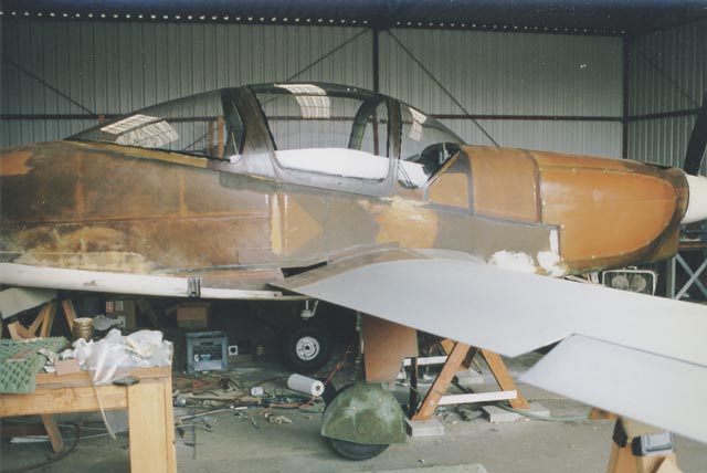
In the hangar, I began to progress more rapidly, and by the late '90s most of the parts were in close proximity to one another. The canopy had just been tacked into place when I took this picture. The piecemeal assembly of components cured at different times is evident, as is a somewhat casual approach to the application of leftover surface filler.
[September 23, 2005]
This morning I gathered some data about cowling pressures with the new cowl flaps, which are currently locked in the open position. I used two water manometers, one comparing the high pressure plenum (below the engine, fed by the cooling air intake) to the low pressure plenum (above the engine and vented to the outer world), and the other comparing the high pressure plenum to ambient (static) pressure. The ratio of the difference between the two plenums to the free stream dynamic pressure is called the engine pressure difference or pressure drop; the ratio of the high pressure plenum pressure to the dynamic pressure is called the pressure recovery. I found the pressure recovery to vary from .68 at 90 kias to .54 at 140. On the other hand, the engine pressure difference, which is boosted by the extraction effect of the cowl flaps, went from .86 at 90 to .84 at 140. The pressure drop seems fairly good, but the pressure recovery is mediocre, possibly because of poor diffusion of the inlet air.
Here is how they look -- namely, like bits of scrap metal found lying about. Actually, the left one is what was there before, but with different side flanges and in a different position; the right one was made from scratch. Despite protruding, they do not seem to affect performance. The idea is to make them rotate in such a way that the rear edges become flush with the cowling, closing off the rear outlet, in cruise, while the front opening narrows somewhat. The gray area behind the left outlet is just primer, and has no particular significance.
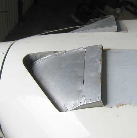
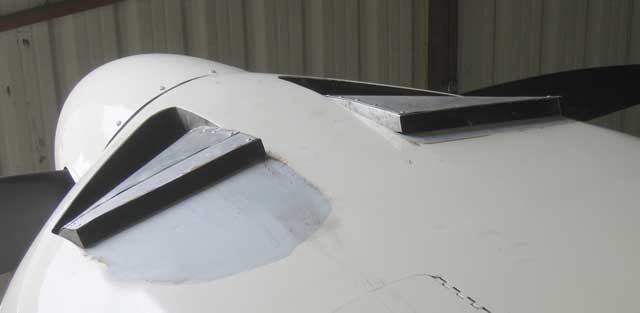
[September 16, 2005]
In the course of the random walk that passes for the development and refinement of Melmoth 2, I was suddenly seized, early this week, by an impulse to fiddle with the turning vanes (that is, cowl flaps) in the cowling air outlets. I cobbled up a new pair, which are not flush like the old ones, but rise up somewhat above the surface of the cowling on the principle that the plume of air emerging from the cowling does the same. They look like something from a Wilga, but they increase the outlet area and improve the cooling considerably, dropping CHTs by a good 40 deg F. Actually, I shouldn't say "good," because the CHTs are below the manufacturer's recommended values now, but that's all right; eventually the cowl flaps will be adjustable, and it will be possible to raise the temperatures to the desired level (380 F, says Continental).
The left front and right rear cylinders continue to be hotter than the others. I suppose they must be hotter for different reasons, since they have nothing in common that I can tell. My current theory, which I have held on and off for some time, is that the left front cylinder is being heated by the proximity of its own exhaust pipe, and the left rear by improper baffling. Time will tell.
I swapped the bad tenths digit on one VOR with the otiose hundreds digit. Why do they even have hundreds digits, since the number is always one? For spares, I guess. The same goes for COMs. The GPS tracker didn't work on the first test flight, so I read the instructions and learned that I had to enable downloading of the data stream to the tracker. Instructions are good.
[September 9, 2005]
On the cusp of September I made the 1,250 nm round trip to Santa Fe again, this time with unusually friendly winds; it took 7.1 hours and used 63 gallons of fuel. I thought I had taken off with 85 gallons and didn't refuel in Santa Fe, but was then surprised to see the fuel relatively low when I got back. Deciding it was high time that I at least calibrated the zero points on the fuel gauges, I drained the tanks and found that I had 11 gallons left, not 22 as I had imagined. Calibrating the gauges was difficult because the senders, which are the primitive resistance type with a float on an arm, came from the first Melmoth and are therefore at least 30 years old. They have some dead spots and produce some spurious zeros. I think I got a decent calibration, however, and at least I now have a proper initialization for the Alcor digital totalizer.
A couple of things went wrong on the way. Something slipped in the airbrake control, and the brake would blow closed after a few seconds. And a digit burned out in one of the Collins Microline VOR heads. The airbrake problem was easily fixed, but the digit seemed alarming -- they're $135 each -- until the guy in the local radio shop pointed out to me that the first digit in VOR frequencies is always a one, and so you can swap the first digit with the faulty one (which is the tenths digit) without losing any information.
There was a downpour while I was in Santa Fe, and when I exercised the controls before taking off I noticed that the stabilizer felt heavy; with full back stick the intersection fairing dumped a bunch of rainwater down the fin cove. I had never provided the fairing with a proper drain hole. I remedied that today, but it is not a perfect situation; it's still conceivable that water could collect inside the fairing and freeze.
Today I wired up the Porcine GPS tracker, but I won't have a chance to test it until Monday.
[August 13, 2005]
Having returned from vacation, I flew for 40 minutes or so yesterday to exercise the airplane and to further investigate the effect, if any, of the flap track fairings. At 10,500 feet, where the density altitude was a bit over 13,000, at 2,400/27 with the mixture about 60 deg. F. lean of peak, I got 166 ktas on 8.1 gph. Feeding this back through the performance prediction program, I find the same 2.55 sq. ft. equivalent flat plate area as before. I should have done a complete speed-power curve before and after installing the fairings, because I'm now stuck with only a few isolated performance points. A while ago (pre-fairings) I recorded 166 ktas on 8.3 gph, but slight differences in density altitude and mixture setting can easily account for a couple of tenths of a gallon per hour. At this speed, however, one-tenth of a gallon per hour is roughly equal to a knot. I'm sure that the fairings must have produced some benefit, but it's hard to measure a knot when your margin of error is two knots.
[July 21, 2005]
One of the irritations of the generally wonderful Internet is the amount of outdated information on it. I'm not innocent. The website of the software company in which I'm a partner, AeroLogic, is extremely cobwebby. Just keeping a commercial website up to date is a full time job. My ranting about this is due to my having spent an unreasonable amount of time trying to locate a small universal joint and sprocket for my revised pitch trim system. You can find the online parts catalogs easily enough, but the lists of suppliers are out of date, their phone numbers are disconnected, and so on. I'm having similar trouble with Lowrance, the GPS maker. I want to get a coupler that will allow my AirMap 300, donated by a kind friend, to talk to my autopilot. A fellow named Jim Ham sells these inexpensive ($250) couplers -- his website, I hope up to date, is www.porcine.com (get it? ham:porcine) -- but Lowrance no longer provides the required cable, even though the particular unit went off the market just four years ago, which seems pretty recently to me, but maybe not to a 21st-century electronics company. I will make a cable, but only after a tiresome wild goose chase in which Lowrance directed me to suppliers that had ceased operations and web pages that are no longer accurate but that continue to litter the web like unburied corpses. Well, no matter; sooner or later things get done, and the delays give bad ideas time to settle to the bottom. I'm off to Cape Cod for two weeks, the plane remains in the hangar, and nothing new will happen until well into August.
[July 5, 2005]
Based on a short flight today, the speed gain from the flap track fairings was on the order of one knot. Well, maybe less. Maybe half a knot. Maybe nothing. They look nice, though.
[July 3, 2005]
It took five days, and an uncommon (for me) number of hours per day, to remove the entire nose gear assembly, repair the failed bearing retainer, fit the new steering tiller, and inspect and refurbish stuff as needed. Actually, I made the new top for the tiller twice. The first attempt turned out to have all sorts of interferences that were perfectly obvious once I had made the part and installed it; apparently not so obvious, at least to me, when I was merely visualizing it. I should have made a test item out of wood first; it machines more quickly than aluminum.
I replaced O-rings in the shimmy damper and nose strut actuating cylinder, cleaned everything up, and felt pretty good when it was all back together. Even though I don't fly the plane all the time, it's frustrating to have it unflyable. I still need to jack it and cycle the gear, and then fly, perhaps on Tuesday.
The sliding-out of the bearing was due to two engineering errors. One was the lack of a retaining lip on the outboard side of the bearing holder; the other was the lack of a large-area washer on the inboard side. In general, it's good engineering practice to incorporate a large-area washer wherever a pressed-in bearing can slide out of a socket. I had omitted one here because I thought that the stiffness of the U-shaped retraction arm, which is trapped between the sides of the wheel well, would prevent the right side, through which all the landing loads go, from moving inward. Wrong.
[June 25, 2005]
During a preflight inspection on Friday I discovered that the spherical bearing that carries the principal drag load from the nose gear into the engine mount structure had slipped completely out of its socket. Here is the area of the failure; it's just aft of picture in the previous entry, below. (In this picture, taken some time ago, everything is still intact.)
The bearing in question was pressed and staked into the round aluminum plate that is secured with six rivets to the steel weldment. The unpainted aluminum arm (right) and link connect the nose gear retraction arm (white) to that of the mains. A small hydraulic cylinder (left) and a gas spring (black, with blue label) help to overcome the aerodynamic drag of the gear as it goes down. Interestingly, the bearing holder failed in tension, apparently as the nose dropped down onto the runway during rollout on the previous landing. Although I had let the nose down a little harder than usual, I was not aware of anything having broken. Events like this, though rare, demonstrate the value of a thorough preflight inspection.
The only damaged part is the round aluminum bearing holder, which will be easy to replace. I will provide the new one with a more substantial lip to retain the bearing. I pulled the entire nose strut out of the airplane on Friday afternoon. The timing of the failure was fortuitous, since I had been planning to modify the steering mechanism anyway (see previous entry below). This will give me a chance to inspect the whole assembly.
[June 22, 2005]
I returned yesterday from a week in Korea, where I was investigating the effects of kimchi -- fermented spiced cabbage. I thought it was awful stuff, but it seems beneficial to the body, at least in the short run: practically all Koreans looked extremely trim and fit, whereas almost all the westerners I saw, including me -- those hotel triptych mirrors will stand aye accursed in my calendar -- looked like undercooked puff pastries.
As far as I could tell there are no private planes in Korea, or, if there are, they don't fly very often.
Before leaving I changed the oil in the airplane. I continue to marvel that I could have made this most recurrent of minor maintenance tasks so difficult. I always end up sitting in a pool of oil and bleeding. I've decided that before I do anything else I'll modify the steering tiller, which is to blame. The present arrangement looks like this:
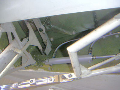
The T-shaped thing running up the backside of the nose strut is the tiller. Partly visible behind its left arm is the cover for the oil drain plug, which is nearly impossible to get at because of the crossbar on the T. I've decided to put off whatever my next task was going to be (trim? ailerons? cowl flaps?) and replace that T with a U-shaped yoke. (If you're curious, there are some views of the lower end of this steering shaft at the bottom of the "Pictures" page.) The whole thing disengages from the rudder pedals when the gear retracts. When the gear is down, the ends of the tiller are in contact with the tabs at the ends of the rectangular aluminum bar. The steering pushrod, which is connected to this pivoting bar, runs along the left side of the wheel well, hidden in this picture, and links directly to the rudder pedals without any intervening cables or springs.
[June 4, 2005]
Finally both of the flap track fairings are installed, though the right one still needs to be sanded, primed and painted. These minor-seeming projects end up taking forever -- I started working on the fairings in the middle of March -- but it's partly because of interruptions for work or travel, partly because of my only putting in an hour or two a day and only on weekdays, and partly because of the nature of composite work, which, at least on the scale on which I practice it, seems to break down naturally into a series of small projects each of which absorbs one day's effort.
Now I must decide what to do next. The leading candidates are nosewheel doors, oxygen system, aileron hinges, back seats, trim revision, cowl flaps, and landing flap actuators. No doubt I could come up with a dozen others if I jogged my memory with the long list called "M2 to do.doc." I feel the strongest tug toward the ailerons, because I think they would produce the most gratifying result with the least effort. Of course I always systematically underestimate the effort that any project will require, but never mind: that applies to all projects equally. The easiest job would be the trim revision, but I keep putting it off because I can't locate a certain aluminum pillow-block that I've had for about 30 years, and that would be just perfect for part of this job. I don't really need to use it, but it's so right that it would be a shame not to. So I keep searching through boxes of disjecta membra from the first Melmoth, in what would be a metaphor if my life were a novel. If I find it, the agenda may suddenly change.
Perhaps, on the other hand, I should stop working on the plane for a week or two and devote some time to giving rides to people to whom I've promised them; the list keeps getting longer.
[May 18, 2005]
Back from Baja.
Mirabile dictu, I think I detected just the faintest hint of out-of-center ball, apparently attributable to the wing with the flap track fairing having slightly less drag than the other. Unfortunately I do not have a well-established speed/power/EGT/fuel flow grid, based on inflight measurements, that would allow me to make delicate comparisons of drag. My method of estimating drag is to vary the drag parameter in my computer simulation until the predicted performance matches the actual. That was the source of my estimate of 2.55 square feet of equivalent flat plate area. Uncertainty about specific fuel consumption and propeller efficiency, however, could produce errors of several percent.
I have not recalibrated my computer/airplane comparison since installing GAMI injectors, which would be expected to bring about an improvement in specific fuel consumption. This will complicate interpreting the speed/power data that I will take after both flap track fairings are in place. On the other hand, one does develop a sense of the expected IAS for a given cruising conditions, and any change for the better or worse is noticeable; but it's necessary to guard against what I think of as the Windex tune up phenomenon -- the fact that a car seems to run better after its windshield has been cleaned.
[May 12, 2005]
I finally got one of the two flap track fairings installed. (See March 17 below for the CFD version of the same thing.)
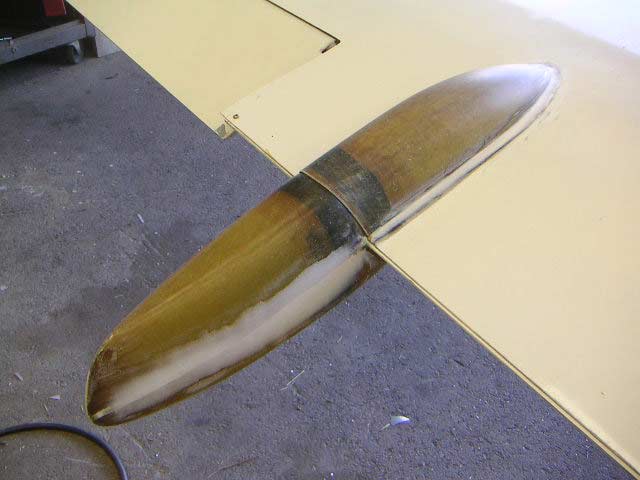
I'm leaving tomorrow for a few days in Baja California, and spent the last couple of working hours today attaching big numbers (required for ADIZ crossings) to the sides of the airplane with shelf paper. I should have been painting the fairing. Maybe I'll slap a quick coat on it before I leave tomorrow. But my impatience to tuft the fairing may surpass even my impatience to see it white. I'm also curious to see whether flying with only one fairing produces even the slightest right yawing tendency.
[April 25, 2005]
A trip to Santa Fe in continuous light to moderate turbulence convinced me to up the priority of reducing the stick forces in roll. I downloaded from the Internet (may peace be upon it) a NACA wartime report on aileron balance nose shapes. Unfortunately it mainly tended to confirm my sense that this is a topic upon which nothing definitive can be said. It does appear, however, that I will be able to move the aileron hinges aft, recontour their noses, and considerably reduce the weight of the static balances, all without venturing out of the zone of the tried and true, where I prefer to linger. I also discussed last week with Russ Hardwick various ideas for converting the present elevator trim system, in which both tabs double as servo tabs to lighten stick forces, to one in which one tab will be a servo and the other a pure trim tab. I feel now as though we arrived at a satisfactory solution to that problem, and so I may raise its priority as well.
The GAMI injectors had the expected effect of making all cylinders arrive at peak EGT at more or less the same time, so that it is possible to lean to a lower fuel flow, but turbulence made it impossible to collect a good set of data points on fuel flow, speed, and EGT.
[April 15, 2005]
I've been away to Boston and Corsica for a couple of weeks. Before leaving I installed a set of GAMI injectors, which differ slightly in bore diameter in order to better equalize the mixture ratios among the cylinders. I have not yet collected EGT data in flight to compare them with the factory injectors. Before leaving on the trip I was working on the tooling for the flap track fairings; I hope to have the parts made in a week or two, other obligations permitting.
[March 17, 2005]
Here's what a basic CFD model of the flap track fairings looks like:
My best guess from the analysis is that each fairing produces about four ounces of drag at normal cruise. There will be four tracks, so a pound of drag. How this compares with the bare tracks cannot be known, but the change will in any case probably be too small to measure with an airspeed indicator. Cruising drag for the complete airplane is around 200 pounds.
[March 12, 2005]
I have always had several books going at a time, and I always have several tasks going on the airplane. I work on one until it becomes boring or I encounter some difficulty or expense to which I feel unequal, and then I put it aside and take up something else. Currently I have the nosewheel doors, the oxygen system, the flaps, and the back seats in various stages of suspended progress, and to divert myself from them I have begun what I hope will prove to be a quick, simple and satisfying project, namely the outboard flap track fairings.
They seem as if they should not take long. On the other hand, they will probably not accomplish much, except perhaps aesthetically. The problem with some fairings, these included, is that while they are more streamlined than the structures that they cover, they are also much larger -- witness the huge "canoes" housing flap tracks on Boeing airliners -- and so they end up removing only a fraction of the drag that you wish you could eliminate completely. In this case, the flap tracks are oriented at right angles to the rear spars, which sweep somewhat forward; the fairings, on the other hand, must align with the local flow. As a result, the fairings have to be considerably wider than they would be if their axes coincided with those of the flap tracks. Furthermore, because of the oblique alignment of the tracks the fairings need to expand to a certain width fairly near their leading edges, and retain it until fairly close to their trailing edges. This situation raises what could be called the Constellation vs DC-4 question: is it better to have a body that has a continuously curved profile, or one that is narrower, but has a parallel-sided portion in the middle?
It is a great luxury to be able to worry about things like this, rather than whether or not I will be blown to bits next time I leave my house.
[March 4, 2005]
Fuel being as expensive as it is, I've been trying to use as little of it as possible, and so cruising at around 50-60% of power. I have been seeing good agreement with my performance program's calculated fuel burns and speeds if I assume an equivalent flat plate area of 2.55 square feet. The other day I recorded 166 KTAS at 7.7 gph at 12,500 feet, which was a little better than expected but within the range of uncertainty due to mixture, prop efficiency, etc. I have not done any high altitude speed points, but if the trends hold the 75% power cruising speed at FL180 should be around 195 kts. This is a little disappointing -- I was hoping for 300 -- but there is still some cleaning up to be done.
[February 25, 2005]
I got a ride in this today. Pretty slick. Details will be in the October issue of Smithsonian Air & Space.
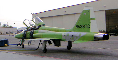
[February 22, 2005]
It's been raining regularly, and often very heavily, for almost a week. I've been working, rather desultorily I must admit, on the rails that will support the rear seats, on the oxygen system, and on the anchors for the inboard flap actuators.
The only aspect of this that is of the slightest interest is the oxygen system. I learned that the 76-cu. ft. cylinder that I have saved for the past 23 years, and for which a fitted cradle is built into the rear seat footrest, went out of date three years ago and is now, as somebody at one of the local oxygen equipment businesses said, a very large paperweight. It seems that it would be difficult to replace the exact bottle, which I believe may have been original equipment on some Cessna back in the 1970s, but smaller and lighter aluminum bottles are comparatively inexpensive and readily available. From various websites I learned that with proper breathing and regulating gadgetry oxygen consumption at reasonable altitudes (meaning just below 18,000 feet) can be pulled down to 0.4 liters or less per person per minute, which would mean that a 24-cu. ft. bottle would last two people more than 12 hours. That seems acceptable. My principal concern in assembling this system is to keep it cheap. A liter is about 61 cubic inches, by the way, and so there are about 28 of them in a cubic foot.
I have also been thinking about putting some sort of microswitches at the landing gear overcenter knuckles in order to avoid ambiguity (see below) about whether or not the gear is really down and locked. I wonder whether a thin piece of stainless steel, insulated from the surrounding metal and getting clamped in the knuckle when it goes overcenter, would not be a good deal simpler than actual microswitches. It's worth a try.
I
had a close call that may be worth describing.
About ten days ago I happened to look under the airplane and I noticed
that the inboard main gear doors were hanging slightly open. M2 is not
a P-51, and this should not be; if the gear is down, the doors, which
are mechanically linked to the rest of the retraction system, should be
closed. My eyes went to the overcenter locks on the sway braces (the
diagonal links that hold the gear legs down), and sure enough, both of
them were unlocked.
I remembered that two days earlier, returning from a flight, I had
slightly overshot the detent when returning the gear handle to the
center position after lowering the gear, and the pump had run
momentarily. Just a blip. The "down" indicator on the torque tube
hadn't moved, as far as I could tell, so I didn't give a countervailing
downward blip. This was pretty stupid.
The interesting thing is that I landed, taxied back and parked with
both sway braces unlocked. But it turns out that since the valve is
closed-center, the whole mechanism was held in place by the trapped
hydraulic fluid, which saved my (belly) skin, not to mention propeller.
So the lessons learned were:
1. The down position indicator is not a perfect gauge of the overcenter
position of the sway braces.
2. I need some microswitches and warning lights for positive indication
of overcenter.
3. Because of the closed-center valves, the gear is more or less safe
even when it is not fully locked.
4. Any pump sound, however slight, in the up direction is reason for an
additional shot of down pump.
Speaking of warning lights, since I installed a big red light to
indicate that the air brake is open, I have never forgotten to retract
it after landing.
[January 8, 2005]
The holidays, together with an extraordinary amount of rain, have been fatal to progress. I've only been out to the airport a few times, and only flown three times -- a round trip to Santa Fe before Christmas and a 20-minute hop to heat the oil a couple of days ago -- in the past month. I have, however, spent a lot of time on the design of the flap master cylinder array, using little models cut out of file folders and sheets of letter paper taped together to supplement their area as needed. This is what it looked like a few days ago:
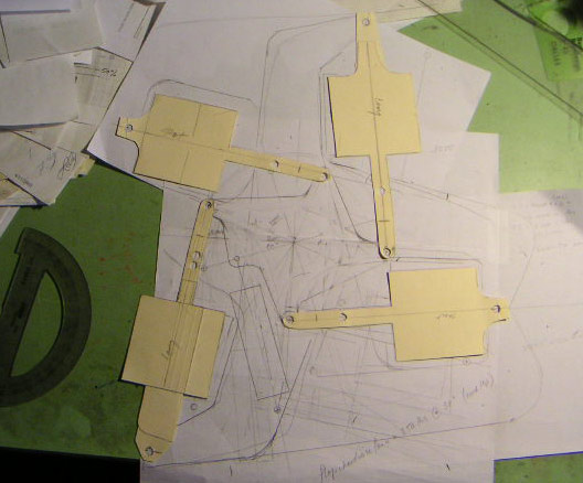
The geometry is fairly complex, and the whole thing needs to be strong enough to defend itself against the hydraulic forces in the cylinders. The tandem cylinders I first imagined have been replaced by four identical cylinders; the starwheel provides the differential travel for the inboard and outboard slave cylinders.
[December 4, 2004]
The eventual resolution of the outboard actuator problem involved moving the pivots to a point halfway between their original and their one-diameter-lower positions. As of Friday, both outboard actuators were properly positioned to extend and retract the flaps. Here is what they look like:
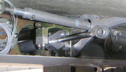
The round thing behind the wires on the left is the outboard fuel level sender. Just to the right of it is the tunnel for the hydraulic flap actuator, which is mounted in the partly-green yoke thing. The tube running across the top of the picture is the aileron pushrod; the aluminum plate is the outboard flap track. The gray thing overhead is the undersurface of the upper wing skin. For scale, the aileron pushrod is 3/4 inch in diameter and the hydraulic actuator shaft is 3/8.
In the meantime, after consulting with a couple of interested friends I have more or less frozen the plan for the master cylinders. The design, which is similar in principle to, but different in detail from, the one I described in the entry for November 4, calls for four master cylinders, one for each flap actuator. All four are connected to a four-armed bellcrank or starwheel; two of its arms are shorter than the other two in order to provide for the difference in extension distance between the inboard and outboard ends of the flap. This assembly is situated under the rear seats. A fifth cylinder drives the starwheel. If you think about this system you will be baffled by the additional cylinder -- why don't the four master cylinders drive the starwheel? -- so it's probably better not to think about it. Bleeder ports in the master cylinders allow the columns of trapped fluid between the master cylinders and the flap actuators to refill on each cycle.
There is still a good deal of work to do to connect the outboard cylinders to hydraulic lines running along the rear spar to the fuselage; there is very little space for flexible hoses in the vicinity of the actuators, but there is enough. I anticipate that installing and hooking up the two inboard actuators will be much more straightforward; they are inside the fuselage, where, theoretically at least, there are no interferences.
[November 24, 2004]
Having lowered the outboard flap actuator pivot pins on both sides to accommodate the actuators in their fully-extended position, I found that they were now too low when the flaps were retracted. I had anticipated this possibility, but had trusted to luck to forestall it. Luck failed me. I do not have an exact drawing of the wings as they really are, and so am reduced to finding dimensions by cut-and-try. It isn't the first time. After some head-scratching I figured out that by moving the point at which the actuator rod attaches to the flap forward about an inch and somewhat downward I could solve the problem. I mocked up a new attachment point on the left flap with phenolic sheet and JB Kwik, but the epoxy hadn't hardened when I had to leave the airport, and so I'm not sure yet whether this solution really is one. Tomorrow being an obligatory at-home day, I won't find out 'til Friday.
On Monday I was supposed to fly out to Mojave to interview Cory Bird about his beautiful Symmetry, which won best everything at Oshkosh last summer. My two motorcycle batteries, which are old and no longer hold a charge well, were too flat to start the engine -- the plane hadn't flown in a month -- but I recharged them and made a short flight later in the day just for the fun of it. An upper-level storm of some kind had passed through over the weekend, leaving snow on the mountains and a mass of cold, transparent and still air over Los Angeles. I climbed to 8,000 feet and meandered around for a while. The air was glassy; the visibility was unlimited in every direction; the engine seemed particularly smooth, the airplane particularly stable; the day was made for flying.
[November 14, 2004]
Last week I began machining the pistons for the flap actuators. I turn them somewhat oversize from a bar of cold-rolled steel, silver-braze them to the stainless-steel shafts, and then finish-machine them with the proper O.D. and an O-ring groove. I have done one so far, and have tentatively assembled one outboard actuator. The actuator pivots in a kind of yoke at the rear spar; its fore end is inside a 3-inch-diameter tunnel that projects forward from the rear spar about a foot into the fuel tank . On fitting the actuator to the wing I found that despite my drawings the rod end that connects the shaft to the flap was still too high up when the cylinder had used up its angular travel within the tunnel. Consequently I had to lower the pivot pins on the yoke, a task that was complicated by there being insufficient material on one side of the yoke for the new hole. I got around this problem on the left side of the airplane; I assume it will be repeated on the right, but I haven't checked yet. Next week's tasks include adding attachment lugs to the left flap for the actuator rod end, repeating the whole actuator-fitting procedure on the right side, making more pistons (four are required), and, time permitting, roughing in the mounts for the inboard actuators, which are inside the fuselage. I feel a nice momentum building.
[November 4, 2004]
How the flaps work:
The inboard ends of the flaps extend 14 inches, and the outboard ends nine and a half. The ends of the flaps must be at the same relative points in their travel at all times during extension and retraction, and the right and left flaps must extend in step with one another. The current design iteration for the flap hydraulics does away with the original idea of slaving the outboard actuators to the inboard ones. Instead, two pairs of tandem cylinders (double-acting cylinders mounted end to end on a common shaft), situated inside the fuselage, serve as master cylinders. During flap extension they vent fluid to the two actuators (inboard and outboard) on each flap. Because the two sections of each tandem unit have the same bore diameter and share a common shaft, they displace identical amounts of fluid, and so their respective slave actuators on the right and left sides will move at the same rate. The tandem cylinders are physically identical, but by connecting their shafts to a common rocker arm at different distances from a fulcrum the ratio of their rates of motion can be controlled and even finely adjusted. During flap retraction, fluid flows from the pump directly to all four actuators, but the mechanically linked master cylinders, now on the downstream sides of the circuits, still preclude their getting out of step. Master cylinders 2.5 to 3 inches in diameter would need to move less than 3 inches to produce the required flap travel.
The
only significant failure mode that I foresee
with this arrangement is leakage, either in any of the four lines
connecting a master cylinder to an actuator or past the piston O-rings
in any of the cylinders. A rapid leak is unlikely, but would be serious
if the pilot or some as yet uninvented automatic monitoring system
failed to take note of it and stop the hydraulic pump. Slow seepage is
more probable, and could cause one end of a flap to fail to extend
fully. It may be necessary to provide a tee and a small manual valve in
each line that would permit fluid from the reservoir to enter the line
while the trailing edges of the flaps are being pushed forward at both
ends. Melmoth 1 had such a system; it required attention every few
weeks.
[November 1, 2004]
While away for a week of camping in Death Valley, I mulled over various ways to keep the two flaps in step with one another during extension and retraction. Interferences have bedeviled my tentative solutions to this problem, most of which involve a cable loop in a figure-eight shape. I had recently investigated hydraulic flow dividers, and decided that they were probably unsuitable because, according to one website, they are only good to within 10%; I then sketched a homemade valve, mechanically linked to the flaps, that would proportion flow in response to inequalities in their positions. The proportioning valve idea made me nervous, however, because it seemed likely to oscillate at some characteristic frequency. Today while driving -- I do a lot of design thinking while driving -- I hit upon a new, simpler solution that I think is a good one. I would like to think that it's ingenious, but it may be that I'm just stupid to have taken so long to come up with it. I now feel that I can start working on making the flaps operable -- probably a more interesting project than the nosewheel doors or the cowl flaps.
[October 21, 2004]
Various minor modifications to the baffles have not yet yielded any substantial changes in the CHTs. I did climb to 11,500 yesterday and get a speed point: 179 kt at 9.7 gph. This was at 29.5/2,400 and peak EGT. It suggests an equivalent flat plate area a little smaller than I had supposed, but it is impossible to make very precise estimates because there is no way to know the specific fuel consumption or the prop efficiency -- that is, no way to know how much power 9.7 gph actually represents.
Noting, after I had shut down, that I had once again forgotten to retract the speed brake after landing, I decided to put other tasks aside for a few days and install a brake extension warning light. It would be bad to try to take off or go around with the brake extended. I also have an idea of how to add a simple mechanical airbrake position indicator using a short length of bicycle brake cable.
[October 18, 2004]
Yesterday I reviewed a pre-World War II report on cylinder baffles, and was reminded that one factor in their effectiveness is the width of the opening through which high pressure air reaches the cylinder fins. The optimum angle is about 145 degrees. Now, the #1 cylinder, which is the hottest, is unique in having a somewhat larger opening than that. I am going to try extending the baffle behind the cylinder in such a way as to confine the flow more. This is a complete stab in the dark. I am also experimenting with closing up the air outlets on the low pressure side (potentially on all cylinders) in order to keep the air in contact with the fins for a slightly longer time. I did this to one cylinder so far, the left middle one, because it and the right middle tend to have the same temperature. On a very brief test flight today the restricted cylinder appeared slightly cooler than the other, but because of weather I did not go high enough or fly long enough to reach stable cruising temperatures. In fact the #2 CHT never even got into the green.
[October 16, 2004]
The NACA flush engine air inlet continues to be highly satisfactory. I have not yet climbed up high enough to map the MP vs rpm boundary, but it seems as though I can now cruise at any non-oxygen altitude without having to run at 2,500 rpm continuous to generate enough MP. I have been cruising back and forth to Mojave at 7,500 feet at around 55% of power, using 2,100 rpm and 27 in. Hg. Fuel flow is 7.8 gph and IAS is 136 knots, TAS 156. I do not seem to be able to get much above 20 nmpg.
I have begun working on the nosewheel doors. It is not yet clear how I will open and close them, but there are so many different ways to do it that one or another of them is bound to work. It is also not clear that closing up the well will reduce drag much; Hoerner gives a rather low coefficient for the drag of sealed cavities. But is seems aesthetically unsatisfactory to leave a huge hole in the bottom of an otherwise fairly clean-looking airplane.
I flew over to Catalina Island the other day for lunch and found that they have upped the landing fee to $20. Too bad; jokes about $100 hamburgers notwithstanding, there are limits to what one will cheerfully pay for a quite average lunch.
By the way, here is the current appearance of Melmoth 2:
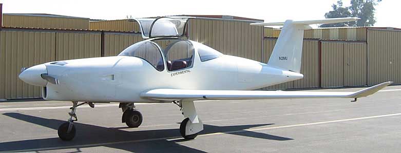
As cool weather approaches, the matter of the cowl flaps gains prominence. The engine cools too much during descents, even with the airbrake. Before reducing the cooling flow, however, I have to deal with the big temperature difference between cylinders 1 and 6, and all the others. I am still waiting for the light to go on there; I can't see yet why #1, the right rear cylinder, should be 90 deg F hotter than 2, 3 and 4. Presumably there is something bad about the configuration of the baffles, but at the moment it still has me, well, baffled.
[September 27, 2004]
Flight tested the NACA scoop today. Luckily, it shows obvious improvement over the previous inlet; at 10,000 ft. and 2,300 rpm, I get four or five more inches of manifold pressure than before. This does not prove the inlet is particularly good; only that it is better than the old one, which may have been particularly bad. But at any rate the additional pressure means additional speed at altitude, or the ability to operate at lower rpm.
Another improvement came from the experiment of lining the inner surface of the cowling side with aluminum foil. After landing, the outer surface of the lined portion was merely warm from the radiant heat of the exhaust and turbocharger, whereas it used to be almost too hot to touch.
The NACA scoop is integral with the side panel. A gasket of felt weatherstripping presses against the open end of an aluminum box covering the air filter.
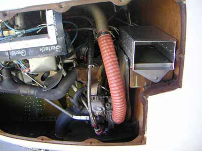
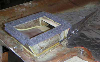
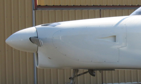
[September 17, 2004]
After finishing the wing root fairings, I had intended to move on to the nosewheel doors. But I found myself dawdling in a way that suggested a certain lack of energy and enterprise, or perhaps anxiety over not having yet done all my homework with respect to the actuating mechanism, and so I turned to some simpler tasks. I improved the lip contour on the cabin air inlet (that should produce no dicernible change); built an attractive balsa wood fairing around the inlet scoop for the battery box blast tube, which now resembles a small gun port embedded in the cowling; and I set to work to install the flush engine air inlet in the left side of the cowling that was the motive for the tuft tests of a couple of months ago. The airplane is unflyable while I work on this, so I'm trying to get it done quickly. Perhaps I am too pessimistic, but I suspect that the difference here, too, (due, in theory, to reduced duct losses and lower induction air temperature) will be imperceptible. But I would never know if I didn't try it. And yes, I did read that recent article in Flying saying that NACA scoops are not much good.
[September 10, 2004]
I devoted the first week back from vacation to finishing off the wing root and boarding step fairings, thereby eliminating four unsightly holes in the surface of the airplane and replacing them with some rather sloppily painted white surfaces, viz:
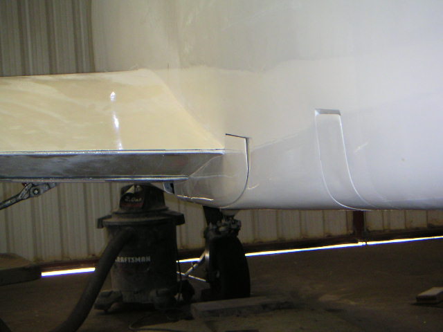
[August 5, 2004]
I returned yesterday from the Oshkosh trip. The airplane performed well, flying 22.5 hours without a mechanical glitch and using about two quarts of oil. The longest leg was 6.5 hours from Fort Wayne, Indiana to Tucumcari, New Mexico via the southeast corner of Missouri (to get around a line of thunderstorms). Overall fuel consumption, including taxi and climb, was 9 gph with airspeeds of around 170 knots. I run 25-50 deg lean of peak, and on the final leg (Santa Fe to Whiteman) I was cruising at 166 ktas at 15,000 ft density altitude using 8.3 gph.
At the start of the trip I set the voltage regulator at 27 volts and the battery was well-behaved, maintaining a charging rate close to zero. In spite of all going well, however, I did make a list of things that need changing, including my silly placement of the pilot's fresh air vent at the center bottom of the panel, where it blasts any chart you try to unfold in front of you.
Oshkosh seemed quieter this year, with far fewer visitors than last and not much in the way of exciting new airplanes (at least ones within the reach of non-millionaires) except Cory Bird's impeccable Symmetry, which carried off all awards for which it was eligible.
[July 27, 2004]
I left for Oshkosh at 7:00 a.m., but soon noted that the temperature in the battery box was higher than I had ever seen it -- 55 C -- and the charging current had gone straight to 4 amps. Concerned about possible thermal runaway, I turned back after going only 70 miles. I spent the rest of the day talking with people about the problem and trying to figure out how to solve it. Eliding a number of tedious details, it is sufficient to say that the higher-than-normal temperature was probably due to my having replaced a leaky gasket where the turbocharger joins the exhaust collectors. This raised the temperature (I am guessing) of the exhaust pipe whose proximity is the principal cause of heating in the battery box. Until I decide to lag or otherwise shield that pipe, it seems as though the box will inevitably be rather warm. Warmer batteries have lower resistance and therefore accept more charging current, which tends to heat them even further. The newly-installed blast tube at least maintains equilibrium, as appears from the fact that the temperature held steady at 55 and dropped when I reduced power.
I realized later in the day that I could perhaps lower the charging current, and thus the amount of heat I am putting into the battery in the form of electrical energy, simply by lowering the system voltage. The voltage regulator is within easy reach in the cockpit, and there is nothing magical about the number 28. Twenty-six or 27 volts would do as well. So tomorrow morning I will again depart, armed with a somewhat improved (though still, for all I know, imperfect) understanding of what is going on with the battery.
Before turning back I had established a 146 kias cruise at 28/2500 at 12,000-ft density altitude, for a TAS of 174 knots, using 9.3 gph. This is a fairly typical performance point.
[July 21, 2004]
I've been working on a few modifications before leaving for Oshkosh. As usual, I began the least important one first, and it's taking far longer than expected. The things I was hoping to accomplish were to 1) add fairings at the wing root trailing edges, covering the flap tracks; 2) provide a small external air scoop to ventilate the battery box; 3) replace the long duct bringing intake air to the filter with a NACA scoop in the side of the cowling; 4) add a short diagonal brace to the nose gear half-fork to make it stiffer in bending and torsion; and 5) wash the airplane. It's becoming increasingly apparent that I'll be lucky to get the fairings contoured, but not primed or painted, and to ventilate the battery box.
[June 26, 2004]
I flew to San Luis Obispo to meet a friend who was traveling to Los Angeles. She had 184 pounds of baggage, which pushed the CG farther aft than it had ever been before, to 34.6% of chord. This is still well ahead of the aft limit, and, more to the point, represents an aft moment (ie, the lift that must be supplied by the horizontal tail to keep the airplane balanced) only about half as large as would occur with two 170-pound back seat passengers and 50 pounds of baggage. To my surprise and chagrin, however, I found that I ran out of nose-down trim just at cruising speed. The elevator deflection was very slight (the tail loading was only 2.4 lb/sq ft, even ignoring the nose-down contribution of the wing pitching moment), so it is not a question of lack of tail power, but rather of lack of trim authority. Now, it happens that the nose-up trim is also insufficient to trim for approach speed at forward CG. What limits the trim authority at both extremes is the fact that the trim tabs are also servo tabs, intended to reduce pitch control forces. The pitch forces are currently so light, however, that I could perhaps eliminate the servo function and use the tabs for trim only; that would greatly increase the available trim authority.
[June 11, 2004]
I flew to Mojave for lunch and also to record tufts on the top of the cowling. The tufts showed, as expected, some turbulence behind the outlets, growing more severe as the flow approaches the windscreen and the boundary layer thickens. It may be due to several factors. One that I have already identified is the very steep sweep angle of the outlets -- about 35-40 degrees. The streamlines on the turning vanes tend to align themselves with the leading edges of the vanes, and so the air emerges at an angle to the external flow. Shearing where the internal and external flows meet creates vortices. I suspect that the disturbed flow may re-stabilize itself as it accelerates on the windscreen, and so the ultimate drag penalty may be small, but until I install the final moveable outlet vanes there is no "actionable intelligence" to be taken from the present observations. There is also a larger unanswered -- and perhaps unanswerable -- question about whether the benefit of the forward outlets (see Cooling Flow) at the angles of attack actually encountered in real-life climbs justifies their existence at all. Two noteworthy things about the tufts are that the ones just outboard of the outlet wakes are straight and steady, and that there is no evidence of slipstream rotation (which I have always suspected of being a figment of someone's imagination anyway).
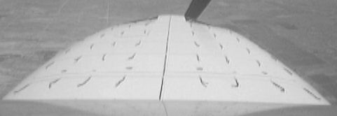
In the course of a conversation about induction air inlets someone suggested that it might be good idea to adopt the old Mooney approach of a pilot-selectable air filter bypass for the air entering the NACA scoop at high velocity. I don't know why this option, with which I have been familiar for about 30 years, didn't occur to me before, but now I'm thinking about bifurcated duct through which the engine would breathe filtered air from the cold plenum on the ground and unfiltered air directly from the NACA inlet in flight.
In case you don't feel like reading all the stuff below to find out what the induction problem is, it's basically that air enters the planned flush scoop on the cowling at about 300 feet per second, and it would enter the turbocharger at about 300 feet per second, but in between it would have to slow down to less than 30 feet per second to pass through the air filter (because the area of the air filter is more than ten times the inlet cross-section). Now, you lose a lot of the energy of the airstream unless you decelerate ("diffuse") the air in a very long and gradually expanding duct, for which there is obviously not room in the cowling. A well-designed filter bypass would let the air flow straight to the turbo inlet through a smooth duct little more than a foot long. It still isn't ideal; it has to make two 90-degree turns on the way. But the losses may still be less than in any of the alternative arrangements I've been able to think of. Also, any ram recovery, which is pretty much nonexistent in a filtered system, can be doubled or tripled by the turbocharger, and so might be worth trying to get for high-altitude flying. It's very difficult, however, to get good ram recovery from a flush NACA scoop over the full range of speeds, power settings and air densities encountered by a turbocharged airplane.
[June 3, 2004]
A couple of frames captured from some 40 minutes of in-flight videotape convey the essence of the information acquired, and also illustrate rather nicely, if it needed illustrating, the curved path of the air over the wing. The vertical white bar is an artifact of the camera, due to sunlight reflecting from the canopy.
The area of interest, so far as the engine air inlet is concerned, is at the left edge of the picture; in fact, it's just the first three columns of tufts, and the region immediately below the continuous black line, which is a horizontal reference. The rows of tufts are four inches apart vertically and roughly (not exactly) ten inches apart horizontally. The tufts immediately above the reference line are one inch from it.
The first image is during a 100 kias climb. The angle of attack is about three degrees, and the tufts in the inlet area are tilted upward at about that angle.
For comparison, here s the CFD prediction of streamline paths at an angle of attack of four degrees:
The image below is in cruise at around 140 kias; the tufts are now parallel to the horizontal reference line.
On
a subsequent flight I tufted only the vicinity
of the proposed inlet, and provided not only a horizontal reference but
also a 10-degree angle reference which is visible as a faint extension
behind the uppermost of the three tufts. This
image (unfortunately none too clear), taken at the moment of touchdown
in a full-stall landing, flaps up, shows how closely the flow in that
area tends to match the flight path vector; the apparent angle of the
tufts is somewhere around 12 to 15 degrees, which is about the expected
angle of attack of incidence of the airplane at touchdown.
This
image (unfortunately none too clear), taken at the moment of touchdown
in a full-stall landing, flaps up, shows how closely the flow in that
area tends to match the flight path vector; the apparent angle of the
tufts is somewhere around 12 to 15 degrees, which is about the expected
angle of attack of incidence of the airplane at touchdown.
Whatever its intrinsic interest, all this effort to discover the local flow direction may have been mooted by my having stumbled, after repeated Googling of various combinations of NACA, submerged, flush, intake, inlet and scoop, upon a 1948 NACA Research Memorandum, A8B16, which states unequivocally that the influence of angle of attack upon the pressure recovery of a fuselage-side flush scoop is slight. On the other hand, another RM (A50E02) states that ram recovery diminishes with increasing angle of attack, but attributes this effect not to misalignment of the scoop with the flow, but rather to increased boundary-layer thickness. An even earlier report (Advance Confidential Report 5I20, from 1945) cautions that submerged inlets "do not ... have desirable pressure-recovery characteristics for ... oil coolers, radiators, or carburetors [because] the required diffusion of the air and the range of inlet-velocity ratios is too great..." In other words, a given NACA scoop works well only in a narrow range of flow rates, whereas pitot or ram-type scoops -- ones whose openings face directly into the wind -- can recover a large portion of free-stream dynamic pressure regardless of the amount of flow actually being admitted. On the one hand, therefore, an airplane that operates most of the time quite far from its maximum-performance points ought to have ram inlets; but on the other hand the turbocharger easily overcomes a small ram-pressure deficit, and the flush scoop has the advantage of minimal drag. Voters in the impending election might do well to reflect that "on the one hand ... on the other hand" may indicate not a waffling personality, but rather a realistic appreciation of the compexities of a situation.
[May 28, 2004]
Okay, the MB antenna worked fine, so that takes care of that.
One of the next projects on my list is to replace the long duct through which the engine is currently breathing with a flush inlet in the side of the cowling, close to the air filter and the turbocharger. At the least, this should bring the temperature of the inlet air down somewhat, and may improve the ram recovery. Sizing the inlet is a fairly simple matter of identifying a few performance points -- maximum rate of climb at 10,000 feet, for instance, or maximum cruise at 18,000 feet -- that might represent the highest rate of airflow to the engine, which inhales 1,300 pounds, or around 16,000 cubic feet, of air per hour at 2,800 rpm in its naturally aspirated form and a third more with 40 in. Hg manifold pressure. I concluded that an inlet area of 7 square inches, with dimensions of 5 x 1.4 inches, would be about right.
What is more difficult is determining the best orientation of the inlet. The range of fuselage incidences that are of interest is about 1 to 4 degrees. Unfortunately, I haven't been able to locate any information on the effect of misalignment on the pressure recovery of flush NACA scoops, though I have a faint recollection of having read somewhere that misalignments of 3 or 4 degrees are tolerable. My CFD software can predict streamline paths on the cowling, but to verify them I attached a small TV camera to one of the flap tracks, tufted the fuselage from the nose back to the aft end of the canopy, and recorded a flight with speeds of 80 to 150 kias and with the speed brake open and closed. The results confirmed the CFD predictions, and also showed no flow separation on the fuselage sides even at low speed, except with the speed brake out. This result encourages me to think that no wing root fillets will be needed -- the hoped-for effect of making the intersection between the wing upper surface and the fuselage a right angle and of having the maximum width of the fuselage coincide with the trailing edge of the wing. I was likewise relieved to see that while there is some loss of flow energy in the stupidly designed intersection of the fuselage and the aft canopy, it's slight and probably doesn't have much effect on performance.
All this research to find the best orientation for an air intake is in a sense quite silly. The extreme performance points are in any case seldom visited except during flight testing; furthermore, any reasonably forward-facing inlet of roughly adequate size will work fine, and besides, you never really know how good an inlet is because, at least with a project like mine, once you have arrived at a satisfactory solution to a problem you don't go on endlessly investigating alternatives. For that matter, there are so many other variables involved in engine breathing that the last degree of refinement in the inlet orientation may be overshadowed by some unsuspected (or, for that matter, suspected) deficiency elsewhere in the system. The main reasons for making a study of the duct environment are three. First, it's amusing to mess around with airplanes, and this is one form of messing around. Second, it will provide a pretty good idea of the the correct orientation for the inlet. Third (and this may seem identical to the second, but really it is somewhat different), it may prevent making some grotesque error in orientation and placement that would otherwise become obvious only in retrospect.
This was the first time I've used the tiny television camera, which cost $100 and plays into a digital camcorder in the cockpit, in flight. Sooner or later, I plan to use it to confirm proper closing of the wheel well doors, sealing of engine baffles, and flow patterns inside the cowling.
[May 23, 2004]
On Friday I added a marker beacon antenna -- a dipole consisting of two pieces of copper tape nearly a yard long -- under the floor beneath the back seats. That makes a full ILS. I haven't tested it yet, but will tomorrow. I assume it will work because the marker beacon is the least demanding of all the radios, receiving a single frequency at short range with the signal arriving from directly below, where no part of the airframe gets in its way.
A few days ago somebody said something about aft loading, to the effect that the basic criterion was that if the airplane were tipped back until its tail touched the ground, it should drop back onto its nosewheel. Some won't. I suddenly wondered whether I had ever made that simple calculation. Last night I did, and was relieved the find that at the aft limit, which is at 50% of chord (FS 126.4), the CG is still nearly two inches ahead of the main gear axles when the airplane is tipped 15 degrees nose up. Whew.
[May 20, 2004]
In the past couple of weeks I changed the oil; installed a new heat shield on the batteries; added a stall warning bleater; reinforced the left front engine baffles to prevent them from lifting under air loads; replaced the voltage regulator; put a ventilating valve from a Camry on the passenger side and made a duct to it from the NACA inlet on the right side of the fuselage; installed a 12-volt cigarette-lighter-style outlet for external gadgets like a handheld GPS; and installed a glideslope antenna in the left wing. A brief test flight this afternoon revealed the flow from the ventilator to be rather anemic. The glideslope seemed to work fine, however, as did the 12-volt outlet. I failed to notice the battery charging current, and so I don't know yet whether the replacement regulator solved that problem or not.
The glideslope antenna was a rather simple addition that took a couple of hours to do. I used two pieces of solid copper wire, probably 16 gauge or so, taken from a piece of household cabling. There is a recess in the leading edge of the wing to accommodate the Safe Flight angle-of-attack indicator. The leading edge is fiberglass over a foam core back to 5% of chord, where the carbon wing box-cum-fuel tank begins. I was able to poke the wires into the foam to the right and left from inside the recess, and connect them to a coax which I brought out through the same conduit as carries the angle-of-attack sensor wiring.
The 12-volt outlet is powered by both channels of a Narco MP-10 power converter; it can supply up to 2 amps.
[May 7, 2004]
The revised fuel system plumbing worked, and did seem to reduce rough running due to fuel heating.
On May 1 I flew to Flagstaff to join a camping trip of the primary school that my children formerly attended. In the course of that trip the battery began drawing an increasing charging current, even when I would have expected it to be fully charged. On landing I found the battery water somewhat depleted, but whether that was a cause or a consequence of the excessive charging I didn't know. The problem recurred on yesterday's interminable (headwinds, moderate turbulence) trip from Flagstaff to Livermore by way of Lancaster. A couple of people have suggested that a shorted cell in one battery (I use two 14-volt batteries for the 28-volt system) could be the cause.
Forty-five minutes out of Livermore I observed the fuel flow to be rising while the peak EGT dropped. Smelling no fuel, I assumed that whatever was wrong it was not a fuel leak, and I continued on to Livermore. There I found that a loose B-nut on the fuel pressure line to the panel was allowing fuel to spray all over the inside of the cowling, accounting for both high indicated fuel flows and low delivery of fuel to the cylinders. I fixed it this morning and returned to Los Angeles without further incident, though I took the precaution of shutting down the electrical system for most of the flight because of the continued peculiar behavior of the battery.
For reasons that I don't know, the CHT probe on the #1 cylinder (right rear) emerged from a long dormancy to reveal that that cylinder, not #6 (left front), as I had always thought, is the hottest. Equal CHTs still elude me.
I found on descending into Livermore that very high rates of descent (> 2000 fpm) are possible with the airbrake, and that the buffeting I had experienced at lower speeds disappears above about 140 kias. All the more reason that a brake position indicator would be desirable.
I measured a temperature rise of about 40 deg C above ambient in the air entering the oil cooler, owing, I assume, to the exhaust pipes and turbocharger. It appears that an insulated duct running within the cowling from the air inlet to the cooler might help bring down the oil temperature, which currently hovers around 97 deg C.
[April 22, 2004]
One of the chronic problems associated with updraft cooling has been rough running while taxiing for any length of time on hot days or after landing, when the heat rising from the engine would boil the fuel in the lines. Having been designed with downdraft cooling in mind, the engine has its throttle body, distributor block, injectors, and all the associated plumbing on the top. Engine heat soaks into them through conduction, convection, and radiation -- no avenue has been omitted. This week I revised the system, moving the distributor to a position below the front of the crankcase, just within the cowling air inlet. The throttle body remains atop the engine, as do the injectors, but everything else is now underneath. I hope this will solve the problem. Tomorrow I will do a long ground run with the cowling on; I'll flight test it on Monday.
[March 19, 2004]
I had lunch at Mojave with Mike Melvill. I mentioned the peculiar asymmetry of dihedral effect that I noted when I first flew with the canted wingtips. Mike quickly asked whether the rudder moved at the same rate, in proportion to pedal displacement, to the right and to the left. We then realized simultaneously that the geometry of the connection between the rudder pedals and the pulley that drives the rudder cable (with which he is all too familiar, having gallantly repaired it after it fell apart during some of his kick-and-punch flutter testing) was more likely than not non-symmetrical, and that this, rather than some mysterious aerodynamic or power-related phenomenon, was the probable cause.
[March 11, 2004]
I've spent several hours contouring the tips and am nowhere near finished. "Contouring" means coating the bare composite skin with microballoon-filled epoxy and sanding it down to a smooth, well-shaped surface. This is not difficult on ruled surfaces like wings and on generally convex or mildly concave ones like fuselages, but I find it very difficult on surfaces with rapid shifts from convex to concave curvature, such as occur in the curved transition from the tip panel to the wing. I will undoubtedly lose patience at some point and settle for a less than perfect result.
In the meanwhile I've been occupying my thoughts with several other projects, including front-seat armrests (a pretty simple matter) and a separate air intake for engine breathing. The air intake seems desirable because I've found that air taken in at the front cowling inlet picks up quite a bit of heat on the way back to the turbocharger. There are ducting losses as well. I polled a few people about how best to handle the transition from the small intake cross-section (about 8 square inches) to the air filter, which is more than ten times larger. The consensus seemed to be that lack of space makes an ideal diffuser impossible, and the best bet is just to spill the intake air directly into a plenum and live with the inevitable losses. I considered both recessed ("NACA scoop") and protruding ("pitot") inlets, and decided to use the recessed type, even though it may have slightly lower ram recovery, because it produces less parasite drag. Ram recovery would weigh more heavily with me if I planned to do a lot of flying at maximum speed and altitude, like an interceptor; but I don't. Quite a lot of mulling has gone into the details of this ostensibly simple modification, because the scoop will be in the left side panel of the cowling, which must be easily removable.
I've also been revisiting the design of my middle flap track. (The flaps are installed, but not yet operable.) I need to remove the wings briefly for various reasons, and while they're off I'm intending to reinforce the area around the middle track attachment.
Reinforcing the middle flap track attachment points requires knowing the air load acting on the flap. CFD analyses indicate that the load on a fully-deflected Fowler flap is quite constant over the useful angle-of-attack range because the local angle of attack is controlled by the wing, while the total load on the wing+flap combination naturally increases with angle of attack, or "alpha". As a result, the fraction of the total load borne by the flap increases as speed increases, going from 13% at +10 degrees alpha to over 35% at -5 degrees (the angle of attack for maintaining 90 knots, the design flap speed, at minimum weight). The air load on the fully-deflected flap is always about 350-370 pounds per flap,. (The area of the flap, by the way, is 9 square feet, that of the wing panel 44 square feet.)
A source of Fowler flap test data is NACA Technical Report No. 534, which reports that the air load on this type of flap -- which translates aft until its leading edge coincides with the trailing edge of the wing before deflecting downward, in this case, 30 degrees -- rises to "nearly 1.5 times the load that would result from uniform distribution of the total load over the total area." Taking "total area" to mean wing+flap and omitting the portion of the wing that is buried in the fuselage, at a 2,850-pound gross weight the average loading would be 1425/(44+9) or 26.9 lb/sq ft. The flap load would then be about 40 lb/sq ft, or around 360 lbs. What a coincidence. The same NACA TR also says that the maximum CL of the flap itself may go as high as 3.2; at 60 knots, that would put a 350-lb air load on each flap. Bingo!
Part 23 requires that a flap be designed for a maneuvering load factor of 2G and for 25 fps gusts either normal to or aligned with the flight path. The 2G maneuvering requirement is equivalent to pulling up to the stalling angle of attack while at 85 knots; increasing the angle of attack reduces the fraction of the lift carried by the flap, however, and the flap load remains unchanged. The normal gust would change the angle of attack by 15 degrees, which would have the same effect of driving the wing up to the stall. The gust parallel to the flight path, on the other hand, is an increase in airspeed without a change in angle of attack. Part 23 requires that Vf, the flap extension speed, be the greater of 1.8 times the flaps-down stalling speed and 1.4 times the clean stalling speed. My 90-knot value does not meet this criterion, nor is it required to, this being a homebuilt. The worst case for gust loading, however, is the minimum speed, not the maximum, because the change in dynamic pressure, a function of the square of speed, is proportionately greater. Adding a 25 fps horizontal gust to the 60-knot stalling speed increases the air load on the flap by 56%, to 560 pounds. A factor of safety of 50% brings the ultimate load requirement to 842 lb per flap, half of which is carried by the middle track, with the remainder shared more or less equally between the inboard and outboard tracks.
[March 1, 2004]
That "end of next week" estimate with which I ended the last entry was my usual self-deception. I never learn.
The wingtips were an unexpectedly long process. First Ray Henning and I hotwired styrofoam cores for the upward-canted, straight-tapered portions. I laid up 2-ply bidirectional skins on the undersides of the cores. I then bandsawed wedge-shaped styrofoam inserts about three inches wide and 21 inches long, and bonded them to the roots of the tapered segments to provide 30 degrees of tip cant. I then bonded those assemblies to the wing, relying on measurement and on the accuracy of the insert surfaces to jig them, and carved and sanded the curved transition to shape. I then laid up bridges from the wings to the cured bottom skins of the tapered portions, incorporating little NACA scoops for the fuel vents and tunnels for access to the outboard aileron hinge bolts. Finally I skinned the tops. Each wingtip thus required five overnight cure cycles, and since I did the two tips one after the other (in order to avoid making any fatal errors twice), the whole project took two weeks. They still need to be filled, smoothed and painted, but they are flyable as is.
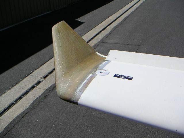
Theoretically, the tips should increase the dihedral effect of the wing alone by 50%; their effect on the totality of the airplane is more difficult to analyze. The additional wingspan should increase the L/D ratio by about 5% (from 15.1 to 15.9) and rate of climb by about 1%. John Thorp once told me that shedding the tip vortex from the ailerons increases stick forces; and so there was some basis for expecting a reduction in roll forces by moving the tip vortices outboard.
Today I made a 20-minute test flight to get a subjective assessment of the effect of the tips. It's impossible to detect small differences in rate of climb or L/D ratio, and roll forces seemed about the same as ever (too high). On the other hand, roll-yaw coupling is definitely improved. I am puzzled, however, by the fact that most of the improvement is found when yawing and rolling to the left; the dihedral effect with right yaw is considerably weaker. I don't know why this would be, and several minutes of standing in front of the airplane and scratching my chin did nothing to enlighten me.
[February 13, 2004]
 I'm in the
process of adding wingtips. The wings
were originally designed for a span of 420 inches (35 ft, 10.67 m), but
I left 10 inches off each end to allow tailoring the dihedral effect by
canting the tips. Without the tips, the airplane has barely positive
dihedral effect; that is, it rolls only slightly in response to rudder.
The tips, which will in fact increase the span to 430 inches (35.8 ft,
10.92 m), are canted upward 30 degrees and have about 45 degrees of
leading edge sweep. Both the upward cant and the sweep are supposed to
contribute to the dihedral effect, for reasons that are fairly obvious
if you consider that the desired rolling moment results from sideslip.
It will be interesting to see whether they actually do. Something
similar was done to improve the dihedral effect on Rutan's White Knight
(the suborbital rocket's mother ship) and it was quite successful. I'm
not certain that the rapid taper to a 6-inch chord NACA 0009 section at
the tip is a good idea; White Knight's tips are broader and cambered.
I'm in the
process of adding wingtips. The wings
were originally designed for a span of 420 inches (35 ft, 10.67 m), but
I left 10 inches off each end to allow tailoring the dihedral effect by
canting the tips. Without the tips, the airplane has barely positive
dihedral effect; that is, it rolls only slightly in response to rudder.
The tips, which will in fact increase the span to 430 inches (35.8 ft,
10.92 m), are canted upward 30 degrees and have about 45 degrees of
leading edge sweep. Both the upward cant and the sweep are supposed to
contribute to the dihedral effect, for reasons that are fairly obvious
if you consider that the desired rolling moment results from sideslip.
It will be interesting to see whether they actually do. Something
similar was done to improve the dihedral effect on Rutan's White Knight
(the suborbital rocket's mother ship) and it was quite successful. I'm
not certain that the rapid taper to a 6-inch chord NACA 0009 section at
the tip is a good idea; White Knight's tips are broader and cambered.
I hope to test-fly the tips by by the end of next week.
[February 5, 2004]
I flew up to Mojave to do a series of landings with the airbrake open, but since the first one was perfect and showed no detrimental effect, I cancelled the rest of the test. It was a classic mild California winter day of blue skies and unlimited visibilities, both at Whiteman and at Mojave; lovely for flying. I noticed on departure that at climb power the engine cools better at lower speed -- that is, better at best rate of climb speed than at cruise climb speed. I attribute this oddity to the extraction effect of the foward outlets.
I added a capsule assessment of the cooling system to the essay on cooling flow.
[February 2, 2004]
My planned test flight last Friday didn't happen, because of a stomach flu. I finally got in a 45-minute flight today, before the current rainstorm arrived. The results were generally good. The heater works, and doesn't smell bad. The new rudder trim tab seems just right; the ball is now centered in cruise, whereas it used to be a tad out of the cage to the left. The #2 comm antenna, using a design suggested by Allen Podell, works much better than the #1 comm's copper-tape dipole in the leading edge of the fin. The aft edge of the top cowl now stays put regardless of the airspeed.
On the other hand, the deflector that I put into the cowling behind the air inlet in the hope of steering some extra air toward the #6 cylinder seems to have had no effect at all; that cylinder is still 20 deg. C. hotter than the others (190 v. 170) in cruise.
I tried landing with the airbrake open; it seemed as though the airplane was less stable laterally and directionally and harder to control in the flare, but I'll have to do it a few more times to be sure.
I measured the air temperature inside the cowling on top of the air filter box; it's 20 deg. C. above ambient. Next flight I'll measure the temperature inside the air box; if there's no difference, then I can get rid of the long SCAT hose bringing air from just behind the inlet back to the filter, which is against the firewall. I've been toying with the idea of putting a dedicated NACA inlet on the cowling side to feed the engine, but I haven't yet decided whether it's worthwhile and, if so, where the inlet should be. I'll have to change something eventually, because I know that the present duct is not large enough to supply the engine at critical altitude.
[January 25, 2004]
The heater is now installed, but still untested, so I don't know how effective it is, and probably won't know until some future flight in semi-dark subfreezing weather when I find out that what seemed adequate on a southern California afternoon really wasn't. It was not much trouble to build, but I may regret using .010 aluminum for its outer shell.
The number of to-do items that I can reasonably undertake before being obliged to deal with the flaps grows ever smaller.
[January 16, 2004]
I flew to Santa Fe on the 12th and returned on the 14th. It was a lucky choice of dates. A high in southern Arizona put 15 knots on my tail for the eastbound trip. Two days later the high had migrated into Utah and a low had established itself in northern Baja. Together they were squirting air back toward California, against the current. I averaged 180 knots going, takeoff to touchdown, and 184 coming back. The trip somewhat made up for the fact that in this imperfect world the majority of wind components are inevitably negative.
The airplane performed perfectly, except in two respects. First, the cold-soaked engine would not start at Santa Fe; I don't know if this is because the battery is too small, or because it's getting old. Second, it got quite chilly in the cabin when an overcast blocked out the sun. On returning home I immediately moved "add heater" to the top of the to-do list.
An odd thing I noticed after landing was that the fine splatter of oil that I usually find on the windshield after a few hours of flying was not there; nor were there the usual fine streaks of oil on the upper cowling. I cannot account for this change, unless it is related to lower than usual air temperatures, or simply to my having cleaned off the inner surface of the cowling while repairing the outlet lips.
Yesterday I finished installing the additional Camlocs to the top cowling, but I have not yet flown to test their effect. Today I began making a heater. Fortunately I had salvaged all the hard-to-build components from Melmoth I; all I need to do is build a new muff. Heat is taken from a 9.25-inch segment of exhaust pipe; the exhaust systems of turbocharged airplanes, being under pressure, run very hot, and so I expect this to be enough.
[January 8, 2004]
It turns out that the buffet and tailwagging produced by the airbrake diminish with speed to the point that at 100 kias you are not aware that the brake is open; so the warning light is probably a good idea.
I had moved the cowl air temperature sensor from the top of the baffles -- that is, the hot side -- to the bottom, right next to the rocker covers. In cruise the temperature was 21 C (OAT was 12.5 C), which is barely balmy; after landing and during taxi it rose to 42 C, which is just about half of the temperature above the engine. After shutdown, with no airflow in the cowling, however, it rose to 95 C. The sensor is on the left side of the cowling, where the turbocharger is; some of that heat is probably coming from the turbo. I need to get some readings on the right side for comparison.
Mike Melvill once suggested that I might want to install a drop-in door in the rear portion of the top cowl to allow hot air to escape after shutdown. It would close itself under ram pressure. I'm thinking about it.
[January 7, 2004]
Little has been accomplished in the last two weeks, on account of the holidays. I replaced the deformed fairings on the aft cowl outlet lips with balsa-cored ones, which will presumably not inflate to a preposterous shape when heated, as the styrofoam-cored ones did. I also began to install four additional Camlocs in the top cowling; the rear edge, which is under full ram pressure, bulged a little between the original ones. This would not have bothered me much, had the shortcoming not been situated just a few inches from the windscreen, where I was obliged to stare at it continually.
A couple of people asked the obvious question about the airbrake: What is the maximum speed at which it can be used? I designed it for 300 mph indicated; not that I expect ever to get going that fast, but if I did I suppose I would want to slow down as soon as possible.
With regard to the question of whether there ought to be a brake-open warning light or not, I am still undecided. I need to do some basic tests, for instance, to ascertain the influence of the airbrake on stalling and takeoff behavior. I bought a reed relay ($2) that I can, if need be, secure to the structure near the trailing edge of the airbrake and wire to a yellow light on the panel. A small chip of magnet bonded to the brake would trip the relay when the brake is closed, turning the light off.
I'm flying to Mojave tomorrow for the press unveiling at Scaled of the "Global Flyer," a jet-propelled version of Voyager that is supposed to circle the globe nonstop in 80 hours, without refueling, with all-purpose adventurer Steve Fossett at the controls. That will be an opportunity to gain a little more airbrake experience.
[December 17, 2003]
I spent the morning writing the inevitable (for all aviation writers and a few with no understanding of aviation at all) assessment of the Wrights for the local paper. Then I went to the airport, finished the installation and wiring for the airbrake, and test-flew it. It produces a distinct but gradual and perfectly controllable pitch up; the moment generated by pressure under the belly ahead of the wing obviously much exceeds that from drag below the thrust line. With the brake down there is a continuous rumble that should make any kind of warning light or position indicator unnecessary. The effect on descent rate is marked; no official numbers yet, but I think I got rid of 2,000 feet in less than a minute at 125 kias without reducing throttle. There was no discernible small of exhaust in the cockpit. I had removed one of the upper access panels so that I could look down at the airbrake. With it open, there was nothing between me and Valencia but a lot of air. Unfortunately, before I could do much testing one of the cowl outlet vanes sheared a rivet and its trailing edge popped up to an odd position. I returned to the airport at reduced speed.
[December 15, 2003]
Having modified the airbrake lever on the throttle quadrant to incorporate a microswitch that will turn the hydraulic pump on and off, I provisionally assembled the system in order to test it. Concerned that undetected internal leakage in the landing gear control valve might allow pressure from the airbrake actuator to back up into the landing gear cylinders, I put jacks under the wings and immobilized the nosegear drag link hinge with a C-clamp. These precautions turned out to be unnecessary. The brake opened at a good speed -- not too rapidly -- and closed gradually. The purpose of the test, other than to satisfy my curiosity about the basic operability of the whole system, was to determine which position of the control valve was "up" and which was "down." It may seem odd that there was no other way to determine this, but aviation is full of surprises.
[December 9, 2003]
I successfully reworked the backup gear lowering system (see entry for November 20) to get it out of the way of the airbrake actuator. The actuator, a single-acting hydraulic cylinder, is now in place and plumbed; it remains only to connect the brake control on the throttle quadrant to the hydraulic valve, which, like the gear and flap valve, is located under the right seat in a compartment that is accessible both from inside the cabin and, by opening the airbrake, from below. Unfortunately, it is so crammed with stuff that you can barely get a hand into it without drawing blood. Fortunately, my upholstery is maroon. I am using 1/16 aircraft cables running in teflon-lined bicycle brake cable housings to connect the panel controls to the valves. The friction is rather high and I think it would be better eventually to run the cables over pulleys; but for the time being this will have to do.
[November 26, 2003]
Went to Mojave side by side with Tony Bill's Marchetti 260, which is a particularly elegant airplane in flight. It's hard, when two airplanes of similar performance fly together, not to make it some kind of race. He outran me easily on the way out, but, having added a passenger for the trip back and flying at 7,500 feet vs 6,500, couldn't catch me. I was running 30/2500, probably around 75-80% power, vs his 21/2500, but it's difficult to make a direct comparison because the compression ratio of the turbocharged engine is lower. One quite noticeable thing was that when we hit some moderate turbulence I immediately slowed down, whereas he wouldn't have. That's the difference between thinking you have a 6G airplane and knowing that you do.
[November 24, 2003]
At 3,000 feet, OAT 14 C (57 F), indicating 150 kts at 27/2500 leaned to peak EGT, the upper-plenum air temperature was 62 deg. C (144 F) according to the wonderful $29 Radio Shack gadget, whose sole vice is that it starts to beep loudly when it thinks my hamburgers are done. This seems rather cool to me, and suggests that the heat removed from the engine is being diluted in too much air. The cylinder head temps were also in the 170-180 C (338-356 F) range -- somewhat too cold. Continental recommends 370 F (188 C). Now that winter is upon us, I wish I had the cowl flaps working and could choke the cooling flow; but no such luck. I should probably start working on them as soon as the airbrake is operating.
[November 20, 2003]
The revised air box appears to work as hoped. The barbecue gadget, however, quit working on the first flight intended to get data from it. I took it back to Radio Shack, where the guy rubbed the ends of the sending-unit batteries against his shirt and lo and behold it started working again. Why didn't I think of that? The flight took place on an overcast day, and so although the fuel-switching-motor-in-operation LED looked much brighter with its new resistor, I'm still not sure whether it will be visible in bright sunlight. The robot tank switcher is now working fine, but on two occasions I have forgotten to shut it off before landing. This is what checklists are for; you don't want it switching tanks on you on final approach.
The next project is to get the airbrake working. Before I can do that, however, I have to move the actuation point for the backup gear-lowering handle, which gets the gear started back overcenter so that it can free drop. The present interim implementation is connected straight into the main gear-operating bellcrank, which is on the airplane centerline. The hydraulic cylinder that opens the airbrake is supposed to be in the same place, and so in order to install it I have to move the overcenter thing to another location. I'm quite curious to see how the airbrake behaves, whether it causes undue vibration (for instance in the gear doors, which are right behind it), whether it produces a large pitching moment, whether it sucks a lot of exhaust gas into the cockpit, and whether it provides sufficient deceleration and/or rate of descent to justify its own existence.
[November 11, 2003]
Changing the Lord mounts for more compliant ones had the effect of letting the engine settle a bit and also flail around more on startup and shutdown. This caused a problem with the interface between the turbo air inlet and the air filter box. The box is stationary, with an accordion-pleated elastic gland between it and the turbo inlet to allow for engine movement. With the engine in its new position, however, the turbo and the gland were badly misaligned. I decided that rather than try to adjust the engine position (for instance by putting spacers on top of the Lord mounts, which would be permissible), I would revise the air ducting in such a way as to let it accommodate any engine movement at all. For the last few days, therefore, I've been working on a "banjo box" air duct that will clamp directly to the turbo, and be connected to the (much modified) filter box by a flexible hose.
I also acquired a remote thermometer (intended for maniacally gadget-happy barbecuers) at Radio Shack, with which I intend to investigate the temperatures within the cowling. Barring any unforeseen stumbles with the banjo box, M2 should be flying again by the end of this week.
[November 4, 2003]
The oil cooler now works properly. Cruising today at 9,000 feet at 70% power with a 7C (45F) OAT, the OT was 98C (208F), and dropped to 77C (170F), which is the thermostat setting, during descent. That's acceptable. The small change in the baffling on the #6 cylinder had no effect that I could notice on its temperature, which continues to be somewhat higher than the other cylinders'.
On this flight I also tested the high intensity LED that I had installed to let me know when the tank-switching motor is running. It needs more work; it's barely visible in sunlight.
[October 31, 2003]
Today is Melmoth 2's birthday; it was a year ago that the airplane first flew. It has flown 68 hours since, but spent far more hours in the shop than in the air. This is not surprising, since it was frankly unfinished when it first flew. The F-15-like ratio of maintenance and modification time to flight time will persist for another couple of years.
I did not fly today, however, because I was busy installing a panel light that will indicate when the tank-switching motor is running. This naturally took longer than expected. I started off with a red LED, then reflected that red should be associated exclusively with danger items, and went to the store to get a blue one instead. Then I found that there was no way to splice a wire into the line going from the motor control relay to the motor -- a question of accessibility -- and so I had to make up a short pigtail incorporating the splice and insert it between the two halves of a Molex connector. But there was also a strong gusty crosswind blowing right across the runway, and a heavy, rather low ceiling; and so even if I hadn't been too busy, I still might not have flown.
Last week I finally installed a reconditioned, flushed-out oil cooler. Getting out the old one was quite a production, requiring removal of some baffles, the turbocharger, the turbo support weldment, and miscellaneous wires and ducts. I found that a gasket separating the "in" side of the cooler from the "out" side had blown out. Very probably that had something to do with the oil temperature running too high; some of the oil was bypassing the cooler altogether. In the course of installing the new cooler I discovered that I had stripped the threads in one of the holes for the eight bolts that hold it (and, incidentally, the turbocharger) onto the engine. So I had to take the whole thing apart again and have a helicoil put in. I finally got it back together yesterday. It will be interesting to see whether all these changes have any effect on the oil temperature. They'd better; I can't think what else to do.
Speaking of temperature, I found that the radiused fairings at the trailing edges of the cooling air outlets swelled up after a few hours of flying. Evidently the air coming out is so hot that it softened the composite and caused the foam core to swell. Brien Seeley of CAFE Race fame told me that they have measured cowling outlet temps of 250 F on the CAFE organization's much-modified Mooney. Quite logically, he regards a high outlet air temperature as an indication of efficient cooling, that is, a sign that the engine is putting a lot of heat energy into a small amount of cooling air. But 250 is too hot for my room-temperature-cured epoxy, and so it seems likely that I will have to use aluminum for the fairings and the cowl flaps as well. Also speaking of temperature, one of Seeley's comments moved me to take a close look at my cylinder head baffles, and I noticed that the air outlet on the #6 cylinder, which is the one that runs hottest, was somewhat smaller than the others. I must have done this on purpose; but I can no longer remember the reason why, so I enlarged it to match the others. The first flight next week should produce an abundance of new temperature information; I hope the news is good.
[September 19, 2003]
There's a good description of the technique used for obtaining a smooth surface when applying paint with a brush in the section on "coach painting" at http://www.stephen.hull.btinternet.co.uk/. Here's what M2 looks like from the middle distance -- the best range at which to view my version of coach painting. The location is Catalina Island. Wingtips, nose gear doors, cooling air outlet vanes are still not in place; in fact, I have accomplished very little lately. The lull, however, is temporary.
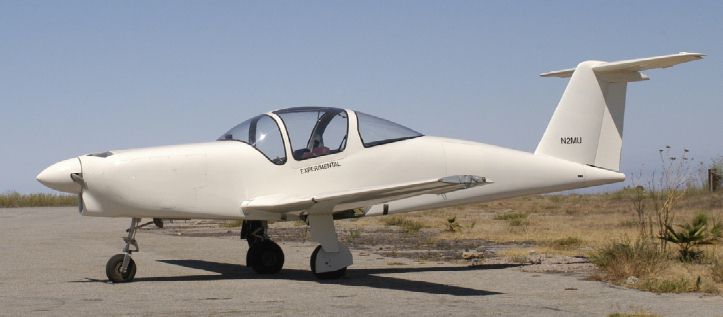
[September 6, 2003]
I've received several kind emails urging me not to lose any sleep over the critical letter from the P-51D replica builder. I appreciate them, but I feel that I ought to clarify that I reproduced that letter (and supplied the ensuing apology) in a spirit of ironic good humor, not of anger or hurt feelings. I don't mind being criticized, particularly when the criticism seems somewhat wrongheaded, and I found the ferocious tone of the letter more amusing than wounding. I knew perfectly well that my getting all that coverage in Flying was due to my editorial position there and not to my homebuilt's being more distinguished than all others. I also knew that some people were bound to resent an honor that they thought undeserved. For the record, the workmanship of Melmoth 2 is, in my opinion, about average for a moderately experienced amateur, and the performance of the airplane is not at all disappointing, but not astonishing either. What is principally noteworthy about it is that it is a fairly successful original design hand-built by a person without any formal engineering or technical training. Those are my laurels, and I am comfortable resting on them.
[September 5, 2003]
I've been away on vacation for a couple of weeks; hence, nothing has been done on the airplane. Just before leaving, however, I did accomplish two things. One was to get the electric fuel tank switching system operating, at least partially. Russ Hardwick, who had made me an electronic timer the purpose of which is to switch fuel tanks every ten minutes or so, decided he could make a better one; and so the timer is not yet installed. But the motor and the pushbutton override are now working, and I can switch tanks by pushing a button rather than by turning a handle. A very small step for mankind, it is true.
Slightly more significant, I figured out why the autopilot misbehaved on the trip to Oshkosh: when I turned it on it would fly straight for a few moments, then begin to bank -- right or left, indifferently -- and continue to bank more and more steeply until I turned it off. When at last I saw what this meant -- it was obvious, of course, once I understood it -- it took only minutes to fix. The wires going to the servo motor were crossed, so that the autopilot responded to a right yaw (it's a single-axis system) with right-turn ailerons. I should have guessed it at the outset; I know I have a gift for wiring things backwards. While fixing that problem, I found that I also had the #1/#2 nav tracker selector switch wired backwards, and the front course/back course selector switch as well. Three for three!
After I returned the mags and harness I had borrowed at Santa Fe, I installed the pair of Bendixes that I had removed from the old airplane around 1980, when I added the turbocharger and found that the unpressurized mags tended to miss at high altitude. For some reason -- maybe just a lucky hit on the timing or something like that, combined with the new Lord mounts -- the engine is now even smoother than before, especially around 2,500 rpm. It's practically like a car -- albeit the noisiest car you could imagine.
Flying recently received the following e-mail response to the issue whose cover was graced by Melmoth 2:
Have
your
journalist lost their minds? What
possessed you to
allow this
aircraft to be showcased in any aspect, much less the feature story.
After
21 years of construction I would be embarrassed to show anyone this
aircraft
much
less
the entire flying community. The
workmanship shown
in the photos
is some of the worst I have ever seen, and the flying specifications
show
the aircraft to be just above a brick with wings. How did he ever get
an
airworthiness cert.
I
am a
Homebuilder currently building a scaled
replica of a
P51 D Mustang
and this article reflects on all homebuilders in aviation, portraying
us as
hacks with no pride in our workmanship.
I expected more from a publication such as yours.
My apologies to all homebuilders whom I have shamed.
[August 13, 2003]
Three items failed during the Oshkosh trip: a heat shield, a part of the turbo mount, and the nose strut retract link, which connects the retraction arm to the strut. The first two I repaired at Oshkosh; the third failure I didn't discover until I was putting the airplane back into its hangar at Whiteman.
The heat shield was a thin stainless steel sheet bolted to the underside of the cowling behind the exhaust stack; its leading edge bent downward and a fatigue crack began to propagate across the part at the bend. Apparently at 175 KIAS there is more energy in the boundary layer an eighth of an inch from the skin than I supposed. I replaced it with a part made of a thicker gauge of steel and with taller downturned flanges along its edges.
The turbo mount part, a longitudinal brace intended to restrain the outboard edge of the turbo against fore-and-aft vibration, failed because in my hurry to get the part installed I did not trim the end of an aluminum spade fitting. It rested on a slightly uneven surface in such a way that tightening the attaching bolt put a bending force across the bolt hole, which proceeded to crack through. This was fixed at Oshkosh by splicing a steel spade into the place of the fractured one. There has been no further trouble with it, and I'm pretty certain that the problem did not have to do with excessive in-flight stresses, but rather with faulty assembly.
The interesting thing to me, however, was the nose strut retracting link, which is also part of the diagonal brace securing the strut in the extended position. This is an aluminum bar one inch high and half an inch wide with spherical bearings at each end, 11.5 inches apart. I had machined the bar into a vertical I section in order to lighten it. The "serifs" of the I are about a tenth of an inch thick, and the web is .07 inch thick. Under some compressive load -- I assume while taxiing on the bumpy grass at Oshkosh -- it suffered what is called a "long column" failure, taking a bowed shape in the horizontal plane. Now that this has happened, it's perfectly obvious why it would. An I-beam like this does not make a good long column, because it has very little stiffness (in technical terms, its moment of inertia is very small) in the plane normal to its web. It's evident that when I designed it I thought only about tensile loads and overcenter locking loads, and not much about compressive loads, which perhaps seemed unlikely to be very large given the 15-degree forward rake of the strut. Or perhaps I realized that there would be significant compressive loads, but did not realize that the part would behave as a long rather than a short column. In any case, I was wrong -- and very lucky that it did not fail completely.
[August 7, 2003]
It took 21.3 hours, 216 gallons of fuel, and two quarts of oil to cover some 3,700 statute miles to Oshkosh and back. I flight-planned 10 gallons an hour, which turned out to be almost exactly right. The turbo wastegate is extremely ineffective, and the 75% critical altitude at the moment seems to be only about 10,000 feet, but the airplane does seem to cruise pretty reliably at 179 knots at 70% of power at a density altitude of 12,000 feet. Taking off at 2,300 pounds or so and climbing at 30/2500 with OATs well above standard, we saw a steady rate of 800 fpm at 110 KIAS up to cruising altitude. Temps stayed well in the green, with all cylinders except #6 (which for some reason is 40 degrees hotter) cruising at about 360 F. The oil still indicates way too hot. The newly-upholstered seats proved to be only moderately comfortable -- my back started to hurt after two or three hours -- and the noise is such as to encourage the use of written notes for communication. The new Lord mounts made a very perceptible difference in the engine vibration, however, taking away its harshness. Despite the summer temperatures and the sketchy ventilation arrangements, the unshaded cockpit was tolerable. Most of the hastily-applied paint stayed on the airplane.
A squall line stopped me at Winslow, Arizona the first afternoon. The next morning a mag failed over Gallup, New Mexico; I continued to Santa Fe, where, with the help of the Jet Center, I borrowed pair of mags and a harness from the state police and managed to make Salina, Kansas by nightfall. My friend Jerry Slocum, recently retired from flying 767s for Delta, had joined me at Santa Fe. We scud-ran into Oshkosh the next morning at 10:00 or so.
The show was fun. The airplane was parked at Flying's tent, and lots of people came by to say "Congratulations!" Some said they had read the whole series of articles since I started writing about the first Melmoth back in the early '70s. A few reported having wept on reading about that airplane's accidental death. I shook hands, autographed magazine covers, answered questions. Pride goeth before a fall, but it feels pretty good in the meantime.
A couple of little things had broken on the way, but got fixed at Oshkosh. We left early Monday afternoon, when an unusually stubborn cloud deck finally rose and cracked enough for the field to call itself VFR. The beautiful Hughes Racer replica took off right behind us; I later learned that it crashed a few hours later in Wyoming, killing its pilot -- a terrible shame in many ways. I dropped Jerry at Albuquerque that evening to catch the last Southwest flight up to Salt Lake, and then I flew up to Santa Fe to visit my mother. On Wednesday I returned to Whiteman.
It was a valuable shakedown trip. Some things went wrong, but most functioned well. There are things that turned up on the trip that I need to fix and modify, and there's still the long list of items waiting to be done, upon which I must now impose some order. Melmoth 2 is far from finished, but -- so far, so good.
[July 28, 2003]
Practically everything is ready. I masked and primed the interior this morning in order to have a coat of UV barrier on the epoxy. Temporary cowl flaps are now in place, simulating the full-open position of the future adjustable flaps. The root cuffs are taped, the gyros back in, the autopilot ostensibly working. The carpets and seats are in place. Hans Kandlbauer, fresh from Zurich in a DC-10 (of which he is the captain), polished the canopy til the acrylic looked black. Tomorrow I'm installing new Lord mounts with the help of a couple of guys at the airport; then a short flight test and, if all is well, departure Wednesday morning for Oshkosh.
[July 21, 2003]
The plane is finally painted. For the past few weeks I've been going to the airport at 5:30 a.m. to paint pieces while the temperature is still moderate; it gets up to 100 in the daytime, and the paint, a marine product called Interlux Toplac, seems to become less manageable. Yesterday Philip Vaughan came to the hangar before dawn (greater love than this no man hath) and we worked for four hours putting one coat of paint on the fuselage and wings. Philip's technique -- he had painted his 37-foot sailboat, which he built in England and sailed over here, four times -- is different from the one I had developed. He brushed the paint vigorously, practically scrubbing it into the surface. With no previous painting experience, I had developed more of a delicate method of "tipping" the paint -- that is, evening it out after spreading it on with a roller -- that resembled a light combing action. My coats came out rather thin, sometimes unacceptably so, with the shadow of the gray primer showing through. Philip got opaque coverage with one coat, but also a few runs. I'm sure they can be sanded and buffed out after the paint dries. The wings look particularly good -- the paint flows out very nicely on level surfaces -- and visitors have been surprised to learn that they were not sprayed.
It will be interesting to see how durable the paint is; I would think that the aeronautical environment would less hard on paint than the marine one, but who knows? At any rate, with departure for Oshkosh just eight days away it's a great relief to have the first coat of paint, at least, behind me. A real paint job can wait until the fairings and wingtips are on the airplane -- and I've won the lottery.
[June 29, 2003]
In the past three weeks M2 has not flown. I spent a lot of time contouring the wing surfaces where I disrupted the finish to add the graphite ply, and prepping other parts of the plane for paint. I've been painting small removable parts, of which there are many. I thought I would get the hang of painting by experimenting on these miscellaneous bits (I'm using boat paint and a brush), but the weather has changed faster than my skill level, and the results have ranged from barely acceptable to lousy. This coming week, with the help of my friend Philip Vaughan, I hope to do at least the upper surfaces of the wings and, perhaps, the lower surface of the fuselage, which I cleansed of oil residue by scrubbing it with acetone and Bon Ami. This has not been the happiest part of building an airplane, by a long shot.
[June 8, 2003]
Just got back from a week in Cambridge, MA, where my son Nick was graduating from college. It is now June, the month in which I promised myself that I would get the plane painted. I still haven't figured out how I'm going to do it. You'd think that someone who could build a whole airplane would know how to lay a couple of coats of paint on it, but no.
I forgot to mention in the previous entry that putting the crankcase vent on the front outlet rather than on the rear one, which sprouts from the filler neck, restored the air-oil separator to its original effectiveness. So that's taken care of; but as soon as one system is working perfectly another one is bound to barf. Indeed, shortly after I installed the Century I wing leveler -- a wonderful little gadget, in my opinion -- the servo quit. Now, this servo had been inop when I first bench-tested it before installing the autopilot, and I had opened it up and cleaned the brushes and commutator; it then worked. Tonight I opened it up again and found that I had dropped a tiny washer into the casing, and it was wedged against the winding. Not a very subtle problem. I fixed it tonight, and hope that the washer didn't do too much damage, and that it will work tomorrow. Because the aileron forces are too high, it's not especially pleasant to hand-fly for long periods when the fuel load is unevenly distributed side-to-side, and the automatic tank switching system, which would take care of that problem, is not yet working.
I made the airplane's first out-of-the-area flight, to Palo Alto (about 300 sm) and back, on May 19. I put in 40 gallons of fuel before leaving Whiteman, and noticed that the weight of the fuel in the first wing to be filled compressed the strut on that side, creating at least the appearance that all the fuel would flow out toward the tip because of the small dihedral angle. Once symmetrically loaded the plane leveled itself, but it did get me thinking about the possible consequences of parking on a slanted ramp.
At takeoff the plane weighed about 2,050 pounds. I cruise-climbed to 10,500 at 120 KIAS. The VOR quickly picked up Gorman, about 40 nm distant, but it seems relatively insensitive; I need to experiment more with antenna placement. On the other hand the comm radio hung on to Whiteman Tower longer than I expected it to. Unfortunately the fuel flow meter gave up the ghost at the start of the flight and so I wasn't able to correlate speed with fuel flow, but it cruised at around 170 KTAS at 27/2500.
It's noisy. Speed stability is not as strong as I'd like; I think that's due to the servo tab on the elevator, which, however, does a nice job of keeping pitch forces in the right range. CHTs are around 370, which is good, except for the front cylinders, which are up around 390. I need to experiment with flow deflectors to get the cooling to even out. (This surprises me, because the lower plenum is so large, but I guess it has dead areas and fast areas nonetheless.) The oil temp still indicates 240, which is too hot by far; that still needs work as well, including recalibration of the sender. On the descent the CHTs drop way down to 200, which is unacceptable. I've designed a new cowl flap system, but it's not built yet.
Approach speed is around 80-85 KIAS, using the Safe Flight angle of attack indicator as a reference. I had to do a series of steep S-turns for spacing on final at Palo Alto, but did not stall and spin. There was a good breeze blowing down the 3000-foot runway, and I was able to turn off at midfield even though the flaps are still up and locked (and will be through Oshkosh).
Before I left for Cambridge I spent a couple of days adding a ply of unidirectional graphite to the wing surfaces above the flap coves. The wing skins are made of a hybrid sandwich, with load-bearing graphite on the inside and glass on the outside. (I didn't have enough graphite for both sides when I first built the wing.) This worked fine for the portions of the wing that are supported by ribs and spars, but the cantilevered rear portion of the upper surface behaved like a bimaterial thermometer, flexing upward and downward with changes in temperature. In warm weather, the upper surface and the flap trailing edge came together neatly; in cold, a 1/4-inch gap opened between them. And I never tried really cold. The idea of the unidirectional graphite, oriented chordwise, is to overcome the effect of the glass, which shrinks and expands quite a bit with temperature changes whereas the graphite hardly changes size at all. It seems to work, though the range of ambient temperatures lately has been pretty narrow. It's the time of year when a stratus layer persists through much of the day, keeping temperatures in Los Angeles steadily in the sixties.
It seems that the airplane is going to be on the cover of the August issue of Flying, and will be featured in the November issue of Popular Science as well, and will be parked in "AeroShell Square" at Oshkosh along with a lot of major aluminum -- honors that, so far at least, it has done little to deserve.
[May 14, 2003]
The effect of increasing the outlet area from 47 to 65 sq. in. was promising; delta-p increased to 5.5 inches at 150 KIAS, and now varies with speed, as you would expect it to. Yesterday I had a look at the cooling outlets on Rutan's Catbird, which also has an updraft-cooled turbocharged 200-hp engine (but a Lycoming); they're just two rectangular holes with rounded rear edges, probably with a total area a bit larger than mine. No one could accuse the Catbird of being an excessively draggy airplane, but I think that some sort of turning vane to guide flow aft as it passes through the outlet would be nice.
In that vein, I'm now thinking about a double-slotted outlet. The problem I face is that the front edge of the exit ramp can't drop down as far as it ought, because the engine's intake manifold is in the way. It might be possible to make a different intake manifold, but that would be a long-term project, and I need to have decent cooling this summer. The area I added on the 12th consisted of a rectangular slot at the aft end of each ramp. It now strikes me that the ramp could float between two slots, like the fore flap on a double-slotted flap, and that by rotating it I could perhaps vary the exit area.
Today we shot air-to-air for the August issue of Flying Magazine. The photographer, George Hall, sat in the baggage compartment of Scaled's Beech Duchess, which Mike Melvill flew. I compared indicated airspeeds with Mike while in formation, and found that at least in the low-cruise range in which we were working, they matched precisely; so I guess I can no longer put off collecting speed-power points.
[May 12, 2003]
Russ Hardwick made up a manometer, and we did a flight today to investigate the cowling pressures. The delta-p (pressure drop) across the engine is constant at about 3.75 inches of water, regardless of speed. This is an unexpected result, to say the least, but it certainly seems consistent with the high oil temperatures and generally mediocre cooling. I increased the exit area by about a third, and will do another test flight tomorrow.
I made a permanent installation of the oil separator on the crankcase breather. Disappointingly, in so doing I deprived it of some of its miraculous properties; I must now check each change I made to see which one is responsible. I have a hunch the problem is due to using a different crankcase vent, and so I plumbed back into the original source today. This will also get tested tomorrow. I've added a wing leveler, a nav antenna and a second comm antenna, all of which seem to be working satisfactorily.
[April 18, 2003]
I have installed a second seat, and under the impulse of inviting some friends up for rides I took a break from continually working on the plane and flew it several times in the past few days. The oil separator in the crankcase breather line, homemade from a design in Sport Aviation, continues to amaze me; not a drop of oil seems to get out of the airplane. I have seldom seen such a small gadget have such a large effect. The landing gear is working nicely too, and there are now gas springs to hold the windows open; the old wooden crutch, veteran of so many engine starts while accidentally left in place, has been retired.
Today I went up to Mojave for the presentation of the White Knight/SpaceShipOne suborbital launch system at Scaled. SS1 is about ugliest aircraft I've ever seen, but it's ingenious. It handles the re-entry problem (from a manageably low initial speed of Mach 3.3, mind you) by flipping up the aft portion of its very low aspect ratio wing and the entire empennage to an improbable angle, so that the whole thing will plummet into the atmosphere almost vertically with tremendous drag and natural stability. The arrangement reminds me of both a dethermalizer on a model glider and a "freewing" airplane that Scaled built a decade or so ago.
As far as Melmoth is concerned, the high oil temperature is more and more of a conundrum, since the cylinder head temps are now on the cold side. I need to recheck the calibration on the sender and also swap out the cooler for another -- I have a spare -- to be sure that there is not some obstruction in it. Today I climbed out of Mojave straight to 10,500 feet at best rate of climb speed and the CHTs did not exceed 400 F. Climb seems to be the airplane's strong suit; even though I have been using a slightly reduced manifold pressure for takeoff and initial climb -- 38 inches rather than 41 -- the VSI pegs at 2,000 fpm. This is in line with calculations, which predict about 2,400 fpm. When I reduce the power to 30/2500 the rate of climb is steady at 1,700 fpm. This is at a weight of around 1,900 pounds, of course; at 2,500 pounds the 2,400 fpm figure would drop to 1,550 fpm, and the 1,700 fpm to 1,150.
[March 20, 2003]
Yesterday I sawed out the portion of the engine air inlet that formed a smooth ramp up to the engine-mount-cum-nosewheel-well. (Look at the picture at the start of "Cooling Flow" to see what I'm referring to.) By so doing I increased the inlet area, measured at the narrowest part of the throat rather than at the leading edge of the lip, by about 25%, to around 60 sq. in. I did this on the theory that the relatively high oil temperatures I'd been seeing (around redline, 230 F), combined with reasonably correct CHTs, suggested that the inlet was too small. If the impedance of the cylinder fins and baffles were lower than that of the oil cooler, the latter would be starved of air flow. Removing the ramp should have no effect on drag, except to the extent that it supplies needed additional cooling air to the engine; air that is not needed for cooling simply bypasses the inlet, whether the internal ramp is there or not.
I made a flight of about 45 minutes today. Climbing to 10,000 feet, I found that the oil temps have come down by about 10 F, but are still not where I would like them to be, namely at 180. The CHTs are actually a little lower than I would like, at around 350 F -- 380 is ideal according to Continental. Maybe I need to close up the cylinder head baffles a bit more.
During this flight I also tested the landing gear free drop. It now works correctly, with the nose strut locking down of its own accord at 100 KIAS thanks to the gas spring.
After landing I found that the temporary reservoir for the oil separator had a couple of ounces of oil in it, but again there was no oil whatever on the belly. The captured oil looked clean to me, and so I am going to relocate the separator to a position from which it will drain back into the crankcase. Another piece of good news from this flight was that true speed seemed to be up by a knot or two, perhaps because the main gear wells are now completely closed. On the other hand indicated speed was down, presumably because of the new, permanent static system. I would have expected that with the pitot tube located at the extreme tip of the wing I would see low, not high indicated speeds, because it would be immersed in an oblique flow field. But all discussion of position error and airspeed calibration is premature until the wingtip extensions have been added. The GPS airspeed calibration (see Links), which is independent of the airplane's ASI, gave 163 KTAS at 10,000 feet at 22 in. Hg and 2,500 rpm -- about 50% of power.
Although most of the news from this flight was good, one piece that wasn't is that my #1 transmitter is practically unreadable from 10 miles out, although it receives fine from much greater distances. Probably an antenna problem; it can wait.
[March 18, 2003]
M2 was ready to fly again at the end of last week when the electrical system suddenly went out. The problem turned out to be a corroded connection at the battery, but I spent a couple of hours replacing the master switch before I found that out. The wind was blowing too hard for test flying on Monday, but today I finally wedged a short flight in between the gales. The gear went down and locked at normal airspeeds, and the (previously uninstalled) main gear doors closed, and the gears locked, on retraction. The turbocharger remained attached, and the oil separator worked unexpectedly well.
The loud noise made by the gear at the end of the retraction cycle turned out not to be under my seat after all; it was a ventriloquistic actuating arm hitting its stop in the nosewheel well. I muted it with a couple of layers of duct tape. It proved relatively easy to get rid of the leaks in the nose hydraulics (there's still one little one in the cylinder itself; I'll get to it one of these days) and the trench in the cabin floor is now filled and glassed over. The carbonised foam core in the cowling floor was impressive -- I've saved it along with a lot of other exhibits for some future museum of bad design -- but it's all been fixed and heat-shielded.
So now I can turn my attention to the cooling issues -- among many other things.
[March 1, 2003]
So, February is gone forever, and still the plane is not back on its wheels. Getting the gear into shape has proved to be a task fraught with deflections and detours. I was able to adjust the positions of the wheels in the wells -- it turned out that the tire size had nothing to do with it; I'm too prone to jump to, and immediately announce, conclusions -- by making very minute shifts (in one case, .025 inch) in the locations of some holes in the retracting arm. The mains were at last going up and locking satisfactorily, and all the doors were closing and looking reasonably flush, but when I plumbed the nose cylinder into the system (running the hydraulic lines through a trench in the foam-cored, half-inch-thick cabin floor) I suddenly began hearing a very loud, alarming Clack! under my seat at the end of the up cycle. I've still not figured out what's making it, but before I track it down I have to deal with no fewer than five hydraulic leaks, including one in the cylinder itself. In the meanwhile I've got the revised turbo support weldment welded up and ready to install, but it has to wait until I've repaired the heat-damaged portion of the cowling floor beneath the turbo and installed a heat shield there. My firm belief that I would be flying again by the beginning of March has proved, like so many other firm beliefs about how long things would take, chimerical.
[February 12, 2003]
I've had the plane up on jacks the past few days, and I found that not only the outboard gear doors were hanging somewhat open (as Mike Melvill had noticed while flying chase) but the inboard ones as well. This was mystifying, since the inboard doors are operated by a series of bellcranks with no lost motion, and so it was very hard to understand how the gear could be up and yet the doors not be fully closed. I inspected the whole system carefully to see if something had gotten loose or shifted. Nothing had. To compound my puzzlement, I found when I installed the middle doors, the semicircular ones attached to the gear forks, that they too were sitting lower than expected.
Then yesterday, in what seemed like an unrelated development, I tried a free drop and found that I could not rotate the mainshaft (which you turn a few degrees with a ratchet to unlock the gear) at all; in fact, I ended up shearing a 1/8" clevis pin while trying to get it to budge. I repaired the manual lowering system (and put in a larger pin), but I still could not figure out what had gone wrong with either it or the door kinematics.
Finally,
however, the light went on. When I first
arrived in Mojave I had some old, cracked tires on the airplane. At
some point I replaced them with a pair of worn but serviceable ones
that a charitable fellow had given me. Well, it seems that the second
set were wider than the first, and were hitting the top of the wheel
well before the retraction system went overcenter to hold the gear up.
What has been holding the gear up all this time is not the overcenter
geometry, but simply trapped hydraulic fluid (as in Cherokees). The
second set of tires were Goodyears, the first McCrearys. I am hoping
that the McCreary is a slightly narrower tire; it's cheaper and
lighter, so I guess it might as well be narrower too. Anyway, I'm
getting a new pair and I'll soon find out. Goodyears won't work; there
just isn't room for them in the wheel wells.
As far as the free drop is concerned, I now understand what was wrong
there too. The bypass valve that you open to allow the gear to
free-drop only short-circuits the pump, not the fluid trapped in the
gear cylinder (or flap or airbrake) by the up/down valve, which is a
center-closed type. You have to put the gear switch down to open the
up/down valve before hydraulic fluid can circulate freely in the gear
actuating cylinder. This is why I encountered such concrete-like
resistance when I tried to lower the gear by hand, and also why I
encountered that same resistance when I was trying manually to get the
nose strut to lock down the first time I cycled the gear in flight. I
think that the reason I never realized this before is that I had tested
the free drop before installing the gear handle in the panel. I used an
external switch and some clip leads to run the hydraulic pump, and set
the valve by hand. I must never have tried to do a free drop with the
up/down valve centered, and therefore closed, and so I had the idea
that if the gear retraction system was not fully overcenter, the gear
would bleed back down. Come to find out, it won't.
It's odd that a machine that I build by hand, and that you would think I, of all people, understand perfectly, can still mystify and surprise me.
[February 7, 2003]
I installed the gas spring in the nose gear. It seems to work nicely, not only applying an authoritative pressure to the retracting link but also damping its motion, so that it arrives gently at the stop rather than slamming against it. I assume that the force holding the gear down is now so great that the hydraulic system will be unable to retract, rather than extend, it; this problem, however, will disappear with the addition of a hydraulic cylinder in the nose gear well.
In the course of inspecting the retraction system, I found that the floor under one of the supports for the torque tube that connects the nose and main gears had begun to delaminate. The failure is identical to the one that occurred under the rudder pedal mounts. There too, the floor began to delaminate because the mounts were bonded to only one side of a foam-cored sandwich. It's obvious to me now that this is not a satisfactory arrangement for reacting concentrated loads; I don't know why it wasn't equally obvious when I built the parts in the first place. The fix involves removing one side of the sandwich, replacing the foam core with a piece of wood, and then bolting some sort of reinforcing angle bracket to the wooden insert before glassing over the exposed side. Mike Melvill told me that the original Defiant had exactly the same problem under its rudder pedals, so at least I don't feel like the only idiot in the world.
I also found, in the course of fixing the turbo support, that the foam sandwich directly below the turbo (and less than two inches away from it) has been cooked. This is structurally inconsequential, since it involves only a small portion of the cowling; but it too will require the same type of repair. In this case, however, the wooden core will provide a support for a metal deflector to keep the exhaust gas away from the outer fuselage skin, and also for an inner heat shield to protect the cowling floor from the turbo.
These are the kinds of modifications the need for which is inevitably revealed by flight experience, and that make nonsense of the idea that an airplane like this should be "complete" when it is presented to the DAR for inspection.
[January 30, 2003]
The airplane having become legal for transponder-assisted flight on Thursday, on Friday I discovered a fatigue failure in the weldment supporting the turbocharger. This required a redesign of the assembly, which I have done, and fabrication of some new parts, which I am doing. At the same time, I am making the new hydraulic cylinder for the nose strut and the mounting hardware for the gas spring. I probably won't be flying again for a week or two.
I have done a temporary installation of the oil separator on the crankcase breather, with a collector reservoir in which I will be able to examine the residue, like a valetudinarian his sputum. One school of thought holds that the separated oil should not be returned to the crankcase because it's full of nasty contaminants; another (to which I belong) holds that the apparent nastiness of the alleged contaminants is due to their being concentrated over a period of time in the collector, in the absence of which they would blow harmlessly overboard as water vapor. I'm not sure whether the present arrangement will shed any light on this question, but at least it will give me an idea of how much oil the separator would keep from coming to rest on the underside of the airplane.
On the credit side, the spectrographic oil analysis revealed nothing out of the ordinary.
[January 23, 2003]
Everything takes so long! Finally today I had the required biennial static/pitot/altimeter/encoder/transponder certification done at Vista Aviation, which is the radio shop at Whiteman and which, by the way, charges the least of several local shops I checked with. Everything went well, and it was instructive to boot. I learned that there is a tiny hole on the bottom of the pitot tube, near the front, and that if you don't cover it you can't test the integrity of your pitot plumbing; that at least some altimeters, if not all, have a baro setting calibrator ingeniously hidden under a little screw next to the adjustment knob; and that if you have a 2000-fpm IVSI you can speed up the altimeter/encoder part of the test by disconnecting it from the static system so that the testing machine can move more quickly from one altitude to the next. I had worried that some glitch would pop up somewhere in the system and cost me either a lot of money or a lot of time; but everything worked fine in the end -- the dinosaur encoder, the ancient Narco AT-50A transponder, the pitot and static plumbing, and the homemade transponder antenna.
In the meantime I changed the oil -- a mess because of the awkward position of the drain plug just above the top of the nosewheel strut. I'll need to make some special tools for that. I sent out a sample for analysis and haven't heard back; I suppose that's good news, since if they find a cam lobe in the sample they call you up, and if they find albumen, you sent it to the wrong place.
My friend Stephan Wilkinson, who built a beautiful Falco but had it professionally painted, later rebuilt a classic 911 for his daughter and painted it himself. He said it wasn't as difficult as he expected it would be. He used a German paint called Glasurit; it costs $580 a gallon. Say again? Is this a case of wandering decimal points, or am I a kind of Rip van Winkel, just emerging into modern realities after a 20-year hibernation with my airplane?
[January 10, 2003]
I'm afraid that I've created an expectation that every week or ten days I'll have something interesting to add to this journal. Unfortunately, I'm no Pepys. But for those wanting to know what the hell is going on...I've installed permanent static ports (with temporary vinyl lines, since my local parts store is out of 3/16 aluminum tubing); the Alcor fuel flow instrument; a delightfully quaint wind-up 8-day clock; and an equally antediluvian Narco AT-50A transponder with an Aero Mechanisms blind encoder that elicited derisive hoots of "Dinosaur!" from my local radio shop. This doesn't sound like much, but I had to remove the entire instrument panel to replace the obsolete King DME rack with the rack for the merely obsolescent transponder. I still have to put in an antenna for the transponder, and then, after a static system test, I can legally fly again.
I've been much preoccupied with the question of painting. I'm not very perfectionistic, but I'd like the plane to look good from twenty or thirty feet away. Cory Bird, who has the most perfectly painted airplane I've ever seen -- a homebuilt, obviously -- came down to Whiteman with Mike Melvill last week, and over lunch described his technique. It sounded like the kind of thing I am simply incapable of. On further reflection, however, I realized that about half the airplane can be easily removed, fine sanded by me (the filling, smoothing, and priming have already been done by the talented Roy Bailets) and trucked to the local Earl Scheib equivalent, where some artful fellow with a hot hand will spray them at small cost. That will leave only the fuselage and empennage for me to ruin.
[December 31, 2002]
When I landed at Whiteman on December 23 the tower controller asked me to cycle my transponder; "I'm negative transponder," I replied, forgetting that I was thereby confessing to an infraction, Whiteman being within 30 nm of a Class B airport. The controller was apparently in a tolerant mood, because he didn't complain; but maybe I'll get a certified letter one of these days. Once I was reminded that I had to have a Mode C transponder to be where I was, that moved up to the top of the to-do list. Now the first few items (out of about 50) are:
transponder/encoder
change oil and filter
wash
swing compass
fuel flow/totalizer
nose gear cylinder and spring
overhaul Dukes pump
oil separator
...
and so on and so on. Paint has also moved up from the very end of the list, because it seems that Melmoth 2 will be going to Oshkosh and will need to be presentable. I have my fingers crossed that the transponder and encoder still work; several items of electronic equipment so far have failed, apparently as a result of their 20-year rest in a cool dry place.
Mike Melvill kindly lent me an Alcor digital fuel flow instrument to replace my Silver Instruments totalizer, which was one of those casualties of Time. Today I spent several hours installing it, as well as a clock, in the space vacated by the rather large, antediluvian Silver device. (It's amazing how long these simple tasks take; I didn't finish.) On Thursday (Wednesday being consecrated, I suppose, to social rites associated with the new year) I'll have to pull the instrument panel -- always a daunting task -- in order to make a notch in its bottom edge to accommodate the transponder, which I am mounting where I had originally planned to mount the now obsolete, but half an inch thinner, DME. I'll paint it while it's out. Decisions, decisions: grey or black?
The engine has been blowing out a lot of oil, but since all cylinders have very high compression I'm inclined to attribute that to factors other than blowby. Ray Henning gave me a neat little separator that I'll install on the rear baffle -- it's extremely light -- and drain back into the engine. I hope it will reduce the amount of crud on the belly.
I revisited the question of static port location, repeating the CFD procedure on the computer, this time more precisely than before, and arriving at essentially the same answer. What I'm looking for is a place that fulfills two different requirements: first, the local pressure must be as close as possible to static, and second, the local pressure must vary as little as possible over a wide range of angles of attack. Here's what the pressure distribution over the airplane looks like when painted with a very narrow spectrum width -- that is, any area with a pressure coefficient (Cp) of +0.01 or higher is blue, and any area with a Cp of -0.01 or less is magenta. (A more typically useful range might be from -0.4 to +0.4.) Green represents a Cp of zero. The effect of adjusting the color spectrum this way is to isolate the areas of near-zero Cp very distinctly.
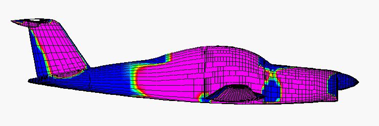
It's remarkable, and fortuitous, that the green vertical band of zero pressure difference on the aft fuselage only moves forward or aft an inch or so over a range of angles of attack from -2 to 10 degrees. The region near the leading edge of the windshield, which would otherwise be preferable because of its proximity to the instrument panel, is much less stable.
[December 23, 2002]
After a couple of comical missteps, M2 is back in its own hangar, the 25 hours of Phase One flight testing having been completed. Now it's a real airplane, and could leave for Paris in the morning but for a few details. The speed envelope has been opened from 62 to 190 KIAS; my intention is to demonstrate freedom from flutter up to 200 KIAS and to make 180 KIAS the never-exceed speed, but prior to the final step I'll calibrate the airspeed indicator so that all speed-related information will be consistent.
The last few days have been occupied with efforts to improve the effectiveness of the brakes. I did some fiddling with the pedal geometry that helped a bit, but then Mike Melvill, who has done almost half of the initial 25 hours of test flying, had a complete failure of the left brake. Not having O-rings suitable for overhauling the brake, he decided to perform a further modification that we had discussed: he replaced the brake master cylinders with others having a smaller piston diameter and therefore presumably higher mechanical advantage. This was quite a job; he machined several new mounting components and revised the pedal geometry while I was baking Christmas cookies in LA. (The world needs more people like Mike Melvill, and fewer of a number of other sorts.) He finally installed the new cylinders and found that they felt nice and firm.
Shortly before midnight last night, however, I found an e-mail from him. Its tone was despondent. The brakes did not work at all, and he could not find the reason why. I left early this morning for Mojave to see if I could help figure out the problem. It took til Rosamond, about 13 miles short of Mojave, for the light to go on. The parking brake must have been inadvertently set! Indeed it had, and Mike had not realized it because my preflight briefing to him had omitted the parking brake; it's in an out-of-the-way location and I never use it. He had no idea there even was one in the airplane. That mystery solved, we bled the brakes again and I made a couple of circuits and full-stop landings. The brakes are wonderful -- a huge improvement.
In the middle of the afternoon my son Nick, for whom this plane was originally begun, and his friend Jared Noble arrived at Mojave with a pickup to lug all the junk I had accumulated there, and the car in which I had come up, back down to Whiteman. I took off around 3:00 and arrived at Whiteman at 3:20. Sure beats driving.
[December 12, 2002]
Almost immediately after I wrote the foregoing (see below), I received an e-mail from one Jay Epting referring me to http://www.ntps.com/downloads.htm. There I found various stuff on GPS airspeed calibration, including an online spreadsheet that does all the math for you.
The gist of it is that after noting down the altitude and OAT you trim your airplane for some indicated airspeed and fly four different headings. I flew headings 90 degrees apart, but I think they could just as well be 80 or 70 degrees apart. You record the GPS groundspeed and the heading for each leg. Legs are very short -- just long enough to get a stable speed, which takes no time at all. You do this for as many speeds as you like, from just above the stall up to Vh. You then go to the spreadsheet and enter the data. As soon as you've entered it (actually, you only need to enter three legs, but four improve the accuracy a bit) your true airspeed pops up, together with the wind speed and direction and the standard deviation of your data, which is a measure of the internal consistency of your groups of points. Errors can creep in because of changes in the wind speed or direction or failure to wait for a really stable airspeed, but if you pick a day when the air feels smooth they probably won't amount to much.
Now you go back and figure out the true airspeeds corresponding to each of your indicated airspeeds (that's why you need the altitude and OAT), and subtract them from the calculated true airspeeds. The differences, plotted against airspeed, give you a calibration curve. My airspeed system turned out to be way out of kilter, with errors of between +4 and +7 knots between 80 and 150 KIAS, the smallest error occurring at 100 KIAS. The error is increasing rapidly at the low end, which suggests that the indicated stalling speed of 68 knots really means something more like 60 knots -- more in line with what you would expect. It's not too surprising that the system isn't accurate, since the pitot tube is out at the wingtip and is immersed in some weird spiraling flow. Until I add the planned wingtip extensions, moving the tip flow away from the pitot, I don't expect much accuracy from the system.
One of the articles I found on the Web -- the incredible, ever-helpful Web -- suggested an alternate method that does not require the solution of three or four vector equations in three unknowns (which is what the spreadsheet genie is doing for you). First you determine the wind direction by flying a circle at standard rate while watching the GPS groundspeed. The maximum and minimum occur when you are flying directly down- and upwind, and so define the wind axis. The wind speed is half the difference between them. Once you know the wind speed and direction, you can do your groundspeed runs along the wind axis and simply add or subtract the wind speed to get your true airspeed. I tried this method along with the other and found the results to differ by two or three knots, perhaps because the maximum and minimum groundspeeds each persist for about 30 degrees of your circle and make a precise determination of the wind axis difficult. Actually, I don't know which results were more accurate, but I would think the spreadsheet approach would be because each data group contains its own snapshot of the wind at the time it was done and averages a number of results.
We have now flown 14.1 hours out of the required 25.
[December 9, 2002]
Mike Melvill, my nominee for Greatest Man in the World, put several more hours on the airplane over the weekend while I was away in Death Valley. It's now approaching 11 hours. He has opened the envelope from the stall to 170 KIAS, a task that would have taken me a month and several prescriptions for sedatives. He also collected a good deal of speed-power data, but in the absence of an ASI calibration it's not yet possible to know what it means.
My previous description (see below) of calibrating airspeed with the GPS was in error; merely averaging airspeeds on two reciprocal courses works only if you happen to be flying directly up- or downwind, and of course that's something that's impossible to know. There is a way to do it, however, that I believe was described in Sport Aviation a few months ago. I need to find it.
The stall is without any warning to speak of, dropping one wing or the other depending on the positions of the rudder and ailerons, but it is not violent. It progresses outboard from the root, despite the wing's fairly severe taper in both chord and thickness; so it appears that John Roncz's airfoils and twist distribution are working as hoped. So far, so good. This is fun.
[December 4, 2002]
This morning Mike Melvill flew the Scaled Duchess with the baggage door off and Cory Bird shot 76 air-to-air pictures of M2 using a Nikon digital camera and a 3008x2000x16M pixel format. They're beautiful. Late in the day, long after I had driven back to LA, Mike flew M2 while holding in one hand a sheet of instructions I'd made for him the night before. Everything worked fine. He opened the envelope to a minimum speed of 67 KIAS -- still not stalled -- and a maximum of 140 KIAS. That "maximum" merely means the maximum speed at which the stick has been whacked to try to get the empennage to flutter, a nerve-racking activity that falls in the "tickling the dragon's tail" category, since fully-developed flutter could take the empennage right off the airplane. No sense yet of the airplane's speed capability; the power setting to achieve 140 KIAS is still very low, and of course the ASI is not yet calibrated (though it matches that of the Duchess within a knot at 105 KIAS).
I didn't know Mike would fly the plane today (though I had invited him to fly it) and when I came home and found the phone message that he had I felt extremely tickled -- I'm not sure why.
[December 2, 2002]
That "tomorrow" on November 19 was optimistic. Actually, I spent most of a week trying to get a decent seal between the engine, the oil diverter plate, and the oil cooler. I finally got it right on Saturday, 11/30. Today was the first long (well, an hour) flight without any problems to force me to go back and land.
Weighing no more than 1,750 pounds, M2 climbed rapidly to 10,000 feet, despite my running at rather low power -- 28/2500 -- to keep the cylinder head temps down. I tested the ability to raise a wing with rudder, which was positive (that's good) and got a calibration of sorts on the Safe Flight angle of attack indicator. Lateral stability seems okay -- just about neutral with up to 20 degrees of bank. Speed stability is good, and M2 has the same pleasant landing characteristic that M1 had. I have yet to make a bad landing; it practically flares itself because the wing enters ground effect before the stabilizer does.
The batteries in my handheld GPS died before I could do much of a speed calibration. The only point I got was 120 KIAS at 10,300 ft., OAT zero C, with a lean mixture and a power setting of 19/2300 (so low that it's off the engine power chart, but I'd expect that about 33% power would be required for 120 KIAS at this weight). GPS groundspeeds up- and downwind were 143 mph and 164 mph, for an average of 133.5 kt. These figures are not especially consistent; 120 KIAS should be 141 KTAS. The point of the exercise is to determine whether the static location, currently on the tailcone, is any good. A more efficient way to do this is to formate with an airplane that has a calibrated airspeed indicator; but after all, you've got to do something up there to kill time.
The project for the coming hours is mainly to expand the flight envelope upward toward the cruising speed range and downward to the stall break. With some speed-power points in the charted range of engine settings, I should be able to start getting a handle on the parasite drag coefficient -- the single most important number for this airplane.
[November 19, 2002]
The oil temperature problem is finally solved. The plumbing of the lines running to the airframe-mounted oil filter was crossed in a way that was not apparent even to the eye of a person looking for that very problem. Since oil filters contain a check valve to prevent reverse flow, which would collapse the paper filter element, and since the filter and cooler are in series on my engine, the effect of crossing the lines was to prevent any oil from flowing through either the cooler or the filter. The oil temperature now holds steady at the expected 80 C, and the cylinder head temperatures have come down by about 30 C as well. Tomorrow I can at last start building time and experience in earnest.
[November 14, 2002]
The oil temperature continues to be a problem, though it is at least beginning to feel comfortably familiar. Since even when the oil temperature has risen very high in flight the cooler and filter are merely warm to the touch after landing, it's apparent that no oil is flowing through them. That can be due to a faulty vernatherm valve, obstructed cooler, or some obstruction in the lines running from the engine to the airframe-mounted filter. I have swapped vernatherms and tested both, and they both seem to be working normally. Next I will swap oil coolers and check the lines for obstructions.
Today I raised the landing gear, and then spent a tense quarter-hour trying to get it to lock back down. I had anticipated that aerodynamic drag would limit the speed at which the gear lowering cylinder would be able to drive the nosewheel, which swings forward, to a locked position. I underestimated the effect of propwash, however, and not until I slowed to 80 KIAS and reduced power to idle was I finally able to get the gear to lock down. On returning to land, with the oil temperature slowly retreating from its peak of about 300 deg. F (redline for this engine is 240), I was greeted by fire and rescue trucks; it turned out that the tower had been listening to my conversation with Mike Melvill, who was flying chase in his Long-EZ. All's well that ends well, however, and Mike managed to snap a few photos of the plane in a cleaned-up state. Here's one:
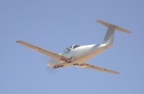
Not surprisingly, Melmoth 2 feels quite a bit cleaner with the gear up. Until I get the oil temperature problem fixed, however, it will be impossible to get any sense of its performance. A few minutes after we landed Dick Rutan appeared and informed me that upon realizing that the gear would not lock down I had uttered an impermissible expletive upon the frequency. My apologies to the FCC.
[November 7, 2002]
Having spent the first three days of this week checking and fixing various stuff, I hoped that when I flew this morning I would find that the overheating problems had vanished. No such luck. I had discovered on Wednesday, while attempting to calibrate the induction air temperature probe with boiling water, that the toggle switch that selects oil temperature or IAT was mislabeled. The outrageous 125 deg. C temperature really belonged to the oil -- where it was a bit past redline, but at least imaginable -- and the 90 degree reading belonged to the air, where it was awfully high, but not inconceivable. In any case, however, the oil temperature went up there again today, and so I landed, again, after less than ten minutes in the air.
Perhaps the problem is a sticking vernatherm, the valve that allows oil to go through the oil cooler once it has gotten warm enough. I'll look at that on Monday. In the meantime, I'm remaking a piece of the trim tab control system in order to provide myself with more nose-up trim -- the lowest speed I can trim to now is about 110 KIAS -- and scrounging for a vacuum pump, the drive shaft of mine having sheared during the first flight. This test-flying business is starting to look complicated.
[November 1, 2002]
This morning I woke up at four and couldn't go back to sleep, thinking about the impending first "up and away" flight. I went running in the nearby park under a sliver of waning moon, and left for Mojave at 6:00. Mike Melvill had left a crash helmet and a parachute -- a nicer one than mine -- on the wing. Later, as we briefed for the flight, which he would chase in Scaled's Beech Duchess with Cory Bird shooting video from the back and Mark Mangelsdorf taking data, we discussed how it would be to bail out of an airplane. We had both made deliberate jumps, but never emergency ones. Mike, who has made many first flights as a test pilot for Scaled and is the world's leading authority on the Long-EZ, was of the opinion, to which I had come as well, that if, say, the plane were on fire and you were bailing out under control, you could do it, but that it would be unlikely that you could extricate yourself from a tumbling airplane if some major piece fell off. Such are the cheerful thoughts that wake you at four a.m. before a first flight.
The wind was calm, OAT 60 degrees. Mike took off from 30 while I held in position. As he came around from behind and gave me a signal, I pushed the throttle forward, as per the instructions written beside it. I rotated at 70 knots, reduced power to 32/2500, and accelerated to 120 KIAS in the climb.
By the time I freed my eyes from the horizon to scan the panel, some of the CHTs were already looking high. I limited power to about 28/2500 and rate of climb to 200 fpm with the gear left down. We made a wide pattern, remaining near the airport. The CHTs stabilized, two cylinders near the top of the green, and then a new problem appeared: the oil pressure was dropping. After about 10 minutes airborne it had fallen below 10 psi, and so I returned and landed.
The induction air temperature, measured at the back end of the log manifold, had been running at 125 C -- a pretty astonishing level -- but the oil temp was an unremarkable 90 C. Examining the engine on the ground, we could find no immediate explanation for the oil pressure problem -- on a subsequent start it kicked right up to 80 psi, as expected, so it wasn't a pump failure -- or for an abnormally large rpm drop on the left mag. Compressions are good -- all 75-79/80 -- and the plugs look normal. No sign of excessive oil loss from the breather.
On Monday I'll start working on the various problems in a systematic way. The map of possible causes, and possible solutions, is complex. But the world is full of Continental TSIO-360-Fs that are running just fine, and so I know the answers will turn up soon. The world is not full of Melmoth 2's, and so, though it was disappointing not to be able to remain airborne longer, the happy side of the flight is that the airplane handles very well, is stable and easy to fly, and is not out of rig; in short, its problems are not aerodynamic. With autumn temperatures dropping at Mojave it should be possible to continue to debug the cooling in flight -- the long delay in getting licensed may, ironically, turn out to have been a blessing in disguise.
Cory's videotape of the plane in flight is beautiful. I'm really looking forward to seeing the airplane with its gear up. First, however, the oil pressure has to stay put. Here are some frames from the video; I'll have better-quality stills in the future.
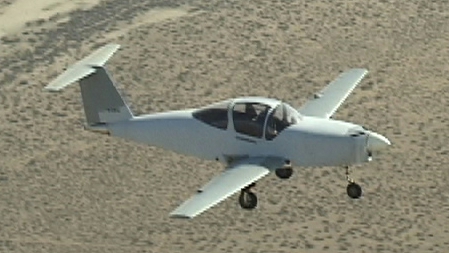
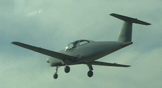
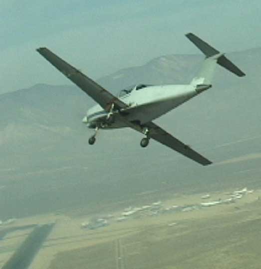
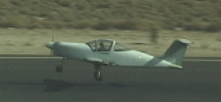
[October 31, 2002]
This morning it was calm -- just a breath of wind from the east, of all places -- and I made three runway flights on Runway 30, which is 9,600 feet long. I suppose I was airborne for about 15 or 20 seconds on each flight. The plane felt very solid and stable, and heavier than it really is because I had too much nose-down trim and my hands were too securely glued to the sidestick and throttle to adjust the trimwheel in flight.
There is a curious moment of transition as the wheels leave the ground. You're looking for the combination of speed and deck angle at which lift equals weight, and suddenly you've got it, the texture of the runway surface under the wheels vanishes, the plane gives a little sashay and then settles down perfectly steady and solid, and the crisis is past, you're flying, and all anxiety -- well, almost all -- is gone.
So that milestone, which loomed so large before, now recedes into the distance behind me. I'm planning to do an "up and away" flight tomorrow, weather permitting. In other hot news, I picked up my repairman's license today. "Now," the FAA guy said, "you can work on it."
[October 30, 2002]
For the last two days, the winds at Mojave have refused to cooperate. On Tuesday it was fairly calm in the morning, and I busied myself with a few finishing touches. At one o'clock, just as I prepared to taxi out, the wind kicked up with amazing suddenness. As I was taxiing, Mike Melvill was landing in his Long-EZ. Through the tower he relayed to me his advice not to get airborne under any circumstances; the turbulence was terrible. I had already realized that I wasn't going to fly that day. I made a fast taxi down Runway 26 -- the long runway, 30/12 would be necessary for a runway flight -- in order to determine the manifold pressure at full power. It was 35 in Hg. On returning to the hangar I adjusted the wastegate to bring it up a bit -- it should be 40 -- and then headed back to LA. That night, the wind hit 75 knots in Mojave, tearing a steel rollup door from one of the Scaled Composites buildings.
This morning, Mike sent an e-mail saying that the winds were calm and that I should hurry up to Mojave. After dropping my daughter at school I headed north. The wind was calm as I passed through Palmdale, but by the time I reached Rosamond the creosote bushes were bending before it and the windmills on the foothills to the west were spinning merrily. Arriving at the airport at nine, I found the hangar floor covered by a uniform layer of fine dust about an eighth of an inch deep -- the result, I understand, of an ill-advised decision of the airport operators to remove every trace of vegetation from the airport grounds.
I rolled the plane out immediately, but again by the time I reached the runway it was blowing 25 knots from 250 degrees. Since a runway flight is a fairly delicate maneuver, requiring precise handing of an airplane with whose responses one is not yet familiar, a gusty quartering crosswind is not recommended. I held for the landing of a SAAB Draken, a beautiful narrow-delta airplane that deployed a parachute during its rollout. Again, I did a fast taxi to check the MP, and, finding it still too low, returned to the hangar to adjust the wastegate again. Later in the morning I made another fast taxi, this time up to 90 KIAS, showing, if nothing else, that the nosewheel is free of shimmy. But still no flight. I'll go out again tomorrow if it looks promising; if not, I'll try Friday -- Lily has the day off from school to recover from the exertions of Halloween -- leaving home before dawn to catch the morning calm at Mojave.
Although this seems like a story of pure frustration, it's actually more complex that that. There are many anxieties associated with the testing of a new airplane, and they incarnate themselves in the noises and vibrations and jolts that you experience while taxiing, accelerating, and braking. At first, I worried that the landing gear would collapse as I rounded a corner, or that the engine would catch fire or the turbocharger would melt the composite air box. More generally, I experienced a kind of diffuse anxiety that felt like stage fright, or like the emotions I used to have when I was an amateur parachutist and the jump plane was carrying me up to altitude. More important than the rational recognition, from repeated outings on the runways, that the various parts of the airplane are behaving as they were designed to do, is the simple familiarity that comes from repeated starts, taxis, accelerations, and shut-downs. So when I finally do get into the air, at least part of my anxiety will have been carried off by the sheer repetition of the preparatory steps.
[October 28, 2002]
Finally, the airplane has a certificate of airworthiness. Tomorrow, with any luck, the runway flights begin.
[October 16, 2002]
Last Wednesday the inspector from Scaled Composites, Rick Aldrich, came back for another look and this time declared everything compliant and flightworthy (as far as he could tell). I called the FAA inspector the next day and left a message that I could be at Mojave any time he liked, even at 90 minutes' notice. But he hasn't had time to return my call yet.
[September 29, 2002]
An inspector from Scaled Composites came to look my airplane over. He did a very thorough job and found a bunch of discrepancies, all minor. I took care of most of them last week, and will get the rest early next week. The most time-consuming items are labeling everything in the cockpit -- even though I designed and built the throttle, I have to put a label on it saying "Throttle", and so on -- and making the snarl of wiring behind the panel, much of it provisional, look as though it had been created by a human, not a rat. When I finish these things up, he will come by again, and if he likes what he sees he'll call the FSDO man to discuss it. Then maybe something good will happen for a change.
On Thursday, Dick Rutan hobbled up on crutches, his left foot badly damaged in a dirt biking accident. He told me a good story about the time the entire propeller flew off his LongEZ as he flew at 11,000 feet above a fog layer that extended from horizon to horizon. He looked over my engine installation and, after a polite hesitation, advised me to move some oil plumbing farther from my turbocharger and to install additional heat shielding around the exhaust pipes where they enter the turbo. He was kind enough to provide some soft, corrugated stainless steel sheet for this purpose. I'll take his advice.
The funny, and psychologically revealing, part of Dick's prop story was that the departure of the prop had been preceded by increasing vibration, and he had throttled the engine down to an idle. When the prop left -- he happened to look back over his right shoulder just in time to see it go cartwheeling away -- the vibration ceased, and his first reaction (so deep is the denial into which a potentially fatal emergency puts even an extremely experienced ex-fighter pilot) was to think, "Okay, that's fixed," and push the throttle forward.
[September 14, 2002]
I installed one of my comm radios, which had been repaired by the manufacturer after various massive failures apparently due to age. It failed again by the time I had taxied halfway to the approach end of Runway 30. I shipped it back, and installed the other in the second rack. This one worked fine; so now I can move about the airport freely. At this point I have spent more money having two comm radios repaired than I did on dual comms and navs, audio panel and glideslope, professionally installed, in 1975. On September 12 I did some more taxi tests, mainly to check the radio and to verify that I could raise the nosewheel off the ground. I could, at about 45 knots.
The weather at Mojave is milder now, with temperatures in the 90s and calm or light winds. Soon it will be fall. I continue to take pleasure in the drive over the Angeles Forest Highway, where I seldom see another car and the air is crisp and clear. The drive helps to dissipate the irritation of being grounded by quibbles. The mountains, like the shoulders of indifferent giants, remind me that The Roman and his troubles now / Are ashes under Uricon.
A couple of interesting Mojave sightings: one, an Antonov 124, a four-engine transport, brought here to join the hundreds of other airline and cargo aircraft in storage awaiting a fresh rebirth of the world economy. The Antonov is an attractive airplane with vast number of wheels, marked anhedral, and a fat, shapely fuselage. Its exotic looks are marred only by a prosaic empennage. Far weirder is the latest Rutan project, which is a mother ship for launching thrill-seeking hyperconsumers on brief suborbital rides in rocket planes. It has a wing of what appears to be about 80-foot span. Two long booms are mounted about twenty feet apart; each has its own separate T-empennage and a long forward projection, sloping downward like the nose of an anteater, at the tip of which is a nosewheel. The cockpit is in a central pod, high above the ground, with two jet engines on pylons in a V shape, like those of Proteus, at its aft end. The rocket plane will be slung beneath the central pod. This airplane, whose name I don't know, has already made several flights.
I asked Mike Grimes (the DAR whom I had contacted about inspecting my plane during a period of several weeks when the FAA inspector was too busy to come by) for chapter and verse on the requirement that if a component is installed on the airplane, it must be functional (see the September 3 entry below). He referred me to 8130.2D (the FAA document governing certification, including that of amateur-built aircraft), 127(a)(1)(b): "The FAA [must find] that the aircraft complies with acceptable aeronautical standards and practices." I am heartened to see that this requirement leaves some latitude for interpretation. I had supposed until then that Grimes's insistence was based on 127(e)(7)(a): "The aircraft should be complete in every respect." I had called the Washington press office for an interpretation of the latter phrase, which makes very little sense when applied to a unique experimental prototype. They checked with the Washington FSDO (I assume), who said, "If it is safe and meets minimum equipment and paperwork requirements then it qualifies for Phase 1 approval. This is all we're allowed to look for."
[September 3, 2002]
Okay, so where are we now?
Well, I spent a week and a half's vacation on the east coast trying, only half successfully, not to think about the plane. Before going, I started an exchange of e-mails with a DAR, Mike Grimes, who I had hoped might be able to look over the airplane before the end of the month. As it turned out, he couldn't, but I learned from him that if a component is installed on the airplane, it has to work for him to sign it off. In other words, the fact that my airplane has flaps, but the hydraulics to operate them are not yet installed, is automatically disqualifying. He also mentioned seats; if there were "mounts" for four seats, four seats had to be installed. It is not clear to me if this applies to radios as well; if there are racks for six radios, do all six have to be in place and working?
This seems to me to be a rule that ought logically to apply to kit-built airplanes, when it is assumed that the builder is not himself engineering the airplane and is not qualified to decide how things ought to be done. I don't see the point of applying it to one-of-a-kind airplanes designed by the builder. But I understand that a designated inspector has to abide by the rules, and if that's the way the rule is written, that's the end of it as far as he is concerned.
My own thinking about the flaps is that if the airplane is safe to operate at its design gross weight of 2,850 pounds with the flaps, then it is equally safe to operate at 2,000 pounds without them. The lift increment to be expected from flaps is about equal to the weight difference, and so the approach and landing speeds would be the same. Braking effectiveness, of course, is greater at the lower weight. In any case, however, the inspection criterion is not landing speed, but "completeness." If the airplane had no flaps, there would be no objection, regardless of its weight; but since it has them, they have to work.
My desire was to fly the airplane, get a sense of its handling qualities, and correct any discrepancies before going on to add complexity to it. Now I have pretty much resigned myself to having to defuel and dismantle the airplane and trailer it back to Whiteman; the four months it has spent at Mojave would be little more than lost time. But I still cling to a faint hope that the FAA inspector will interpret "completeness" more generously, and sign the airplane off to fly at its present weight and with its present equipment. It is, after all, a complete airplane; it just isn't yet the airplane it's intended to be. When the flaps are functional, I would get another restricted test period of five hours.
Of all the surprising aspects of the months I have spent trying to get the plane licensed, the one that surprises me most is that no one ever said to me, until now, that all installed components had to be functional. There is no statement to that effect in the FAA advisory circular on the certification of homebuilt airplanes -- only the word "complete," which has turned out to be a Trojan Horse and a Pandora's Box rolled into one.
[August 9, 2002]
The oil pump drive gear passed the torque test.
I sent copies of the engine and prop log pages to the FAA inspector, but he wants to look at the airplane again and is not available until after the 28th. In the meantime I have been going over eveything with a fine-toothed comb. The Cherokee that I was using to commute to Mojave went into the shop at the end of June because of a landing gear problem; it was a month before it came out, and then it was sold. In the meantime, I've been driving back and forth to Mojave, usually over the Angeles Forest Highway, which is quite beautiful. I've done the 180-mile round trip so often now that it seems short.
[August 3, 2002]
The prop is back on, smoothed and repainted and fresh as new. The overhaul cost a fortune -- almost four times what I paid for the propeller in 1972. About a quarter of the cost was due to the dome having been scarred on its outer surface by friction with the front spinner bulkhead. The surface damage in no way affected the serviceability of the part, in my opinion at least, but to comply with the letter of the law it still had to be replaced. Hartzell gets a cool $516 for this simple aluminum cup. Also in the category of pointless expenses, the attachment studs had to be replaced because the ones I had were for a 520 engine, not a 360. The 360 studs are about a quarter-inch shorter; there's no functional difference, and the 520 studs had worked perfectly well for 2,000 hours on Melmoth 1. But those are the rules.
To avoid a repetition of the dome disaster, I remachined the front bulkhead to increase its clearance and inserted a larger, harder O-ring between it and the dome. Henceforth, I'll remove the spinner at intervals to check the condition of the O-ring; I don't think it had been off the prop in the past 24 years. To be fair, though, I shouldn't grouse too much. The prop had gone 24 years without even being inspected, and so I guess it was time. The AD process is a rational one; if it didn't exist, we'd wonder why not.
On to the engine. Traveling backward in time, it slalomed safety though a thicket of ADs before finally colliding with a 1981 notice requiring that I have the torque checked on a nut securing the oil pump drive gear. This will be accomplished on Monday. It seems that if the nut doesn't clamp the gear tightly enough, the gear, which is locked with a Woodruff key, wobbles, and can eventually crack at the keyway. If the nut fails the test, the accessory case has to come off and the oil pump drive gear has to be replaced; but if I get lucky, I can take my logs and other paperwork to the FAA on Tuesday and maybe finally get signed off.
In the meantime, I heard from S-Tec that it will cost a bit above $1,000 to make my MicroLine radios serviceable again.
[July 24, 2002]
With the help of Ray Henning and Dick Eklund, I pulled the prop and took it to Executive Propeller at Van Nuys on Wednesday of last week. I learned on Thursday that it needed to be overhauled. At this rate, I'm not sure I can really afford to own an airplane, but I'm keeping my fingers crossed that after this I'll get lucky. I found out at the same time that my friend and engine maven Mike Attolico has moved his business, Western Cylinder Overhaul, from Van Nuys to Whiteman, just a little way from my hangar. He's looking into the engine ADs and service bulletins, if any. No news from that quarter yet; so I spent the first part of the week on a beach in Ventura with a bunch of pubescent girls. (Not so lurid as it sounds.)
On my return I found that 1) XCOR has announced that it is going into the suborbital flight business; and 2) three exposed threads are an old standard of aircraft assembly practice to ensure that, on the one hand, the nut is cinched on the material being joined, not the bolt shank where the threads end; and, on the other hand, that the parts being joined are bearing on the bolt shank and not on the threads. Given the wide variety of nuts now available and the wide variety of types and applications of joints, the three-threads rule can hardly be considered absolute; but it is applied as if it were. In the course of checking this out I also learned the interesting fact that 90% of the tensile load on a bolt is borne by the first three engaged threads.
The prop is supposed to be ready tomorrow. If I can get it early enough, I'll put it back on the airplane.
[July 13, 2002]
On Wednesday evening I heard from the FSDO guys that they would come by the hangar on Thursday or Friday.
On Thursday I drove out to MHV with a set of jacks in the trunk. I borrowed 650 pounds of steel shot bags from Scaled (they use steel now rather than lead because if a bag breaks you can collect the debris with a magnet). I put a jack under the tail and sawhorses under the wings, and loaded the horizontal tail as planned. Nothing broke.
I removed the inspection covers and cowling. I disconnected the nosewheel retraction linkage, jacked the mains, and attempted to cycle the gear. Nothing happened. I later found the problem in an improperly adjusted microswitch, and successfully cycled the mains. The new tires fit into the wells -- not surprisingly -- but this excess-of-caution test did have the virtue of revealing the microswitch problem. I am thinking that it would be a good idea to add an extra pushbutton to energize the hydraulic pump even if the normal circuitry, which is triggered by movement of the panel lever, fails to operate.
While I waited for the FAA, Dick Rutan came by to invite me to watch a flight of the XCOR EZ-Rocket, the rocket-powered LongEZ that is being used to test some prototype rocket engines. I went down to the 26/30 intersection. A dark cloud hung high above the airport, and scattered drops of rain fell on the hot ground. I could see the flash as the engines lit off. The first takeoff looked pretty much like that of any LongEZ, but the rocket burns 450 pounds of fuel in two minutes. Dick would climb steeply, turn off the motors, glide back to the approach end, relight, and climb out again. By the second relight, the climb was thrilling to watch, with the white flame of the rockets visible against the dark sky. The noise is very loud, a rumbling, crackling, billowing, uneven sound like that of old turbojet fighters. It's just the right sound for the swept-wing EZ; the putt-putt of a Lycoming has always seemed to me incongruous in association with that shape.
I'm curious about the intended use of these engines. Do they have something to do with the multi-million-dollar "X Prize" for the first launch of passengers into space by a private organization? XCOR, X Prize -- do we detect a link? Or does everything have an X in it these days? I can't help suspecting that Burt Rutan would want to make space flight his crowning achievement. Everybody denies everything, but I still wonder...
The FSDO guys, two of them, found me at the hangar around three. They were very cordial, and they looked the airplane over closely. They don't pay a lot of attention to things like how the wings are attached, but they have incredibly sharp eyes for nuts beyond which three threads do not extend. I'm not sure what those three threads in the open air are contributing to flight safety, but they must be very important. My hopes of a quick sign-off were dashed, however, when the subject of AD compliance came up. Since I am using a certified engine and propeller, I must comply with ADs just like any owner of a certified airplane. I'm still trying to track down all the engine ADs; the FAA guys' list was longer than the one I had downloaded from the FAA website. It appears already that I'll have to have the prop "re-sealed" -- that is, dismantled, visually inspected, and its rubber seals replaced. Hartzell said this should just cost $200 or $300. I checked with three prop shops in LA, and got estimates of $375 (Santa Monica), $400 (Van Nuys) and $900 (North Hollywood), from which I deduce that the cost of prop work is in inverse proportion to the elegance of the neighborhood in which it is performed.
[July 10, 2002]
I have now talked with five DARs. The lowest bid I've gotten is $250, from one who would do it this Saturday. Unfortunately, Saturday is also the day of my daughter's 14th birthday party. First things first. I have also talked with the FSDO man I was hoping to reach. He is extremely busy, just as the MIDO guys are, but I guess there is a slight chance he may wedge me in. In the meantime, the daytime temperatures at Mojave have been above 110 -- not Centigrade, at least -- and I've been staying in Echo Park. I intend to go out there tomorrow however, heat or no heat, to static test the empennage with 650 pounds of lead shot (in bags, not loose) and to cycle the landing gear on jacks in order to verify that the replacement tires fit into the wells.
I already static tested the horizontal stabilizer alone, using 1,000 pounds of sandbags symmetrically distributed, in 1983. This represented the limit loading required by FAR Part 23, assuming a gross weight of 2,850 pounds and a load factor of 3.8G. Actually, once I started hefting 50-pound sandbags onto the structure and realized how much they weighed, I felt sure the spar would fail; but in fact it hardly even bent.
The purpose of this new test, which will be at a lower loading (consistent not with the gross weight but with the weight at which I will be test-flying the airplane), is to verify the integrity of the joints connecting the stabilizer to the vertical fin and the fin, in turn, to the fuselage. One of the conditions to be investigated is that of an asymmetric loading. The regulations call for 100% of the load on one side and 65% on the other. Assuming, now, a weight of 1,800 lbs and, again, a 3.8 G load factor, the horizontal tail loading would be about 35 lb/sq ft, and the asymmetric case would require 325 pounds on one side (the shot bags weigh 25 pounds each) and 200 on the other. The structure, which is principally composed of graphite, was designed for an ultimate tail load of 1,500 pounds, or, alternatively, 750 pounds on one side and 375 on the other. The test I intend to conduct, therefore, ought to present no problem. In fact, I'm not even sure why I want to do it, except that if the tail fell off my ghost would feel awfully silly when someone asked, "You mean you never even tested it?"
[July 5, 2002]
Things are now stalled on the bureaucratic front. The FAA MIDO (Manufacturing Inspection District Office), after being accessible and encouraging up to this point, suddenly said that because they have so much work, it would be a long time -- length unspecified -- before they could look at the plane. This left two options; they could delegate the inspection to the FSDO (Flight Standards District Office) or I could hire a DAR (Delegated Airworthiness Representative) to inspect the plane. The MIDO guy was supposed to call the FSDO guy and get back to me. I haven't heard back yet, and I guess I'll try to reach the FSDO guy myself. I called EAA to ask what DARs usually charge. The answer was anything from $100 to $1,000, or even a dollar a pound of airplane weight (empty? gross?). I also called a DAR based at Mojave. He said that he had never done a homebuilt before, just R&D airplanes, but that he guessed he would charge $500 or $600 because of "assuming the liability." I'm surprised that liability enters into it at all. Considering that the accident rate for initial flight testing of homebuilts is unusually high, it's hard to believe that, if there were really liability to be assumed, anybody would assume it for any amount of money.
In the meantime, I did a 65 knot run down Mojave's main runway, and nothing fell off.
[June 24, 2002]
I made a 45-knot taxi run to check control responses. They responded, and in the right directions. My handheld radio didn't work very well, however. On returning to the hangar, I was talking with Mike Melvill and happened to glance at the airplane parked in front. I noticed that the noonday sun revealed some bumps on the right cowl cheek, which used to be perfectly smooth. I touched it and found it quite hot -- too hot to leave my palm on for long. I pushed the airplane back into the hangar and took off the cheek. It was apparent that radiant heat from the nearby exhaust pipe had softened the foam core of the sandwich, which shrank, leaving lumps where little columns of solid epoxy had filled holes that I had punched in the core to allow excess resin to bleed out during the vacuum-bagging process.
I took off the left cheek and found it undamaged, even though it is next to an equal length of exhaust pipe. The difference, possibly, is that the rotating propeller, passing by the medial inlet, pushes air in with a slight impulse toward the left, leaving the air on the right side comparatively stagnant. There is no difference in the cylinder temps, but I can think of no other explanation for the effect on the cowling, unless it be that the cowl is actually an inch or two farther away from the pipes on the left side. The disfigurement is slight and will be easily repaired. To prevent further damage, I will attach a protective curtain of ceramic cloth with an aluminized mylar facing to the inside of both cheeks. Mike also suggests that I provide a drop-in door on the top of the cowling, above the high-pressure side. The door would blow shut as soon as pressure develops in the plenum, but would drop open when the airplane is parked and allow hot air to flow out. We had an inconclusive discussion about what to do with the rainwater that would inevitably fall into this opening. One thing always leads to another.
[June 17, 2002]
I've been flying up to Mojave almost daily, taking care of minor discrepancies on the airplane while waiting to hear back from the FAA inspector, whose signature on a piece of paper is the final requisite for flight.
After getting the wings installed I hooked up the fuel lines only to find that both of the sump drain assemblies, which I had recently modifed, were leaking. At first I thought the leaks were in the pipe threads of the quick drains themselves, but I eventually realized that they were in some short inlet tubes that I had press-fitted into place. I had used no sealant, because I assumed that a press fit couldn't possible leak. I now realize that it can, because a reamed hole is not necessarily perfectly round (vibration of the reamer or workpiece during reaming, for instance, can slightly scallop its perimeter) and so a fit can be a press without having contact all the way around. In any case, I had to remove the drain assemblies, which are actually separate contraptions mounted within the fuselage, three inches or so from the inboard end of the wing tank. This was messy, since there was fuel in both tanks, and it all seemed to want to be on the hangar floor. I can report that fuel stains T-shirts but does not seem to harm armpits, at least mine. I made new inlet tubes and this time epoxied them into place, and now the leakage has stopped.
I also had to change the tires, since the ones I had acquired I don't know when, perhaps 20 years ago, and which had plenty of tread, were split and cracked every which way. I replaced them with ones that are free of cracks, and also pretty free of tread; but I guess you can't have everything.
On the afternoon of June 10 we weighed the airplane with electronic scales borrowed from Scaled Composites. It had empty tanks, nine quarts of oil in the engine, and, as it later turned out, four pounds of stowaway carpeting. The total weight, once corrected for the carpets, is about 1,398 lbs. The empty CG is at 7.6% of chord. With 30 gallons of fuel, pilot, and parachute, the CG moves back to around 16%. Adding 75 pounds of ballast in the baggage compartment will shift it to about 27%, which should be a good position for initial test flying.
Why? Although a forward CG location increases longitudinal stability, it also increases the stick force needed to rotate and may call for an unusual amount of nose-up trim in flight. A CG position close to 25% of chord, on the other hand, leaves plenty of stability while reducing stick forces and trimming loads. Notice, however, that although the wing's center of lift is around 25% of chord, the airplane is not neutrally stable when its CG is near or even aft of that position. Actually, Melmoth 2's "neutral point" -- the CG location at which it would be neutrally stable -- is, at least theoretically, at about 50% of chord.
Melmoth 2 is designed in such a way that any payload -- people, baggage, fuel -- moves the CG aft. Conversely, therefore, fuel burn moves the CG forward, and so the most critical CG for up-elevator authority would occur with a light pilot flying alone, no baggage, and minimum fuel. One of the flight test points will have to be the ability of the airplane to maintain landing speed with that loading and full flap, and without running out of elevator authority.
I've written in my column about the current flight test thinking that holds that it is safer to climb to altitude on a first flight than to fly along at a little height above the runway -- a "runway hop" -- before putting the airplane back down. The reasoning is that a low-altitude runway hop is a fairly difficult maneuver, and you are trying to do it in an airplane with whose longitudinal and stalling characteristics you are not familiar. The argument for runway hops, on the other hand, can be summed up as "How far do you want to fall?" I was surprised to learn that Scaled uses runway hops. I talked the question over with Scaled engineer and test pilot Doug Shane, who convinced me that runway hops aren't such a bad idea after all. We'll see.
During all this time at Mojave, I have had a couple of glimpses of the Toyota airplane that was constructed by Scaled and is now in flight test. It's entirely conventional looking for a composite airplane, similar in layout and proportions to a Cirrus or Columbia. It has fixed landing gear and appears to be powered by a four-cylinder Lycoming engine, probably of 180 or 200 hp. (I saw it once during a runup with the cowling removed.) The engine is not, at any rate, the Lexus-based V8 that Scaled was said to be flight testing a couple of years ago.
[May 31, 2002]
Yesterday Russ Hardwick flew up to Mojave with me in the morning and we got the wings pinned into place. Today I went back to insert and torque all the bolts and complete the electrical, pitot and fuel hookups. Burt Rutan, Doug Shane and Matt Gionta from Scaled stopped by. Burt opined that the airplane would do 243 mph at its critical altitude. He prides himself on his ability to estimate such things accurately, and I wouldn't be surprised if he were right. My performance estimating program shows 245 mph at 18,000 feet at full power, if you assume an equivalent flat plate area of 2.5 square feet. There is no way to know what the equivalent flat plate of the airplane is before it has flown, but Rutan considered 2.5 a possible value; his Boomerang, which is somewhat larger and has two engines to cool, has 2.85 square feet.
[May 23, 2002]
We spent about an hour and a half tying the plane, which had passed the night under the stars for the first time in its life, to the trailer, and then set off for Mojave. We got there uneventfully. A slew of people from Scaled came over to help unload it. Mike Melvill happened to have a carabiner in his toolbox and he belayed the plane off the trailer while others pantomimed raising the flag on Mt. Suribachi. I then took credit with a victorious gesture. Photo credit, above also: Russ Hardwick.
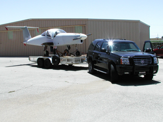
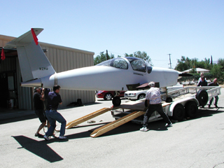
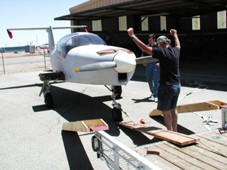
[May 22, 2002]
On Monday I borrowed a friend's Escalade, a monstrous Cadillac SUV with a 345-hp engine. On Tuesday I went out to Mojave in the morning. The wind was blowing, unpromisingly, about 40 knots right across the road. I borrowed a trailer from Mike Melvill of Scaled Composites, and on Wednesday morning loaded the plane onto it. The fuselage, anyway; by the time we get all the other stuff that needs to travel with it into the trailer, the wings will require another trip.
Getting the airplane onto the trailer, which has a rail all around, was somewhat tricky. The cast of characters included me, Ray Henning, Russ Hardwick, and Bill Reid, who had a divine dispensation to show up whenever help is needed. Ray had a pair of loading ramps he had used when he trailered his T-18 to Whiteman. I bought a few 8-foot 2x12s and rented a comealong. Russ took the pictures. Here's the plane just starting to be loaded; the nosewheel goes up a ramp onto the trailer bed, and the mains go up onto the rails:
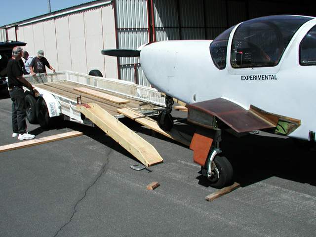
We then put the 2x12s on the rails and rolled the airplane forward on top of them, continually moving the rearmost one to the front:
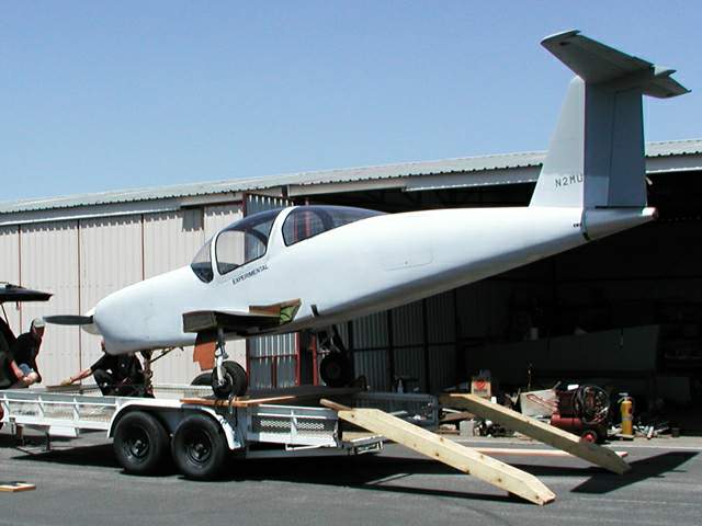
Once we got it more or less where we wanted it, a few hundred pounds of people hung on the tail to lift the nosewheel, and we slipped a support under it:
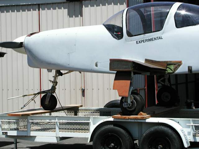
Tomorrow morning, Mojave.
[May 10, 2002]
With the help of Ray Henning, who is putting the finishing touches on a T-18 in a nearby hangar, I removed the wings. Nothing ever goes perfectly, however; I found that there were small fuel leaks where the rear spar attachment plate bolts to the spar web, and also in the sump drain assemblies. I believe these will be easy to fix. More annoyingly, the Dukes electric fuel boost pump is leaking; I think these pumps are expensive to overhaul -- utterances of their name are often accompanied by expletives -- but I haven't looked into it yet. Nor have I found a satisfactory trailer for hauling the plane out to Mojave. Furthermore, after storage for 20 years both of my Collins comm radios failed after being exposed to electric current, and my ancient but once reliable Silver Fuel Guard has turned into a random number generator. Experience with the first Melmoth has taught me philosophy, however; I know that all things must pass. Sooner or later all these devices will be restored to service, and occasionally all of them may even work at the same time; and so I am not discouraged, and place my faith in the Service Department.
I reflected for a long time on where to put a cold air inlet for cabin ventilation. John Thorp put his on the back of the canopy; it works because pressure there is relatively high and because low pressure around the winshield/canopy seam pulls air out of the cockpit at a great rate. That location, and most of the other usual ones, such as the base of the windshield or the leading end of the dorsal fin, are unavailable because hot air from the engine is flowing over the top of the airplane. I finally cut a two-inch hole in the firewall and installed a butterfly salvaged from Melmoth 1. Eventually I'll run a duct along the bottom cowl to the inlet, but for the time being I'll just use a length of SCAT hose.
[April 27, 2002]
The list of things to do gets shorter. The tail tie-down assembly, which I thought would take "a couple of days" to machine, took more like a week. The shimmy damper, whose design, creation and installation were compressed into the deceptively compact phrase "install shimmy damper," took a couple of weeks. The damper, which is a component of most steering systems (but absent from shopping carts, whose castering wheels therefore sometimes wobble annoyingly), consists essentially of a sealed hydraulic cylinder with a small hole in the piston through which fluid can pass. Having to force fluid through the hole makes it hard to move the piston rapidly and provides the "damping" that is required to avoid nosewheel wobble. Typically, the cylinder is attached to the nose strut and the shaft and piston to the rotating portion of the nose gear via the "scissors" linkage.
The one I made was constrained by the requirement that it be as short as possible, so as not to poke out of the well when the gear is retracted. I failed of this goal; it pokes out by a quarter-inch or so, and one of the nose gear doors will require a slight blister. In the interest of keeping everything as short as possible, I dispensed with the conventional piston and O-ring and used instead a thin steel disk, about the size of a quarter, on the quarter-inch stainless-steel shaft. It clears the three-quarter-inch bore by about a thousandth of an inch, and this gap provides the necessary leakage.
Here is the working drawing -- indistinguishable from da Vinci's, except that I write forward.
![]()
The Lord Company, maker of engine mounts among other things, sells a replacement shimmy damper for Cessnas that uses no hydraulic fluid; instead it relies on the friction of a rubber packing to provide damping. The Lord product is too large for my application, but if I had known how to make a smaller one, I could have made my damper more than 1.5 inches shorter than it is.
I have disposed of all the discrepancies identified by the FAA inspector, and am inquiring around about a trailer suitable for hauling the airplane out to Mojave.
March 22, 2002]
As of the middle of March, the list of items needing to be taken care of before Melmoth 2 could fly was down to five. They were:
Install a tail tie-down
Install door quick-releases
Insulate firewall shelf
Drill out guide bushing in left wing
Install
shimmy damper
Hard points for anchoring the tail tie-down already exist. The two wing tiedowns consist of 1/2-inch threaded sockets into which eyebolts would have to be screwed in order to tie down the airplane. The tail tiedown will be the same. It involves getting some aluminum plate and machining it to a particular shape; this will probably take a couple of days. The door quick releases, likewise, involve some machining which I have been putting off for a long time; they also require lengths of cable with crimped ends which I will have to order from a local parts store, All Aircraft Parts in Van Nuys. The idea of the quick-releases is to make it possible to jettison the door(s) in case I have to bail out during flight testing. Because of the design of the door hinges, however, it's possible that they would not fly free of the airplane even if the hinge pins were removed; it's even possible that they would jam partly open. So I may decide that, given that the risk of having to bail out is slight anyway, I will skip this step.
The guide bushing is an embarrassment too idiotic and complicated to explain. It will either be over very quickly or it will turn into a can of worms.
Most of the firewall is made of a special fireproof composite sandwich, but there is a 4-inch-wide shelf in the middle that is just plain fiberglass. This requires a fireproof cover -- some kind of ceramic cloth or pillow, I suppose.
The shimmy damper is a big pain. I'm not even sure it's needed, but as someone pointed out when I asked him what he thought, a shimmy damper is a lot cheaper than a propeller. The nose gear is from the original Melmoth, but it has been turned around, with the result that the original shimmy damper no longer fits in the wheel well. A shimmy damper should be easy to make, but I have to get the airplane up on jacks first to be able to cycle the gear and see what kind of space I've got; and to jack it up I need a tail tiedown (because the wing jack points are aft of the empty CG).
The first FAA visit took place on March 15. The inspector spent the better part of an hour going over the airplane, named a few discrepancies -- mostly floppy wires that needed to be tied down better, and bolts that didn't have enough threads sticking out past the locking insert in the nuts -- and said I could take it up to Mojave and he'd give it a final inspection there.
One of the places where the bolts weren't long enough was the rudder balance weight. I had to take the rudder off the airplane to fix the problem. That was easy. I also had to replace a bolt in the elevator actuation mechanism at the top of the fin. For some reason, when I put in the new bolt a slight interference appeared at one point in the elevator travel. I thought it was a rivet head on a bellcrank rubbing against the trim actuator. This turned out to be wrong, but I didn't find that out 'til later. First I took the bellcrank out, replaced the offending rivets with flush ones, and machined some material out of the elevator actuating pushrod to make it lighter (when I first made it, back in the Eighties, I didn't have a milling machine).
When I set out to put the whole thing back together, I found that the aft portion of the intersection fairing (which the French call a "salmon," by the way) would not slide into place unless the rudder was deflected to one side. I tried to deflect the rudder by rotating the nosewheel with the towbar, and found that the rudder was only moving 10 degrees to each side. It's supposed to move 25. I traced this problem to the brake pedals, which I had modified to increase their mechanical advantage. In so doing, I had set up an interference between the pedals and their supports. I rearranged various items and got rid of the interference, only to discover that the rudder would now swing 25 degrees to the left, but only 10 to the right.
Further examination disclosed that the nut that secured the rudder cable to its actuating sector was installed backwards, and was colliding with the back of the firewall. There is insufficient clearance between the sector and the firewall, but nothing can be done about that now; I just have to be sure always to get that nut in right -- not that I will probably ever have to remove it again.
Finally the rudder travel was right, the aft end of the salmon slid into place, and the elevator interference -- which turned out to be due to some other parts after all -- disappeared. That process -- originally, just changing a bolt in a bellcrank -- took two days.
I'm not sure this clarifies why it should take 20 years to build an airplane, but at least it may convey the flavor of the final preparations for flight. You go back over everything, find problems, and in fixing them discover other problems. What looked like five steps turns out to involve 25. Eventually, you get them all - the series is not divergent -- but it takes several times longer than you expect. In fact, it takes several times longer than you expect even when you expect it to take several times longer than you expect.
[End or Beginning]