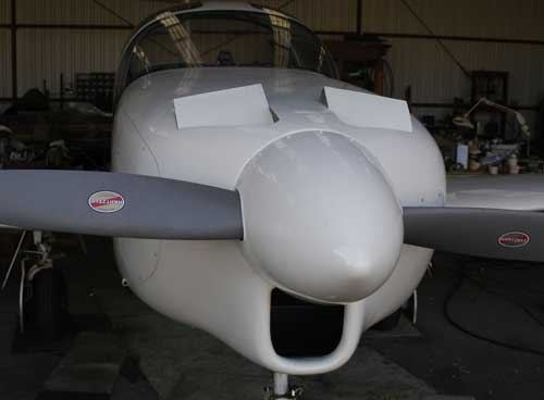
The original Melmoth (1973-1982) had a single air inlet below the propeller. I don’t remember why I adopted this design, but it can be rationalized in several ways. A single large inlet should be more efficient than two small ones -- everything else being equal -- because it has a larger ratio of area to perimeter. Another possible advantage is that to the extent that an inlet disturbs the air flowing over the airplane surface behind it, the single inlet affects less of the total surface of the cowling than the usual twin inlets, or an annular inlet (a slot all the way around the spinner) would. But these "advantages" are only theoretical; it would be very difficult to measure real effects, if any, or to separate them from those of other design elements. And so the most honest accounting for the single inlet would be to say that I liked the way it looked.
In that system, I used the downdraft baffling supplied with the original Continental IO-360-A engine, which had been taken from a Cessna 336. Because I used a propeller with a 7.75-inch extension built into the hub, there was sufficient room in front of the engine for the intake air to travel upward into the plenum above it. From there it flowed downward over the cylinders and escaped through variable-area outlets on the sides of the cowling near the firewall.
The variable-area feature was implemented with curved sheets of .025 aluminum bent around upon themselves at their leading edges and riveted, at their trailing edges, to the airplane skin at each side of the firewall. The result was two smoothly curved ramps that could bend inward between end walls. A bicycle brake cable ran from each ramp to a ratcheting control in the cabin. The outlets had a vertical dimension of 10 inches, and the width of the outlet slot could be adjusted between 1/2 inch and four inches. The airplane normally cruised with a total outlet area of ten square inches. It cooled very satisfactorily. The inlet area, based on a formula provided by John Thorp, was 0.35 times the climbing horsepower at 87 knots, or, in this case, about 65 square inches. The actual inlet channel was slightly smaller than this, however -- about 60 sq. in -- because the inlet area was measured at the "highlight", or most forward point, of the generously radiused lip.
It's worth noting that excessive cooling flow produces nothing but drag. But a moderately oversize inlet is not a problem, provided that it has well-contoured lips. Only as much air enters the cowling as can escape, and so the best way to control cooling flow is to seal the cowling and baffles tightly and vary the area of the air outlet.
My choice of the side of the fuselage, rather than the more conventional bottom, for the outlet location was probably influenced by Thorp's T-18, although the T-18's outlets were, by Thorp's own admission, far from ideal, being much larger than they needed to be.
The cowling for Melmoth 2 was made in a mold that used, as its starting point, the cannibalized cowling from the destroyed Melmoth 1. It therefore had the same medial, or as one person styled it, "lemonsucking" inlet. For reasons that I no longer remember, I decided to try updraft cooling this time; perhaps I was influenced by Burt Rutan's fondness for it. Rutan placed his outlets above the engine cylinders; but I decided to place mine farther forward, because I was aware that there was an area of low pressure near the front of the cowling top. I'm not sure how I knew this, but it is intuitively obvious once one has seen the pressure distribution around an airfoil.
To test the idea, I used my lofting program to obtain a vertical, longitudinal cross-section through the fuselage nine inches off center, roughly at the center of the proposed outlet. Having converted the section dimensions into an airfoil format, I ran the shape though the Eppler airfoil-analysis code. (I did not have 3D flow-analysis software at that time.) As expected, it showed a large negative pressure on the forward upper surface of the cowling. Furthermore, the pressure became more negative with increasing angle of attack, just like the pressure on the front upper surface of an airfoil.
The significance of this information was that an extraction effect could be obtained by placing the outlet under the area of low pressure, and the ratio of the extraction pressure to the dynamic pressure (as reported, for example, by the airspeed indicator) would increase at lower speeds, just as one would wish.
To quantify the extraction effect, I more recently used a 3D computational fluid dynamics (CFD) program to obtain pressures at three different outlet locations at zero, four, and eight degrees nose up. (A normal climbing attitude would be about four to six degrees nose up.) The blue line on the graph at left represents upper-surface pressures on the cowling, from the base of the spinner back to the firewall; the angle of attack is four degrees. The suction peak near the front is obvious.
 Here are the CFD results
for outlets on the top, side, and bottom of the cowling:
Here are the CFD results
for outlets on the top, side, and bottom of the cowling:
Angle Top Side Bottom
0.0 -0.35 (116) -0.06 (103) -0.06 (103)
4.0 -0.52 (123) -0.10 (105) 0.00 (100)
8.0 -0.69 (130) -0.16 (108) -0.07 (103)
In
this scheme, the dynamic pressure is always 1.0, and so the pressure
differential across the cylinders, which determines the effectiveness
of the cooling, is the absolute difference between 1.0 and the pressure
coefficient at the outlet -- for example, 1.52 for the top outlet at
four degrees. Since the dynamic pressure changes in proportion to the
square of the speed, the square root of the pressure difference
represents an equivalent speed ratio for a system with zero extraction
effect. The numbers in 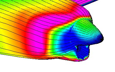 parentheses
represent an "equivalent speed" for the cooling flow at 100 knots. For
example, at four degrees angle of attack the top outlet yields the same
pressure differential across the engine at 100 knots as an unaugmented
flow would yield at 123 knots, because 1.23 is the square root of 1.52.
In the CFD "spectrum plot" at right, violet represents low pressure,
green neutral, and blue high. The region of low pressure on the front
upper surface is easy to see.
parentheses
represent an "equivalent speed" for the cooling flow at 100 knots. For
example, at four degrees angle of attack the top outlet yields the same
pressure differential across the engine at 100 knots as an unaugmented
flow would yield at 123 knots, because 1.23 is the square root of 1.52.
In the CFD "spectrum plot" at right, violet represents low pressure,
green neutral, and blue high. The region of low pressure on the front
upper surface is easy to see.
This analysis is a simplified one. It ignores many factors, such as the efficiencies of the inlets and outlets -- always less than 100%. But all cooling systems suffer similar inefficiencies, and so the relative rankings of the systems should remain more or less the same. Another adverse factor in this installation is the fact that the cooling air in the updraft system will pick up some heat from the exhaust pipes and turbocharger before reaching the cylinders. Finally, the cylinder heads of the Continental 360 have most of their finning on the top; the effectiveness of updraft cooling will depend on the ability of the baffling to force the available airflow to follow the cylinder-head contours..
Updraft cooling places the accessory case in cold air, eliminating the need for blast tubes on the alternator or magnetos. On the other hand, it is inconvenient for several mundane reasons. One is that it requires that the bottom bowl of the cowling be well sealed, whereas the exhaust needs to get out downward and various other junk, like dripping oil and rainwater, needs to escape from, not collect in, the lower cowl. The nosewheel well also has to be sealed off from the rest of the cowling; I solved this problem the same way Cessna and Beech have in the Centurion and Bonanza, using an aluminum box as both a wheel well and a bed mount for the engine.
I am not aware of other cowlings that use forward upper-surface outlets for engine cooling air, but I do know that the cowling for the German BMW 801 radial engine used in the Focke-Wulf 190 vented the oil cooler exhaust through a narrow circumferential slot near the cowling's leading edge. The oil cooler itself consisted of segments of a long slender ring that nested inside the forward portion of the cowling. Air entering the cowling reversed direction to pass through the cooler, and then reversed again to flow out through the narrow nozzle-shaped slot. Aerodynamically, this system is equivalent to mine.
Practice vs Theory (as of 12/03)
After 80 hours of flying and a number of minor adjustments to the cooling system, I am able to assess, at least to some degree, its effectiveness.
Generally speaking, it works fine. Some modifications, yet to be figured out, are still needed to even out the temperatures of the cylinders, but there is no difficulty keeping the temperature of the hottest cylinder (#6) below 400 deg. F at all times. This is well within the green. The four rear cylinders run at or below 340 in cruise.
The intended extraction effect from the forward outlets is real, though small, as can be demonstrated by climbing at high power and low speed, and then increasing speed. Contrary to normal expectation, the cylinder head temperatures -- particularly those of the front cylinders -- rise. The most likely reason for this behavior is the expected suction over the outlets at high alpha. Presumably the extraction effect continues to exist at lower alpha/higher speed, but it may not be especially significant.
The updraft flow seems to work fine, but it's necessary to keep in mind that the cylinder head temperature probes are located on the cold sides of the cylinders. A thorough evaluation of the cooling system, baffles, etc. would require measuring temperatures all over the cylinder heads and barrels. I don't have the equipment to do this.
Some concerns have been expressed over preheating of the cooling air by the exhaust pipes and turbocharger. This is certainly taking place; the air on the "cold" side of the baffles, near the firewall, is 25 deg. C warmer than ambient. Even the engine breathing air experiences a 10-12 deg. C temperature rise during its trip through three feet or so of SCAT ducting along the bottom of the cowling. I have no idea how detrimental, if at all, the preheating is; it is probably at least partly responsible for the oil temperature running at 90-100 C, rather than the factory-recommended 80.
I was surprised to find that the temperature of the cooling air in the upper plenum, after passing over the engine, is only 60 deg. C (140 F). I expected it to be hotter. It seems that too much air is flowing through the system, so that the heat rejected by the engine is being diluted. Until I make the cowl flaps moveable, however, I can't test that hypothesis.
Currently, the cowl flaps are fixed in a more or less fully open position. Temperatures drop to the bottom of the green, and even lower, at low power settings. At high cruising settings (ie 70% power), temperatures look good now. It's not clear whether choking the outlets will significantly affect cooling in cruise. If it does, I may find that I have created an odd system that cools better at low speed than at high. That would be amusing.
Further observations (9/05)
After flying more than 200 hours, I feel somewhat less satisfied with the cooling system than I did originally. The temperatures of the left front and right rear cylinders are considerably higher than those of the rest, and get up to 440 F. during a long hot-weather climb. In cruise, temperatures are moderate -- but not so low as to make it urgent to close the cowl flaps. Some other builders, who have taken different approaches to cooling flow, have managed to achieve lower cylinder temperatures with much smaller inlets and outlets than I am using, and presumably with less drag.
Re-reading the 1970's work of S. J. Miley of Mississippi State, who is responsible for the current rage for small circular inlets located away from the spinner, I find that my cowling design violates some of his principles, for instance in having a large high-pressure plenum and a small low-pressure one -- the opposite of customary practice. Miley actually recommended making the high pressure plenum's cross-sectional area equal to that of the inlet(s), so the the plenum is not so much a plenum as a duct. Hence the common use, in high-performance airplanes like Formula 1 racers, of plenums that are built directly onto the engine. That arrangement also makes it easier to prevent leakage. In any case, I suspect that my cooling efficiency is poor, in part because my air outlets are somewhat obstructed by engine components, and in part because of flow separation in the inlet to the plenum. Lagging the exhaust system to insulate it from the cooling air might help, as might careful shaping of the air inlet path.
I expect that at some point I will have to make a concerted attack on the cooling drag, which I assume (without proof) is now excessive. First, however, I feel that I should eliminate all other sources of unnecessary drag. For example, I know that my main landing gear doors are protruding slightly when the gear is retracted. There are no nose gear doors at all. There may be some drag from leakage around the windows. It is likely that some sanding and repainting would permit more laminar flow on the wings. Once these items have been dealt with, cooling will be the last remaining place to look for improvement.
It would be interesting to know how little drag an airplane of this size can reasonably be expected to have. A tabulation of CAFE race results discloses very few four-seat airplanes with equivalent flat plate area (F) lower than 3.0 square feet. Melmoth 2's is currently 2.55. The lowest is the Rutan Catbird (actually, a five-seater, but slightly smaller than Melmoth 2 in both cabin volume and wetted area), to which an F of 2.0 square feet is attributed. The race basis was 192.3 mph at 8.9 gph, a performance which Melmoth 2 can match at 12,000 feet; the Catbird presumably did it at a lower altitude, but not that much lower. Uncertain assumptions about fuel specifics and propeller efficiency cast doubt on all calculations of F. At any rate, the Catbird was the all-time CAFE champion. If, as seems reasonable, I take it as possessing the last degree of refinement in streamlining and cooling, then it would appear as if there might yet be hope for measurable improvements in Melmoth 2.
Still more further observations (7/06)
Although the left front and right rear cylinders were still hotter than the others, refinement of the cowl flaps had brought temperatures down so far that in economy cruise the engine was too cold and the cowl flaps needed to be closed. I accordingly made the cowl flaps adjustable in flight. Pictures of the flaps and their actuating mechanism can be found in the Progress section, in entries for May and June of this year. Outlet area can be adjusted from 19 square inches to 82. Inlet area is 55 sq. in. at the smallest part of the throat.
The equivalent flat plate area of the airplane, which was 2.55 sq. ft. less than a year ago, is now 2.25 sq. ft. The principal agent of change was the installation of doors on the nosewheel well, though flap track fairings and other detail improvements also played a part. I have not yet measured the effect on speed of opening and closing the cowl flaps.
Morether observations (11/06)
The adjustable cowl flaps have no obvious effect on speed, but they do allow good control of cylinder head temperatures. I normally cruise with them fully closed -- though "fully" is not really fully, because for some reason -- probably bulging of the cowl top in flight -- they always remain about a quarter-inch open at the trailing edge. I doubt this has much effect on anything, but I will eventually fix it by moving the closed limit switch from the actuator to the cowl flap itself. Keeping the cowl flaps closed in cruise has had the effect of raising the oil temperature by about 8 deg. C. I have still done nothing about the two cylinders that are hotter than the other four, but I have noticed that for some reason in climb the disparity disappears.
Resolution of the unequal-cooling problem (4/07)
It seems perfectly obvious in retrospect, but it took me several years to recognize that the problem of the two hot cylinders was due to the baffling and not to some sort of mysterious dynamics in the cowling. I knew, rationally, that the large air inlet and the very large plenum beneath the engine ought to mean that the air there was essentially at a standstill and was pressurized to a reasonable fraction of the total pressure -- the diffusion losses would be the same as in any other cowling using a plenum -- and so the flow across the cylinders was most likely unaffected by air motion within the plenum. I would visualize the situation as resembling a large tank of water with a hole in the bottom, and the engine, inverted, blocking that hole. Nevertheless, I could not see how the baffling of cylinders #1 and #6 was so different from that of the other four that they would run as much as 80 deg. F. hotter, and so I kept thinking that some kind of mysterious blockages or eddies or other aerodynamic effects were responsible. The fact that a nose-high attitude in climb tended to reduce the temperature disparity encouraged me in that belief.
The only blockage, as it turned out, was mental. I date its removal from April 22, 2007, when I was in Paso Robles at a meeting whose purpose was to plan some flight tests of some of Javier Arango's World War I airplanes. Always eager to pick a brain when one wanders within range, I described my cooling issues to Paul Robertson, who owns Aeronautical Testing Service in Arlington, Washington. He said that such things were not unusual, and that the solution always lay in tinkering with the baffling. By sweeping aside the whole matter of flow dynamics within the plenum, his remark, together, perhaps, with an article on baffling that happened to appear in Kitplanes magazine this month, made something click. It enabled me to perceive what should have been obvious all along: that what the two hot cylinders had in common was that their exhaust ports were not adjacent to another cylinder.
I inspected the environments of the "cool" cylinders and observed that the neighboring cylinders' intake port geometry formed a converging duct around the unfinned outer surface of the exhaust port. I accordingly removed the baffling from the #6 cylinder (it's a little easier to remove than that of #1, so I attacked it first) and added some bits of sheet metal whose purpose was to imitate that duct -- that is, to contain and accelerate the air flowing over the surface of the exhaust port. A short test flight showed that this change had been quite effective; the #6 CHT had dropped by 50 deg. F or so. Similar modifications on the #1 (right rear) cylinder produced the same result.
Research done on cylinder cooling back in the 1920s and 1930s showed -- if it was not already sufficiently obvious -- that air had to be kept flowing over every part of the cooling fins; air that became static or stalled did no good. Baffles therefore rest on the cooling fins -- air going by outside the fins does nothing -- and wrap around the downstream sides of cylinders, allowing air to escape through slots whose area is about the same size as the space between the fins. I had provided that kind of baffling on the downstream sides of my cylinders. But I had failed to appreciate the importance, for heat transport, of maintaining flow velocity over all parts of the upwind sides of the cylinders as well. The exhaust ports were in relatively stagnant, albeit cool, air; they needed to be enclosed in channels through which that air would travel at reasonably high velocity, pumped by the pressure difference between the two plenums.
Further possibilities
In the spring of 2010 I finally solved the persistent problem of unexpectedly high oil temperatures by providing a duct for the oil cooler that picks up air from below the exhaust pipes, before they have a chance to pre-heat it, and discharges it directly to the outside, so that the cowl flaps do not throttle the oil-cooling air along with the cylinder-cooling air. It remains unclear why this duct should be necessary, since the oil cooler is integral with the Continental engine and is designed to share the cooling plenums with the cylinders. Pre-heating of the oil-cooling air by the exhaust pipe was a big factor, but not the whole story.
I continue to toy with the idea of replacing the single medial air inlet directly behind the propeller with two inlets on the lower quarters of the cowling, 8 or 10 inches behind the prop. The location of the present inlet would be raked aft and faired, somewhat like the nosewheel fairing in the cowling of a Cessna 210. Air entering through the two inlets would have an unimpeded path into the cowling and could even benefit from some small amount of controlled internal diffusion in lieu of the present chaos. At the same time, the intake manifold atop the engine would be reversed, removing the transverse tubes from their present position blocking air on its way to the outlets. The throttle body would be on the cool side of the baffles, and the path from the turbocharger to the throttle body would be much shorter and more direct than it is now. If one had had the whole system to design from scratch, this is how it would have been arranged -- assuming, that is, that one had not decided to use downdraft cooling after all.
The deterrent to this project is that the net result might be imperceptible.
Update seven years later
The Progress section of this site describes various changes made to the cooling system since 2010. The most significant one was the reversal of the intake manifold in order to remove the transverse tubes blocking the path of air to the cowl outlets and to place the fuel controller/throttle body on the "cold" side of the baffles. I have also wrapped some of the exhaust pipes with insulating material in hope of reducing the transfer of heat to the cooling air prior to its arrival at the cylinders. (The product I used has begun to deteriorate, however.) Late in 2014 I modified the cowling air inlet to incorporate vanes whose purpose was to force some cooling air to follow the inner surface of the cowling, from which entering flow would normally separate. The original idea was to direct air toward the oil cooler duct inlet without its passing near the exhaust pipes. This was accomplished, but an unexpected collateral benefit was to bring the temperatures of the cylinders on opposite sides into fairly close agreement with one another.
Late in 2017 I added a deflector to the floor of the plenum on the left side, the purpose of which was to direct the theoretical stream of cold air flowing along the bottom surface upward toward the oil cooler intake. This had the effect of lowering the air temperature in the duct by about 10 degrees F, and the oil temperature by five.
Although the modifications I have done have produced improvements in various aspects of cooling, none of them has had a noticeable effect on speed. In other words, nothing I have done has significantly reduced cooling drag. Reflecting on this fact, I have concluded that cooling drag cannot be much greater than, and is probably less than, the effect of bringing to a halt a stream tube whose area is the lesser of the cowling's inlet and outlet areas. On the assumption that the cruising outlet area is smaller than the inlet area, this statment can be rephrased as "the equivalent flat plate area of the cooling system is equal to or less than the area of the outlet."
The inlet area of the cowling, depending where you measure it, is around 60 sq. in. My cowl flaps vary the outlet area from a maximum of 80 sq. in. to a minimum of 19. I normally cruise at the minimum outlet area. Nineteen square inches is 0.132 sq. ft, or about 5.6% of F for the complete airplane. If I eliminated cooling altogether the difference in speed at 75% power at 12,000 feet would be about 4 knots. The question, however, is not whether I can eliminate cooling drag altogether -- I obviously can't -- but how much lower than 5.6% it can possibly be.
I am aware that cooling drag involves components other than momentum loss of air passing through the cowling. Other components are the disturbance to air flowing around the inlet, the disturbance behind the outlets, and disturbances due to leakage through cowling seams. I am assuming, without evidence, that those increments are more or less balanced out by my conservative assumption that no momentum is recovered at the outlet.