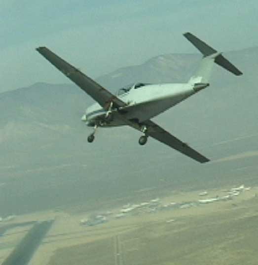
Flying...at last! A frame from the first-flight video, Mojave, 11/1/02. Civilian astronaut and ex Scaled Composites test pilot Mike Melvill is flying chase.
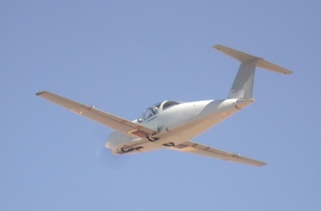
And from the first flight with gear retraction, before discovering that the gear wouldn't come back down:
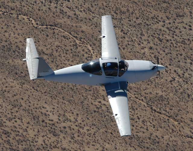
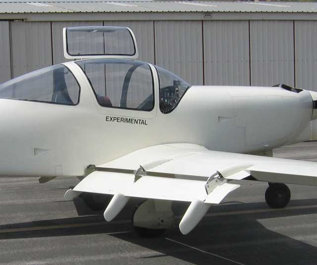
A couple of months later, showing the general proportions:
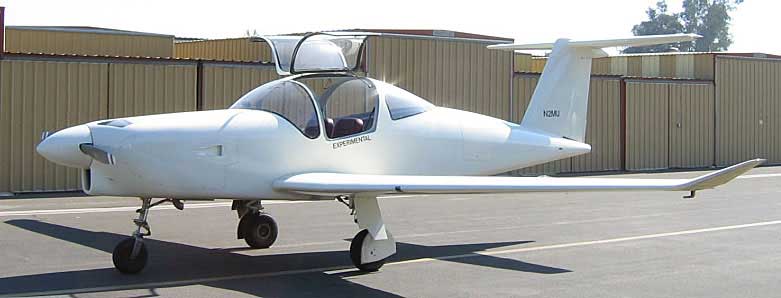
And with the current brush-and-roller paint job:
What comes next is a tour of the airplane's innards. The pictures were taken at different times and reflect different stages of modification, finishing, etc. Since they were taken, much of what they show has been hidden from view by floor panels, armrests, and so on.
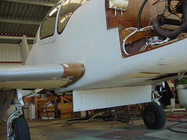 |
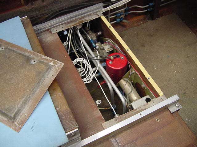
The airbrake is a graphite sandwich with a half-inch foam core. It is operated by a single-acting (that is, push only) hydraulic cylinder. A couple of springs pull it shut when pressure is released. The piston engages the brake by means of a slotted fitting so that the brake can be pulled open by hand. In the compartment above it are the fuel and hydraulic systems. The white tank at the top of the image is the reservoir for both the brakes and the hydraulic pump. A dam divides it into two compartments, so that it can be filled at one point but if either system springs a leak it will not drain the other. The battery box is in the lower right corner of the cowling, against the firewall. The flush oval door, held shut by a chip of neodymium magnet, covers the external power socket.
|
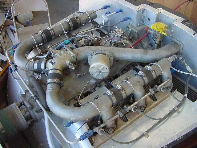 |
The Continental TSIO-360-F engine is the same one as was in Melmoth 1. The drum-shaped gadget in the center of the picture is the boost limiter, which keeps the manifold pressure below 41 in. Hg. I seldom use more than 34. The intercylinder baffles, usually found on the bottom of the engine, are on the top because the cooling flow is from bottom to top. Since this picture was taken, I've moved all the fuel system components to the cold side of the baffles in order to avoid hot starting problems and rough idling on hot days. I've also added an oil separator -- about the size of a small frozen lemonade can -- that is miraculously successful in keeping oil from blowing out of the crankcase. These changes are visible in the next picture.
|
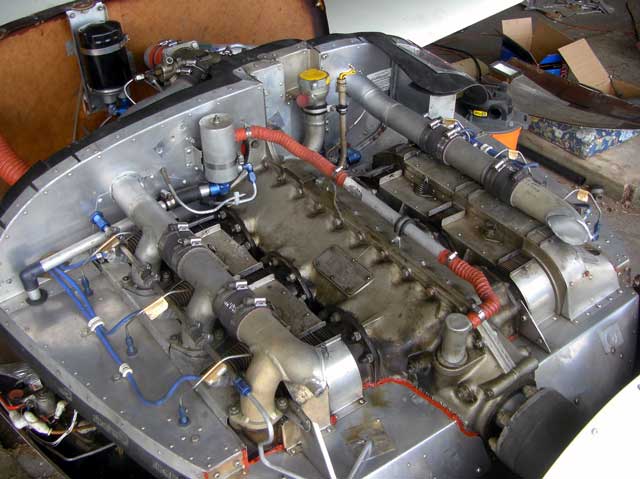 |
A more recent view of the engine than the one above. The oil separator is visible (top, left of center), as are the fuel lines that come up from the relatively cool plenum below the baffles and spend as little time as possible on the hot upper side. The intake manifold has been reversed in order to remove the transverse runners from the cooling air exit path and to put the throttle-cum-fuel-control on the cold side of the baffles
|
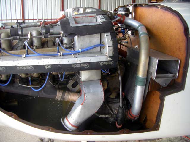 |
The Rajay turbocharger is below the engine, supported on a weldment that is secured to a diverter plate that I placed between the crankcase and the oil cooler (the rectangle behind and below rear cylinder) to send oil to the externally-mounted filter. This diverter was necessary in Melmoth 1 because the normal location for the oil filter attachment interfered with the nose gear retraction. It also provides a convenient mounting surface for the turbo support, so I kept it. Actually, the normal filter location is obstructed in this airplane too. The foam air filter is above and behind the turbo, against the firewall, inside the aluminum box whose open end faces you. A flush inlet in the cowling side feeds air into the box. See Progress for Sept. 27, 2004. The long vertical duct between the baffles and the firewall carries turbo discharge air to the throttle-cum-fuel-controller, which is now on the cool side of the baffles. The boost limiter has been discarded, at least for the time being.
|
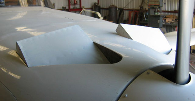 |
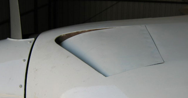
After passing through the cylinder fins, air flows to the front of the upper plenum and out through faired slots. In theory, the pressure here should be low enough at high angles of attack (that is, in slow or climbing flight) to provide an extraction effect (see Cooling Flow). The cowl flaps, which are electrically operated, are in the closed position (left, below) for economy cruise and in mild to cooler weather. For takeoff, the rear edge opens about an inch. During taxi and after landing, the fully open position (left, above) is used to scavenge hot air from the cowling.
|
 |
|
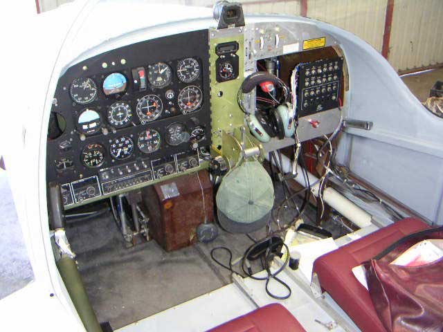 |
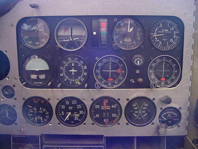
The panel is, well, classic. The airspeed indicator began life in a DC-4. The rectangular thing between the artificial horizon and the altimeter is a Safe Flight angle of attack indicator.The white edgewise meters at top right are fuel quantity indicators. Toggle switches below them select whether the inner or outer sender is being used. The little yellow switch between the meters turns on the automatic tank switching system, which changes tanks every few minutes in order to keep the airplane laterally balanced. The red vernier with the headset hanging on it is for mixture; the turbo wastegate vernier was later installed in the hole below and to the left of it. The single sidestick controller is at bottom left. The large white torque tube on the right connects the main and nose landing gears. |
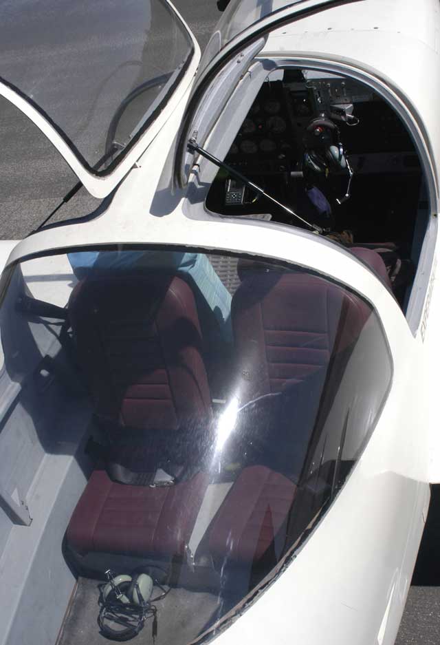 |
The back seats face aft, and have the same amount of shoulder and leg room as the front seats. When they are not in use, their backs fold down easily. Each seat is held in place with a single screw and can be removed to increase baggage space. The reason for the aft-facing arrangement is to bring both the centers of gravity and the heads of the occupants closer together in order to minimize CG travel and permit the canopy to have a properly streamlined shape. I used to think that having heads close together would make it easier to talk, but it's so noisy that everyone wears a headset and communicates via intercom. |
 |
When this photo was made, toggle switches between the OBSs selected which one the autopilot was tracking and reversed the signal for back course approaches; the orange warning light indicated when sensing was reversed. Now the selector is a rotary switch that includes the option of tracking a GPS course, and because of an elusive wiring error the orange light no longer works at all. The toggle at the lower left selects whether the oil temp gauge is indicating oil or upper deck air temperature, and has been the cause of much ridiculous confusion. The knob above the EGT gauge selects which bank of cylinders the CHT is reading. The spare needle -- painted sky blue -- on the twin-engine manifold pressure serves as a backup altimeter. The Soviet-style moving-airplane attitude indicator seen here, which I liked quite a bit, quit working and has been replaced by a conventional one. The edgewise meter to the right of it is the invaluable Safe Flight SC-100 angle of attack indicator. The markings on the airspeed indicator refer to some other airplane. The radios are installed in a horizontal rack -- for cooling -- at the bottom of the panel.
|
 |
The compartment above the airbrake is also accessible from inside the cabin. Under the left front seat are the electric fuel pump (red), gascolator, fuel shutoff valve, fuel filter, and the automatic tank switching system (the light gold-colored cylinder is a gearhead motor). The entire fuel system is mounted on a single aluminum plate. This seemed like a good idea at the time, but it makes things rather hard to get at. At least vapor lock should not be an issue, because the boost pump is below the lowest point in the fuel tanks.
|
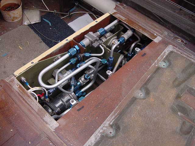 |
Beneath the right front seat is the hydraulic system. The pump, originally used in a T-33, runs only when needed; there is no accumulator. The operating pressure is 1,200 psi. Landing gear, flaps and airbrake are hydraulic. The hydraulic system, like the fuel system, is mounted on an aluminum plate and can be removed in one piece. If you don't remove it to work on it, however, the packaging is too tight for convenient access. Melmoth 1 had a sprawling hydraulic system with snarls of lines running everywhere. Reacting against that mess, I went too far in the other direction.
|
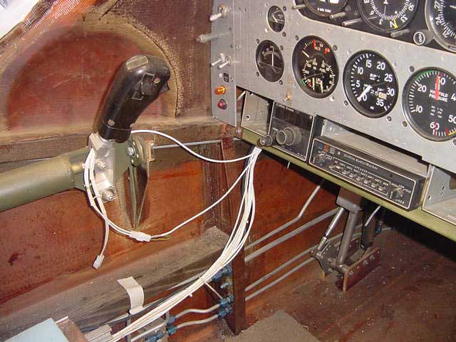 |
The sidestick. The switch on the right side of the grip is the press-to-talk switch. The one on the front of the grip is the autopilot interrupt, which temporarily releases the autopilot servo clutch to allow maneuvering. The two toggle switches on the left side of the panel are the mags; the red button below them is the starter. The rudder/brake pedals are narrow and widely spaced in order to allow you to stretch your legs out between them.
|
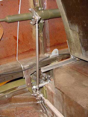 |
The aft end of the sidestick torque tube, behind the left front seat. The inner push-pull tube continues aft to the elevator; the outer tube, which is supported at its aft end by three small roller bearings, drives a vertical pushrod (unpainted) that in turn rotates an idler bellcrank. The purpose of the idler is to provide aileron differential -- more up travel than down. Since this picture was taken the autopilot servo has been installed against the sidewall and the seats have been upholstered and the interior surfaces painted (light gray). |
 |
The idler bellcrank. It has a short link to a short torque tube connected to the left aileron pushrod, and a longer tube going off to the right aileron. The slots in the green material (zinc chromated aluminum) to the upper left are the inboard flap tracks. The seemingly pointless pair of lugs extending toward the lower right were for a balance weight, should one have been needed because of the sidestick's rightward tilt when in its neutral position. The ailerons do flip into a right roll position on the ground, but the slight lateral imbalance does not seem to affect the flying qualities.
|
 |
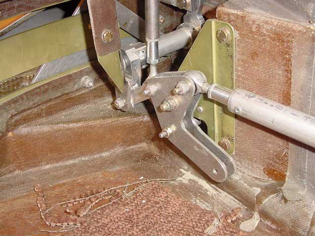
The right aileron linkage, just inside the right sidewall and behind the rear spar. The short torque tube is needed because the rear spar bends aft to make room for the tires. As a result, the pushrod running across the cabin is about four inches aft of the pushrod (the one with a touch of sky-blue) that runs out along the wing to the aileron. |
 |
The single-slotted Fowler flap is 115 inches long, has an average chord of about a foot, and travels all the way to the trailing edge of the wing before deflecting 30 degrees. Fully deflected, the flaps increase the wing area outside the fuselage by 20 percent. Each flap is operated by two hydraulic actuators, one inboard and one outboard. Their travels are different. To keep the right and left flaps, and the ends of each flap, in step with one another, each actuator is enslaved to a master cylinder in the fuselage, and the masters are all connected to a four-armed bellcrank, or starwheel. |
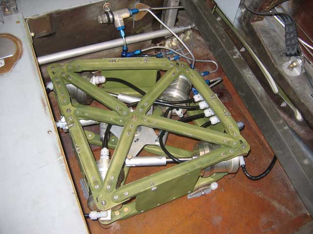 |
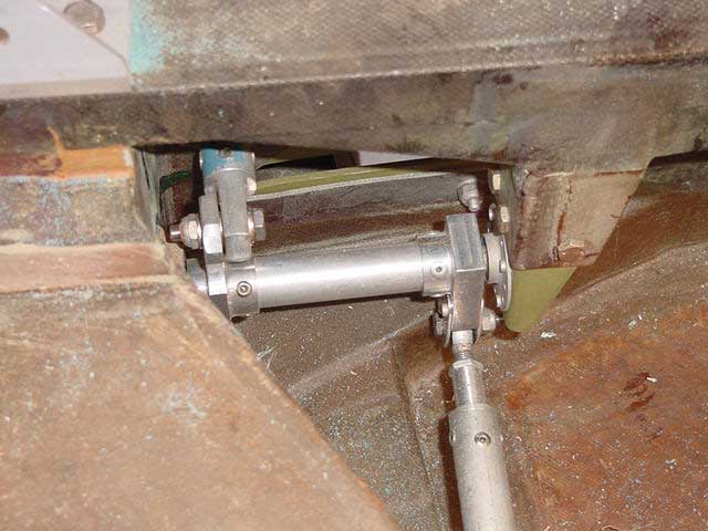
The flap synchronizing system is under the right back seat. The starwheel that keeps the four cylinders in step with one another is visible within the supporting frame, which has to be quite strong to withstand the forces that can potentially be developed by hydraulic cylinders 2.25 inches in diameter. |
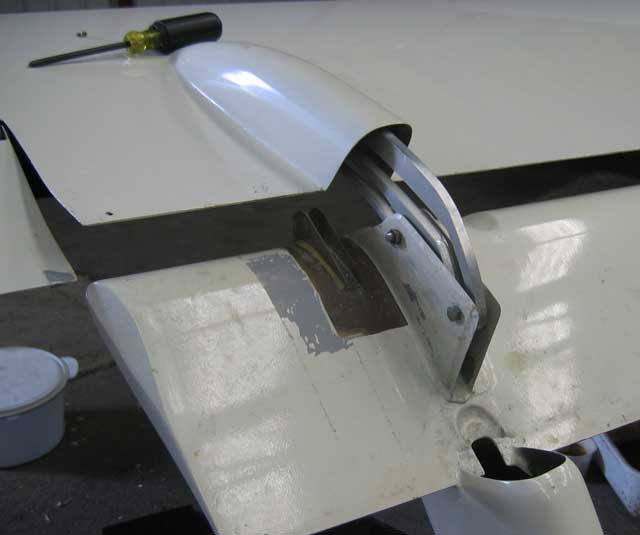 |
The outboard flap track. The tracks are enclosed in fairings. The tracks are above the flap rather than below it because it was easier to attach them to the rear spar that way. Normally, the outboard actuator attaches to the fitting just to the left of the track. |
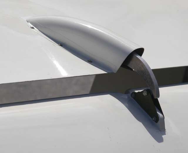 |
The middle flap track consists of a simple ramp or rail, supporting the flap only from above. It carries half or more of the total flap load. |
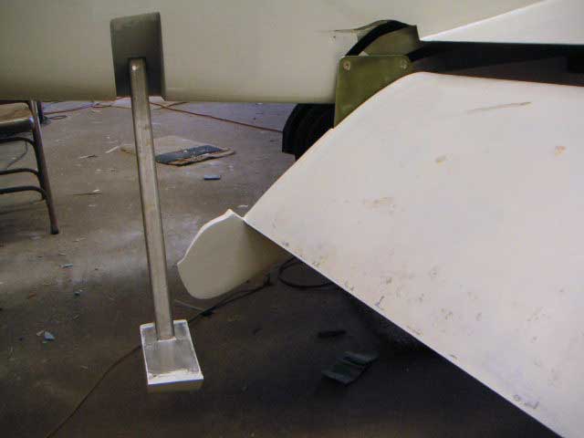 |
The track at the root of the flap is built into the side of the fuselage. The metal object at the left is a boarding step. These are supposed to be electrically retractable, but I haven't gotten around to that system yet, and probably never will. The inboard flap actuator is inside the fuselage; it is anchored aft of the boarding step and attached to the flap at the front roller. |
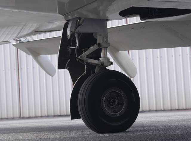 |
The main struts are from a Piper Cherokee. Because the Cherokee retraction geometry would not work in my wing, I removed the trunnions, machining down the upper part of the struts to a smooth cylinder which is now held within a sheet-steel weldment. The sway brace cum retraction linkage is a hybrid of Piper's parts and mine. The tires are 600x6, the brakes have heavy-duty (3/8-inch thick) disks. When the gear is retracted, the wells are completely enclosed. Each main gear assembly weighs 35 pounds. This is the right gear; forward is to the left. |
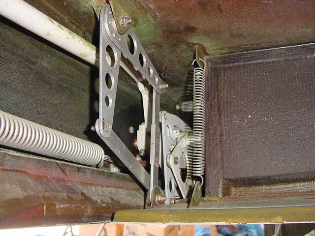 |
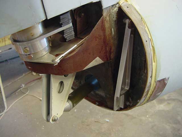
The main wheels retract inward. The inboard doors open to allow them to pass and then close after them, all under the control of a ballet of bellcranks, some of which are visible here. The main bellcrank rotates slightly overcenter to lock the gear in the up position; to unlock it, the main shaft has to be rotated back a few degrees. Normally the hydraulic cylinder does this, but in case of a hydraulic failure it can be done manually from inside the cockpit. |
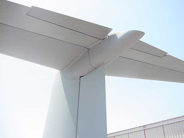 |
The T-tail intersection with its fairings in place. The elevator deflects 25 degrees upward and 15 downward, and cruises with a downward deflection of about 3.5 degrees. When this picture was taken, the trim tabs were also servo tabs, intended to lighten the stick forces in pitch; note that with the elevator deflected downward, the servo tab was deflected upward to help it along. If the elevator were up, the tab would be down. Combining trimming and servo effects in the tabs resulted, however, in insufficient trim authority, and I got rid of the servo action, dedicating the entire tab travel to trim. |
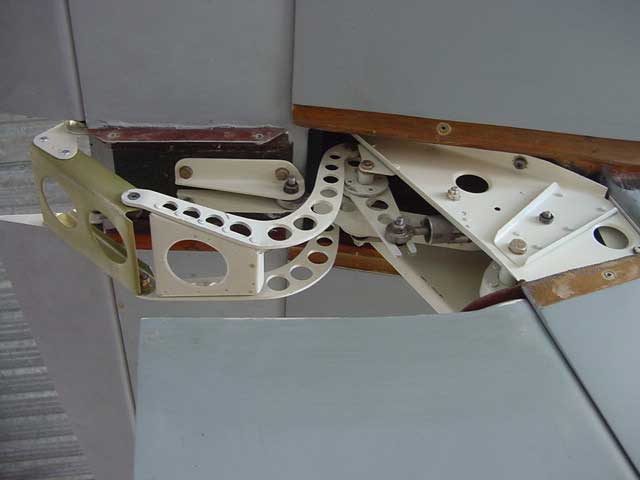 |
This was the original trim apparatus, located at the T-tail intersection. It no longer exists, but its picture is included here to illustrate my genius for gratuitous complexity. The cylindrical thing with the rod sticking out of it is a Cessna trimmer, which was driven by a chain-and-sprocket arrangement via cables from the cockpit. The trim tabs also had a servo action, intended to reduce elevator forces in light of the small mechanical advantage of the sidestick. This turned out to be unnecessary, and I changed it to a trim-only system. |
i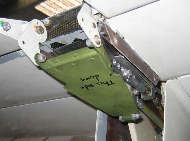 |
This is the revised and much simplified trim system. The previous picture gives a view of the general environment, but the mechanism inside is now completely different. The wedge-shaped green thing is a very light but rigid box made of .010 aluminum; it connects the right and left trim tabs to a common idler which is free to rotate about the bolt that attaches the elevator pushrod (round green thing) to the two white angles that are visible in the previous picture, but hidden in this one. The trim jackscrew is mounted on the underside of the elevator. It drives the right tab, whose motion is conveyed to the left tab by way of the idler and the wedge-shaped box. The jackscrew is rotated by square brass tubes that accommodate the motion of the elevator by telescoping. They go to a sprocket on the fin spar; a length of bicycle chain runs over the sprocket, to which cables convey the trim setting from a wheel in the cockpit. |
 |
The rear bulkhead and fin spar attachment. The raggedly stacked things are lead balance weights for the rudder; the pulley barely visible to the right of it is for one of the trim cables. The machined gadget is part of the world's most elegant tail tie-down. If I had had my wits about me, I would have incorporated the tie-down socket (a 1/2-inch threaded hole) in the fuselage just ahead of the rearmost bulkhead, but I thought I might eventually want to mount a camera back here, as I had on Melmoth 1, and so I provided four hard points in the bulkhead instead and ended up having to machine this very elaborate thing -- it has several more parts that were not yet installed when this picture was taken -- to serve as a tiedown. I used the tail camera on Melmoth 1 to do closeup head-on air-to-air photos; but I don't do that sort of thing any more, and so the whole hard-point thing turned out to be a complicated waste of time. |
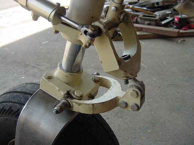 |
The nosewheel scissors uses a design idea that I learned, among innumerable other things, from John Thorp, designer of the T-18. The steering shaft is a half-inch steel rod coming down from above. When the weight is off the gear and the oleo extends fully, the upper scissor points straight downward. Its rod-end is mounted in a bushing that rotates freely in the upper stirrup, but no longer moves from side to side. The result is that regardless of what you do with the rudder pedals, the nosewheel remains centered. |